Grounding in a private home is a problem that needs to be solved first. Grounding solves the problem of protecting consumers from the damaging effects of electric current. If the insulation of wires and devices is faulty, current flows through grounding.
In this case, the protection device (RCD) is triggered and the voltage is cut off.
Grounding works fully if installed correctly and in compliance with all norms, rules and requirements of regulatory documents. When performing installation yourself, you should remember this and strictly follow these requirements.
Another function of grounding is the proper operation of electrical appliances. Some of them require a direct connection to ground, even if it is in the outlet. That’s why appliances have a special bolt (electric oven, washing machine, microwave).
When touching household appliances with wet hands, you often feel a slight tingling sensation. It is not dangerous, and you can get rid of it by connecting the ground directly to the case.
Do you need a grounding device when building your house?
The essence of grounding is that it is a device that directs electric current when electrical devices malfunction and are shorted to the housing along the path of least resistance to the ground.
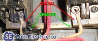
Ground bus connection for entry into the house
Therefore, all current is directed to the ground loop and does not pose a danger when a person touches dangerous devices or wires.
The mandatory use of grounding for any private residential building is determined by the rules and regulations (PUE, GOSTs, SNIP).
Another purpose of the grounding system: increases the durability and reliability of household appliances. It protects against network interference, overvoltage and sources of electromagnetic radiation.
Errors when installing memory
Typical disadvantages often encountered in practice include:
- Use as a contour of metal fences or masts. Current resistance is not taken into account and creates the risk of severe electric shock to people in the event of an accident in the system.
- Connecting the circuit directly to the housing of electrical appliances, bypassing the grounding bars in the panel.
- Installation of separate switches in the neutral conductor. If the device fails, electrical appliances may become energized. Sometimes the neutral wire contact is not strong. The consequences are the same.
- Use of products of smaller cross-section or thickness for grounding conductors. Such electrodes quickly fail under the influence of corrosion.
- Use as a grounding conductor for the working “zero”. There is an increased likelihood that the system will be energized.
- Location of horizontal grounding conductors on the surface of the earth. In the event of an accident, the affected area will increase.
- Ground connection to the heating pipe. It is impossible to say which direction the stray currents will take, since the situation in the neighboring apartment is unknown. The likelihood of electric shock to strangers increases.
Upon completion of installation work, the system is checked. Attention is drawn to the value of current dissipation resistance. To carry out this work, it is advisable to involve a specialist with the appropriate equipment.
Grounding systems. Which one is better to use?
There are six such systems, but in our reality, as a rule, two are used: TN-SC and TT. Consider TN-SC, this circuit provides that the neutral wire (N) at the substation is grounded. In this case, earth (PE) and zero (N) are supplied to a private household by one wire (PEN) and then at the consumer’s electrical panel they are divided again into two.
TN-SC grounding schemes for a private house
In the case of using such a grounding scheme, the presence of automatic circuit breakers is sufficient for protection; an RCD is not necessary. But, you should know that when the PEN wire to the household breaks, a phase voltage appears on the ground bus in the house. According to the PUE rules, PEN wire protection and grounding on poles are required after 100 or 200 meters.
Due to long-term use and wear and tear, most power lines do not meet these requirements. Therefore, it is recommended to use the TT system. In this scheme, the PE wire goes to the panel from the ground loop, and not from the substation (TN-SC scheme). In this system, the protective wire is more protected, but it is necessary to use an RCD or a circuit breaker. Without them, protection is not provided; their use is mandatory.
TT grounding diagram for a private house
PUE 7, clause 1.7.59 states that if the electrical safety conditions in the TN system cannot be ensured (i.e. the main line is in such a deplorable state that it cannot ensure the reliability of the PEN conductor), then only then is it allowed to be grounded according to the scheme TT.
Installation of accounting and security devices in the panel
Now it’s time to install all the other elements on the DIN rail. The complete list of equipment required for the panel of a private house is as follows:
1) Steel electrical panel (protection rating IP54 or higher)
2) Box/casing for AV for 3 modules
3) Three-pole circuit breaker 25A
4) Three-phase electric energy meter 380V
5) distribution block for DIN rail
6) Selective RCD from 40A, leakage current 100mA or 300mA
The electricity meter must be three-phase, for 380V networks. Usually electronic, two-tariff is chosen. When choosing a manufacturer, the main guideline is the warranty period; the one with the longest warranty should be taken. Usually a simple one is taken, without unnecessary interfaces, for example, Mercury or Energomera.
The distribution block must have a sufficient number of terminals for the required conductor cross-sections. For the option with a VDT - residual current switch, with CT grounding, you will need:
1 terminal – 16mm.kv – for re-grounding circuit PV1 or PuV (PuGV)
2 terminals of 6mm.kv - for internal conductors used for switching
The fire protection RCD is selected selective - having a delay when triggered. The leakage current can be either 100mA or 300mA.
The choice of the response threshold of the Residual Current Device depends on many factors. Almost any electrical appliance has some leakage and this is normal. If there are many such devices, the total losses can be large.
Based on this, this value is selected. If the housing is small, it is enough to set 100mA. If this is a cottage, with a lot of technology and equipment, then definitely 300mA.
For internal connections in the panel, it is most convenient to use flexible wires PuGV (also called PV-3) 1x6mm.sq.
and NShVI tips.
What is a ground loop: definition and device
A ground loop is an electrical device with low electrical resistance that allows you to quickly drain electric current into the ground. It consists of two parts connected to each other - an external and internal system. The connection of these parts is carried out in the electrical panel located at the entrance to the house.
The external system is a device that allows electric current to pass into the ground and then distribute it over an area. It usually consists of several electrodes driven (buried) into the ground and connected by welding with plates of a certain cross-section. From them, the welded tire extends into the shield, where it is connected to the inner part.
Grounding installation in a private house
What is an internal subsystem? This is the distribution of grounding wiring throughout all rooms and areas of the house to sockets and to powerful electrical installations. A common bus is formed, which is connected to the external circuit in the electrical panel.
The protective properties of grounding are very simple. If the insulation of the wires is broken, the current from the electrical network through the wires of the internal system enters the external ground loop. It flows into the ground along the electrodes of this circuit. It is known from electrical engineering that the earth has a large electrical capacity, which gives confidence in the absorption of such electrical leaks.
Installation of a box for an input circuit breaker
In order to prevent unauthorized connection, bypassing the electric meter, all switching and protective devices located before it must be closed in boxes (No. 2 in the image) and sealed.
So, during installation, we first install a special housing for the AB (circuit breaker). It differs in that it has “ears” for easy filling. In a three-phase 380V network, the box is installed on at least three modules so that the Circuit Breaker fits there.
Types of ground loops
For the grounding system to operate effectively, it must distribute the current “draining” into the ground over several electrodes that increase the dissipation area. There are two main types of grounding systems.
Ground loop - triangle
This type of circuit uses three pins, which are welded using strips into a triangle with equal sides. The length between the electrodes is selected depending on the length of the electrode penetration to two such depths. Those. for an electrode length (depth) of 2m, the side of the triangle will be 2-4m.
Ground loop - triangle
Linear
If it is impossible to make a closed figure due to the configuration of the area, a variant of several electrodes is made, they are placed in a semicircle or in a line. The gap between the driven pins should be 1-1.5 times the immersion depth of the pins. The disadvantage of this method is the large number of electrodes.
Ground loop - linear
The proposed types are the most used in the design and installation of grounding systems. It can be made in the form of any geometric figure (rectangle, circle, etc.), but you must understand that this will require an appropriate number of grounding pins. The main advantage of such systems is that if the connection between the electrodes is broken, the functions of the grounding system are preserved.
Important!
The linear circuit operates on the principle of a garland and damage to the jumper puts a certain section of it out of service.
Rules of service
After installing such a grounding system, it is imperative that it be properly maintained. Maintenance will consist of the following tasks: once a year, open the electrode cover and check the level of salt in the system. If the mixture later completely turns into an electrolyte, then you will need to add the required amount of salt to the electrolytic ground.
This is the main feature in service. If you do everything correctly, then remember that this type of grounding can last for 15 years. That is why it is recommended that you carry out inspections regularly.
Ground loop requirements
For effective operation of grounding according to the PUE, it must comply with the rules:
- Grounding pins welded into a circuit must be located at least 1 meter and no more than 10 meters from the house. The most correct distance from the foundation is 2-4 meters.
- The rods must be driven to a depth of 2-3 meters.
- The electrodes are connected using a metal strip using welding. A bus of more than 16 square millimeters is used from the shield to the ground loop. To connect wires to grounding in the shield, it can be done using bolts.
- The grounding resistance for a voltage of 380 volts should be no higher than 4 ohms, and for a voltage of 220 volts - 8 ohms.
The external part of the grounding system is buried in the ground, so certain requirements are imposed on it. It must be below the freezing point of the soil, otherwise the electrodes will be pushed out due to swelling of the earth. The electrodes must be such that they can be driven into solid ground.
Recommended types and parameters of driven electrodes:
- corner metal thickness of at least 4 mm, any size;
- a pipe with a diameter convenient for driving, with a wall thickness of at least 3 mm;
- a rod with a diameter of at least 14 mm, a smaller one bends when immersed in the ground;
- strip for connecting electrodes, at least 3 mm thick and more than 10 mm wide.
The minimum length of the electrodes is chosen to be 1.5 meters, the pins are located at a distance of 1-2 lengths of the electrode. It should be taken into account that the electrodes (their length) should be 15-20 centimeters below the soil freezing level.
Application Feature
As the freezing temperature of the soil decreases, a talik zone forms near the device. It can pose a danger to the foundations of buildings, objects and road surfaces that are nearby. The talik zone has the shape of an oval and its size on the soil surface is 3x6 meters.
During design work, it is necessary to take this fact into account and install electrolytic grounding at a certain distance from objects and buildings to which it can cause damage and harm.
We are developing a scheme
In order to organize a grounding device for a private house, it is necessary to work out a grounding circuit diagram. The most popular and most frequently used is the triangle diagram.
As a rule, 3 electrodes stand at its vertices; you can add additional ones, which are driven in a straight line between the vertices.
If it is impossible to make such a contour, the electrodes can be installed in a line, rectangle, semicircle or wave. But it should be noted that the triangular ground loop scheme is much more efficient.
Main advantages
If you decide to compare standard ground electrodes, then we can say with confidence that the electrolytic system will have the following advantages:
- Installation of the structure will be quite quick and convenient. This is due to the fact that the structure will not be large. To install such a unit, you no longer need the help of professionals.
- The mixture located inside the electrolyte will not react immediately. Thanks to this, a constant electrolytic balance will be maintained in the soil.
- The product resulting from such a reaction can be considered completely safe. It will not lead to corrosion.
- The duration of the reaction allows the use of such grounding for up to 15 years.
In most cases, such a grounding loop will be used in cases where conventional grounding cannot be installed. This is due to the fact that the cost of the kit will be quite high.
Electrolytic grounding can now be calculated using the following formula:
Where:
- C is the coefficient of electrolyte presence in the system.
- P is the resistivity of the soil where the grounding will be installed.
- L – length of the grounding device.
- D – diameter of the ground electrode.
- T – additional depth.
Ground loop materials
The electrodes for the grounding system are made from a durable metal profile or rod. If they are thick enough, their electrical resistance must satisfy the requirements. They can be driven into the ground relatively easily by hammering them. Materials used for the manufacture of the ground loop:
- Kernel. A rod with a diameter of more than 14 mm is taken. Reinforcement, as a rule, is not used for these purposes, because When hardening reinforcement, its resistivity increases.
- Pipe. Diameter more than 40 mm, wall thickness not less than 4 mm. It is recommended to make holes at the bottom of the pipe. In arid climates and weather, salt water can be poured into the pipe, this increases the electrical conductivity of the soil.
- Corner. Size 50x50, thickness at least 4 mm. The bottom of the corner is made sharp, which facilitates the process of driving it into the ground.
Reinforcement as a universal material
Steel reinforcement, which is solid metal rods, is widely used to strengthen and increase the load-bearing capacity of the main structure in buildings and production. Reinforcement is used mainly in those places of a building structure that are subject to tensile effects (bending, tension, compression). This type of rolled metal is the most important component of reinforced concrete. In accordance with GOST, steel reinforcement is made from high-strength low-alloy steel or the reinforcing steel is subjected to heat treatment and strengthening of its physical properties. Steel reinforcement consists of bars or rods of various sizes from which the desired structures, such as a mesh or frame, are made. Based on the nature of the profile, it is divided into smooth and corrugated. According to manufacturing technology, there are 2 types of reinforcement: hot-rolled rod and cold-drawn wire.
What to make metal connection from
Metal connection, i.e. The connection of electrodes driven into the ground is carried out using the following materials:
- Copper wire or bus, cross-sectional area - 10 square meters. mm and more.
- Steel tire, cross-section - 48 sq. mm.
- Aluminum wire or strip, cross-sectional area more than 16 square meters. mm.
For such purposes, a steel strip of 25-30x5 mm is preferable. The connection of such a strip to the electrodes is made using electric welding, which ensures a reliable connection. When using aluminum or copper conductors, the connection is made using a bolted connection.
Location of grounding device pins
Self-installation of grounding
A location must be selected for the ground loop. It should be located where people and your pets will least likely enter. There should be a distance of more than 1 meter from the foundation. Marks are made on the site where the pins will be located. They are arranged in the shape of an equilateral triangle.
Excavation. After applying the markings in a straight line between the pins, a trench half a meter deep is dug. The same trench for laying the busbar is dug from the ground loop to the input electrical panel.
Next, adhering to the chosen pattern, we drive in the rods to the required length. They are connected by a strip of metal by welding. Next, the busbar welded to the ground loop is laid in the trench to the electrical panel.
Entering the house. The bus connected to the house is inserted into the electrical panel. A hole is drilled in it and connected with a bolt and nut to a specific cable core. With the TN-CS scheme, the busbar inserted into the shield is connected to the busbar - the splitter.
Examination
After completing all installation and connection operations of the ground loop, it is necessary to check it by measuring its electrical resistance. The parameters of this value should not exceed the limits specified in the regulatory documents.
You can use a simple test method at home. A light bulb from 100 to 150 W is connected between phase and ground.
Checking grounding performance using a lamp
Based on the glow of the lamp, conclusions are drawn:
- if the lamp does not light up, the grounding is done incorrectly;
- the lamp burning with a dim, dim light indicates a poor-quality connection of the ground loop elements or connections during connection;
- A bright lamp indicates good grounding performance.
During such a check, if there is an RCD in the circuit, it may operate, which indicates the operating condition of the circuit.
Check with a multimeter.
Checking grounding with a multimeter
It is carried out according to the following method:
- it is necessary to apply voltage by turning on the input circuit breaker;
- On the multimeter, select the voltage measurement mode;
- We connect the ends of the multimeter between the phase and neutral wires. The device should show a value around 220 volts;
- We make a similar measurement between the phase and the ground wire. The voltage may be slightly different from the previous measurement, but its very presence indicates the presence of ground;
- if there is no voltage, then there is no grounding, or it is not working.
The inspection can be entrusted to professionals. This check is shown in the video:
Checking the ground loop by professionals
Is it possible to use fittings for grounding in an apartment?
Tell me, is it possible to use the reinforcement of a Khrushchev-type panel house as grounding? If so, would such protection be good? Second question: what can you use to ground a steel bath other than the shield? For example, to the same fittings, etc.?
Hello! If the fittings have a good connection to the ground, in principle it is possible, try measuring the voltage between the phase and your fittings. If it is close to 0, then there is land there. To understand how good the ground is, try connecting at least a 100 W incandescent lamp between the phase and the fittings. If, after connecting the lamp, the voltage at its terminals differs from that in the socket by more than 5 volts, there will be no normal protection. First of all, to prevent the bath from shocking, equalize the potentials in the room; to do this, connect all the metal elements in the room to each other, each with a separate wire to the PMC bus.
And how should a lamp burn if it is well grounded, does it dim than from a socket?
If the ground is good, then the lamp should glow brightly. But this is not entirely true. This needs to be measured with an Ohmmeter. According to the PUE, the resistance of the ground loop should be up to 4 Ohms at 380V and up to 8 Ohms at 220V, and at a facility with a 380/220V network - up to 30 Ohms. This article tells you more: https://samelectrik.ru/kak-izmerit-soprotivlenie-kontura-zazemleniya.html.
One wire to the phase and the other to the fittings shows 200-210 v, what does this mean? Could the valve be zeroed? And isn’t it dangerous to ground the fittings because they can come into contact with an iron heating riser?
How many volts between phase and zero? You've done a number of tests and all point to a bad ground. It is not clear what kind of grounding can be dangerous for the fittings and that it comes into contact with the pipeline? It is also laid in the ground.
Between phase and zero 220. Everyone says that it’s impossible to go to the fittings to the risers, that in cases where current comes through the pipes, etc. to the panel, there’s also just grounding there, where is it possible?
Why do you need grounding so much that you have been asking for permission to ground the fittings for a week now? Set the RCD at the input to 30 mA, preferably 10 (if there are no false alarms) - it will also work in a two-wire circuit when you touch the current-carrying part. The fact that there is 220 is without load, many also have a heating battery, if you connect a light bulb, it won’t even try to burn, and the multimeter shows the rated voltage.
I checked that when connected to the socket the LED lights up normally, but when connected to the fittings it lights up dimly by about half, will this be a normal grounding?
Ready-made kits
Making grounding yourself can significantly reduce costs. But there are ready-made kits that can increase the reliability of the circuit.
Ready-made kit for grounding installation
The following models are available on the market:
Elmast - the system is manufactured in Russia. Cost - 8000 rubles.
ZandZ - stainless steel electrodes. The depth of immersion in the ground is up to 10 meters. The kit will cost 23,500 (electrodes 5 meters long).
Galmar - average cost - 41,000 rubles (electrodes up to 30 m long).
There are several models on the market for Russian consumers. This gives you a lot of options to choose from. The cost ranges from 6,000 to 28,000 rubles.
Installation of a ground loop in a private house
Principle of operation
If you understand the structure of this system, then you can understand that electrolytic grounding will work based on the occurrence of chemical reactions. Grounding can work according to the following principle:
- The mixture will need to be poured into the full electrode. It will absorb moisture from the environment through a special hole.
- Now the water will react with salt and as a result, an electrolyte will be formed, which seeps into the soil. Thanks to this kind of work, the soil will become electrically conductive and not prone to freezing.
This reaction will occur regardless of the temperature present in the environment.