Connecting a single-key switch to a light bulb, sconce or chandelier would seem to be a simple task.
However, even here you can make a number of mistakes that at first glance do not seem so obvious. Let's look at the connection diagram for such a switch and step by step from A to Z we will find out how all the wires are connected in the junction box, in the switch itself and on the lamp and what can be done wrong.
Initially we have:
- place for installing a switch
The recommended height is 0.9 m from the floor level. At the same time, position it so that when the door is open, it does not interfere with its activation.
- distribution box above the switch
- lamp on the ceiling
Electrical wiring installation
We will assume that no wires have yet been laid anywhere. Therefore, first of all, lay the three-core power cable VVGng-Ls 3*1.5mm2 in the groove from the panel board to the junction box.
For further disconnection of wires inside, leave a margin of about 10-15cm. You will need it when, for some reason, you experience a short circuit or contact burnout, and you can easily bite out the burnt wires and connect everything again, without cutting or laying a new cable.
The cable cores in the panel board are connected to a separate lighting circuit breaker with a rated current of no more than 10A.
In the junction box, the cable is stripped and the conductors are labeled according to the color and how you connected them in the panel:
- L – phase
- N – zero
- Pe – grounding conductor
By the way, it is advisable to preserve all markings, including the cables themselves, and not just their cores. This will help you in the future, when connecting new lines or repairing this wiring, to quickly figure out which cable comes from where and where it goes.
You can sign with a marker directly on the walls of the box itself.
When marking cores, try to follow the colors approved by the rules.
- Blue – zero
- Yellow-green – earth
- Gray, white, brown, etc. – phase
Reworking the device
The process of converting a simple switch into a walk-through is accessible to everyone with their own hands. Its appearance is no different from its brother. It can have 1 key, 2 or more. The difference between these devices is visible only from the inside. The pass-through serves to switch circuits, so it is more correct to call it a switch. Most often at home you have to use a regular single-key main switch. In large rooms, a device with several keys is sometimes required.
Our readers recommend!
To save on electricity bills, our readers recommend the Electricity Saving Box. Monthly payments will be 30-50% less than they were before using the saver. It removes the reactive component from the network, resulting in a reduction in load and, as a consequence, current consumption. Electrical appliances consume less electricity and costs are reduced.
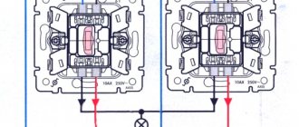
The modification consists of adding a contact: instead of 2 you need to put 3. How to connect a pass-through switch to the network? A three-core cable must be laid between a pair of devices. The phase always goes to the switch, zero - to the light fixture. Nowadays, photo relay circuits are made using KT315B transistors or Q6004LT. Our task is to make a pass-through switch from a regular marching switch with our own hands. To remake, you need to take a one-key switch and a two-key switch. It is desirable that they be produced by the same manufacturer and have the same dimensions. For a two-key switch, the leads for the wires are rearranged and 2 keys are replaced with 1. The switch, made by yourself, is ready. He can be:
- single-key, equipped with or without backlight;
- two-key with or without backlight;
- three-key;
- overhead;
- built-in;
- intermediate.
Such devices, which you can make yourself, have some disadvantages:
- by the way the buttons are located, it is impossible to determine in what position the device itself is located;
- You cannot turn the light on and off at several points at the same time.
When the light is off, it is not clear whether the switch is on. It's hard to tell by the position of the button. You cannot control the light in multiple places. For example, on both sides of the bed and at the entrance to the bedroom.
Two or three wire cable?
Next, run the second cable from the top of the junction box to the switch installation location. For a single-keyboard player it should be a two-wire VVGng-Ls 2*1.5mm2.
At the same time, many experienced electricians still recommend initially placing a three-wire wire in the groove. Although a simple light switch does not require a third core (it will remain unused), however, in the future, you can easily replace a single-key switch with a two-key or pass-through one.
There is no need to re-drill the walls or tear off the wallpaper.
It is no longer possible to connect more “complex” switches with a two-wire wire. The schemes there will be completely different.
The same applies to the bathroom. If during the repair process you install a three-core wire on a single-key switch, then later it can also be changed, and the exhaust fan can be powered from the second key.
The cable is stripped on both sides, and its cores are labeled L and L1.
- L – incoming phase
- L1 – the same phase, but already going to the lamp
Application area of pass-through switches
Installation and connection of a pass-through switch will be useful when controlling lighting systems in the following cases:
- in the presence of large corridors or walk-through rooms;
- when controlling lighting fixtures at the entrance to the room and directly near the bed;
- when installing lighting in large industrial and industrial buildings;
- if necessary, control the lighting in the next room;
- in the presence of stairs connecting several floors (in most cases in cottage premises) and so on.
Let us consider in more detail what the requirements for the installation of electrical accessories are, the basic installation rules and what is the wiring diagram for the pass-through switch.
Connection diagram
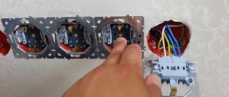
Next, the switch itself is connected. To do this, you need to carefully disassemble it without breaking anything.
Use a screwdriver or your hands to pry and unclip the key. If it doesn't come off, try pushing it from the other side.
Unscrew the two screws and remove the decorative cover.
The whole connection diagram actually consists in the fact that you need to install this same one-key switch into the phase conductor break, which will break the phase with its contacts.
Therefore, down to the light switch, only the phase is turned on, without zero.
Roughly speaking, imagine that you have a solid power cable going to the light bulb. You need to cut only the phase on this cable and insert a light switch into this gap.
The scheme is very simple and uncomplicated. The only thing is that the junction box as an intermediate link causes some confusion for many.
Connect core L to the upper contact, core L1 to the bottom.
After that, the device can be fixed in the mounting box by tightening the side spacer tabs with a screwdriver.
In the event that you have clamp terminals not at the top and bottom, but at the same level (bottom connection of wires), insert two wires L and L1 into any of them, no matter which one where.
When there are inscriptions “L” and “1”, then “L” is the incoming phase, and “1” is the outgoing wire to the light bulb.
What is important to know?
The wiring diagram and methods of connecting a device such as a circulation pump to electricity can have different designs. The choice of a specific option is determined by the characteristics of the heated object, as well as the location where the device is located. There are two ways to connect it:
- direct connection to a 220 V power supply;
- connection to an uninterruptible power supply, which in turn is connected to a 220 V or 220/380 V network (in the case of a three-phase UPS).
By choosing the first method, the consumer risks being left without heating in the event of a prolonged power outage. This option can be considered justified only if there is a high degree of reliability of power supply, reducing the likelihood of a long power outage to a minimum, and also if there is a backup source of electrical energy at the site. The second method is preferable, although it requires additional costs.
Connecting the lamp
All that remains is to lay the cable to the lamp and connect all the wires in the junction box under the ceiling. The lamp also uses three-core VVGng-Ls 3*1.5mm2.
Even if you have a lampshade or the case does not have metal parts, still pull a 3-wire cable there.
The cable cores are signed as follows:
- L1 – phase from switch
- N – zero
- Pe – earth
Connect a lamp, chandelier or single light bulb socket according to the diagram.
Wire connection diagram in the distribution box
Now we move on to connecting all the wires in the junction box. You should have three cables going there:
- power cable from switchboard
- going down on the switch
- on the lamp
First, connect the neutral conductors N and the grounding conductors Pe. They must go directly from the panel to the lamp, bypassing the switch itself.
The most convenient way to do this is with Wago clamps.
For lighting lines they are a completely acceptable option. And even those who constantly criticize them and never put them on socket groups still use them in lighting circuits.
After this, we connect the incoming phase L from the panel cable to phase L, which goes down to the switch. We connect the other phase L1 from the lamp cable to the L1 core from the single-key switch.
Check the entire diagram again. The power phase should come from the panel and go to the switch below. From there, return to the junction box and then follow to the lamp.
To connect two light bulbs or two lamps from one switch, another cable must go into the junction box, which will go to the second lamp. It is connected to the same wires as the first one.
Just instead of two-pin Vago clamps, take three-pin ones.
Close the box with a lid, place a decorative frame on the single-key player and check the functionality of the lighting.
All of the above seems to be elementary and simple. What mistakes can be made here?
How to disconnect a pass-through switch in a distribution box
To disconnect the cable and wire network, you must first install a distribution box. Next, all incoming cables can be connected using 3 main methods:
- Soldering
In this method, the 2 wires to be connected are pre-twisted, degreased with flux, tinned and soldered using rosin and tin. This method is considered the most time-consuming and if soldering is incorrect, there is a possibility that the contact between two conductors will be lost, which can damage the pass-through switch, lighting lamps, or in the worst case, cause a fire. However, if the soldering technology is followed, this method will ensure safe and durable operation of lighting circuits for decades. - Welding
Welding of wires is carried out using a step-down or welding transformer. The advantages of this method are high reliability, since 2 conductors are fused under the influence of high current, ensuring low connection resistance. - Installation of WAGO type terminal blocks
This type of connection of cable and wire products is the fastest, and the quality is in no way inferior to soldering and welding. The wires to be connected are simply inserted into the terminal block, after which the clamps snap into place and the cable is securely fastened into a special groove.
Important! When connecting wires in a junction box, it is forbidden to use ordinary twists, since over time, when electric current passes through the twist, the contact deteriorates and a short circuit may occur, followed by a fire. It is also prohibited to connect copper and aluminum wires without any gaskets made of other metals.
Connecting with the wrong cable
Strange as it may seem, many people still lay lighting lines with a two-core cable. Although the PUE and clause 7.1.36 tells us the opposite.
Moreover, they choose any cross-section of this wire, from 0.5mm2 to 1.0mm2.
In addition, for all electricians, it has long been an axiom that brands such as ShVVP or PVS are prohibited as wiring for stationary lighting. However, they can also be found in apartment renovations.
Therefore, remember once and for all - the cable for connecting lighting in apartments must be:
- three-wire
- cross section of at least 1.5mm2
- brands VVGng-Ls or NYM
Many will ask, why do we need a three-core cable if all the lamps in the apartment are plastic and there is simply nowhere to connect the ground wire?
In the PUE there is a corresponding clause in this regard 7.1.70
It turns out that even if your lamp is not equipped with contacts for the protective conductor, this is not a cancellation for clause 7.1.36. That is, the wiring to all light bulbs must be three-wire.
Some electricians recommend carefully wrapping the unused third grounding conductor near the light bulb socket around the phase and neutral. Approximately as follows.
In this case, if the insulation on the conductors is damaged, a leak will occur and the RCD will trip, protecting you from a possible fire. The same thing will happen if you accidentally damage the cable insulation without shorting a phase or zero.
That is why a three-wire circuit in lighting circuits is used to trigger differential protection when the short-circuit current is insufficient to trip the circuit breaker.
And the use of three cores is mandatory here.
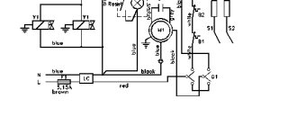
Using thermal relays with magnetic starters
The possibility of triggering the thermal relay (1) is provided in case of an emergency. The circuit contact (4) is broken, followed by disconnection of the coil and return of the core to its original state by special return springs. After disconnecting the contacts in this way, the dangerous voltage is removed in the emergency area.
Connecting a magnetic starter together with a thermal relay provides reliable protection of electrical units from possible overloads. These devices serve as an effective addition to automatic machines, the bimetallic strips of which cannot always protect during an accident. Although, the principle of operation of a thermal relay is the same as that of the thermal element of an automatic protective switch. However, the thermal relay does not automatically switch off, but only sends a set signal to perform this operation. It must be accurately and competently recognized, and put into practice in a timely manner.
A thermal relay equipped with power contacts can be directly connected to a magnetic starter without the use of conductors. However, products from different manufacturers may not match, fit or interact with each other.
Each thermal relay is equipped with two groups of contacts, independent of each other - normally closed and normally open. To break the circuit, a closed contact is used, operating through the STOP button. All working contacts are present in the circuit intended for control. They are connected directly next to the coil, but can be placed in other convenient places.
The actuation process of the thermal relay is completely invisible from the outside. Returning to the original state is carried out using a small button located on the panel. You do not need to transfer the contacts immediately, but only after the relay has cooled down, otherwise they will not be securely fixed. Before the very first use, it is recommended to press the button to avoid careless switching during transportation.
The switch disconnects zero, not phase
The second common mistake is connecting through the switch not the phase conductor, but the neutral one.
A single-key switch, as well as other types of light switches, should always break the phase. This is done for your own safety, so that when replacing a light bulb in a socket or repairing a chandelier, you will not get an electric shock.
Please note that even if you initially did everything correctly, before reaching into the contacts of the lamp after turning off the light, always check the absence of voltage with an indicator screwdriver.
The fact is that after time, the phase and zero can change places. Even without your participation. How is this possible, you ask?
Elementary. An illiterate electrician from the management company, when replacing your single-phase meter, could have mixed up the wires and connected the neutral wire to terminal “1”, and the phase wire to terminal “3”. Or accidentally swap the wires from terminals “2” and “4”.
As a result, in all distribution boxes in the apartment, phase and zero will automatically change places. And the light switch, which was originally connected correctly, will begin to break the neutral wire.
Therefore, the rule “turn it off - check that there is no voltage” is the key to your safety.
Well pump kit
Submersible pumps for meeting domestic needs are designed to work in wells Ø 75-100 mm. Models are distinguished by power, pressure, performance and type of drive (single-phase, three-phase).
The standard configuration of pumping equipment is as follows: a pump plus a power cable.
This arrangement may be sufficient if the device is intended to be used at the dacha for watering the garden.
To organize water supply at home, the devices are equipped with a control panel and additional equipment:
- automation unit;
- pressure gauge;
- pressure switch;
- hydraulic accumulator;
- check and drain valves;
- filter elements;
- deep-well pump protection unit;
- electrical voltage stabilizer.
The control package consists of a relay and a set of sensors that monitor the state of the installation and allow it to operate autonomously without human intervention.
The membrane accumulator is designed to equalize the pressure of the water supply system.
A protection sensor and voltage stabilizer support the operation of the mechanism during emergency situations, including:
- low water level in the well;
- phase failure;
- power surges;
- short circuit;
- pump overload or underload;
- engine overheating.
The switch is turned off with the up or down key
When installing the switch in the mounting box, pay attention to the position of the key when turning the light on and off.
According to the recommendations, the switch should be positioned so that when you press the key down, the light turns off, and when you press the button up, on the contrary, it turns on.
It is believed that in an emergency it is much easier to reach out with your hand and press the key down, thereby interrupting the electricity. The same applies to switches and modular circuit breakers in the panel room.
For rotary bags, electricians have their own unspoken rule, which is based on the position of its handle.
“It works - it works. It’s lying there – it’s not working!”
To be fair, it must be said that there are no clearly stated prohibitions on installing a light switch in a certain way and in no other way. Please remember that this is just a recommendation.
And everything is determined primarily by the brand and manufacturer of the product.
conclusions
A pass-through switch is a modern electrical accessory that allows you to control lighting from 2 or more places. It allows you to turn lights on or off at the beginning and end of a room, at the top and bottom of a flight of stairs, or to control the lighting in an adjacent room.
The connection diagram for the pass-through switch makes it easy to install it yourself with minimal knowledge in electrical engineering and the presence of a certain tool.
Important! When installing a pass-through switch with your own hands, be sure to check the cable and wiring products for integrity using a conventional multimeter, since there are cases when the cable may be damaged, as a result of which, even with correct switching, the circuit will not work.
Connecting an illuminated switch
Many people are also frightened by the effect when installing a backlit switch. This applies to the moment when, even in the off position, the LED light bulb on the ceiling continues to barely glow.
Someone starts to think that he made a mistake in the circuit, climbs into the junction box again and looks for what’s wrong. However, there is no error here and it is all related to the built-in LED.
Read a separate article on how to get rid of this common problem.
Sources - https://cable.ru, Kabel.RF
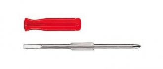
Tools
Before proceeding to connecting the switch to the network, you need to prepare a number of tools:
- curved, straight and indicator screwdrivers;
- connector;
- sharpened knife;
- pliers.