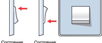
A circuit breaker is a convenient and practical replacement for fuses, which not only has higher tripping accuracy, but can also be used a large number of times. How to properly connect a machine is a question that not only novice electricians, but also every self-respecting owner of a private house or apartment should understand. And this article will not only tell you how to install an automatic or differential switch, but will also introduce readers to the variety of switching equipment and the operating principle of package switches.
Design of a standard circuit breaker
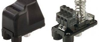
For example, we will use the BA47-29 series switch as the most popular switching device with an affordable pricing policy. Before you learn how to properly connect a circuit breaker to a single-phase network, you need to consider its design.
The BA47-29 series circuit breaker consists of the following elements:
- A copper terminal connected to a fixed power contact. Most often, the supply wire is installed exactly in this place.
- The movable contact, which makes the switching, and the copper stranded conductor, has a sufficiently large cross-section.
- Arc chamber.
- A special thin plate with a hole through which gases formed after the arc escape.
- An electromagnetic release, presented in the form of a simple coil. The stranded conductor from the moving contact is soldered to the coil.
- Plastic, fully dielectric handle.
- A bimetallic plate that acts as a thermal release. The plate is located immediately behind the reel.
- A special screw for adjusting the bimetallic plate. The screw is not installed on all models, and adjustment is made at the manufacturer.
- The lower copper terminal, from which the conductor goes directly to the consumer.
A three-phase machine has a similar design, but instead of one terminal, it uses three, isolated from each other.
What is a machine gun
- Cocking handle. Brings the device into working condition. If necessary, you can also turn off the machine yourself by moving the lever to the bottom.
- Enabling mechanism. Located inside the case.
- Contacts. They are intended to close and open a circuit.
- Clamps. Connect to a device that provides protection.
- Mechanisms. This is a temperature-triggered release plate. Having a bimetallic base. Many machine designs have a current adjustment screw.
- Arcing chamber. It may be located inside, in different poles of the machine.
Enter from above or below
A very important question that worries both many electricians and just home craftsmen: how to connect the machine, from above or from below? To answer this, you will have to refer to the regulatory documentation, namely, the Rules for the Construction of Electrical Installations.
Paragraph 3.1.6 states that the machine should be connected to the electrical network from the side of the device on which the fixed contact is located. This means that the voltage in a single-phase or three-phase network must be on the side of the switch that does not break the electrical circuit. Paragraph 3.1.6 applies to many types of switching equipment. This can be not only a single-contact, but also a two-pole or three-phase circuit breaker, as well as a differential package or RCD.
You can find out the location of this contact only by disassembling the bag, which is not very convenient every time you replace it in the apartment. But the design of all machines is almost the same, so you should find out where the fixed contact is located on only one switch. And it is located on top, so the connection of a single-pole or two-pole circuit breaker must also be done from above.
If you happen to have a packet from an unknown manufacturer in your hands, then just look at its body, or more precisely, the front panel. In this place, most often all the necessary information is placed on the machine, such as the model, accuracy class, and connection diagram of the circuit breaker with the exact location of the moving and fixed contacts.
Conclusion: the connection of the circuit breaker to the electrical network must be done from above. This is what the regulations say, which help avoid unnecessary confusion. But if you look from the technical side: is the difference in connecting the power cable significant? Answer: no, it does not matter at all from which side the operating voltage is supplied to the package. The device will work properly both with connections from above and from below.
Industrial or homemade shield?
Nowadays different shields are sold. All kinds of shapes and sizes. They have either a primed metal, painted base or a plastic base. There are also brushes with internal factory filling. There are designs available for individual order.
But, if the shield installer has certain skills, then it is better to install the internal parts yourself, at your own discretion. The more experience, the more competently the installation of the structure in a certain volume of the electrical panel will be completed.
The sequence of correct connection of the machine
Before you learn how to install the machine correctly, you need to stock up on the most necessary tools. If in the future electrical installation turns into the main type of income, then the following list of tools will not be enough.
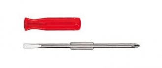
- Phillips and flat head screwdriver. Preferably dielectric.
- Indicator screwdriver.
- Monter's knife.
- Screwdriver.
Professional craftsmen also have crimping pliers in their bins, and instead of a fitter's knife, they most often use a special knife for stripping insulation. This is not only more convenient, but also allows you to get the job done faster.
Step #1: DIN Rail Mounting
Do-it-yourself installation of a DIN rail in a panel takes 10-15 minutes. The main condition for fast work is the presence of a good screwdriver, preferably with an autonomous battery.
There are three main types of DIN rails:
- Ω-type. Products of this form are considered the most common, and any circuit diagram for connecting machines in a panel implies the presence of such a product.
- C-type. The ends of the product are bent inward.
- G-type. This rail is similar to the C-shape, but with only one shorter side.
The sequence of installing a DIN rail in an electrical panel:
- Mark the location of the DIN rail in the panel.
- Place the DIN rails on the metal surface and secure them on one side using tex, a special self-tapping screw.
- Align the rail using a building level and secure it on the other side.
If necessary, the DIN rail can be cut to any length, but this product is mainly sold in 2-meter lengths.
Step No. 2: installing the machine on a DIN rail
The simplest procedure in the entire topic “How to connect a machine in a panel.” On each circuit breaker, on one side (usually the bottom) there is a special plastic latch. It must be removed, installed on the DIN rail and pressed until it clicks. After this, the circuit breaker will be securely fixed and you can proceed to connecting it.
Step No. 3: connecting the machine to the network
To find out how to correctly connect the machine in the electrical panel, you must first read the paragraph, which discusses in detail the question of whether the package should be connected from below or from above. As the regulatory documents say, voltage must be applied to the fixed contact of the switching device, and most often this contact is located on top.
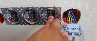
Before connecting a single-pole or double-pole circuit breaker to the network, it is necessary to remove the insulation from the wire, crimp it together with the tip and make sure, using an indicator screwdriver, that there is no voltage coming to the packet.
After this, insert the securely pressed tip into the standard connection point of the machine and clamp the connection point using a bolt specially provided by the manufacturers. Check the quality of the connection by moving the wire without applying unnecessary force. If the installation is done correctly, then the machine can be turned on and checked whether everything is working in the apartment.
Panel, counter, machines and socket - Community "Garage Affairs" on DRIVE2
Since there was no light at all in the garage, initially it was necessary to install a meter and run the wiring to it. As always, my luck at the “MIRACLE of the Masters” was in action.
An electrician from a cooperative, a rather strange man, considering that he lives in a cooperative, on the second floor of his garage. Anyway.
I gave him a machine meter and a socket with a panel with the agreement that he would arrange all the equipment into a panel, and the next day everything would be ready in my garage (Wednesday). I asked for 1000 rubles.
Important
We agreed and then off we went, either busy, sick, or some other crap! Due to being busy at work, I couldn’t go and give him a kick for a week. And so on Friday evening I went to see this ghoul, chased this asshole all over the garage, saying that the horse lay down (where did he find it in the garages?!), after which he took everything he bought and went home.
Early in the morning I sat down to assemble the shield myself, although I was undertaking to do it for the first time, I was completely confident that I would do it perfectly and it seems that it turned out that way)
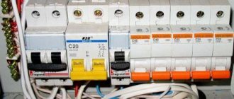
What we have: 1. Double circuit breaker for 25A (used as a switch), installed before the meter.2. Two single 25A circuit breakers, one for sockets in the garage, the other for an socket in the panel.3. One single 16A circuit breaker for lighting in the garage.4. Actually the shield itself (for some reason I visually liked the metal one).5.
Mercury meter 201.5.6. Two zero buses, one isolated, is used as a general phase distribution and the second, respectively, for its intended purpose for ZERO.7. 1 meter of copper cable with section 4.8. 7 meters of AVVG aluminum cable with a cross-section of 6 (the wiring to the garage is very old and made of aluminum).9. Corrugation (got a bunch for free).10.
Fasteners for corrugated walls.
11. Self-tapping screws with a dowel for fastening.
And now about the main thing!) I covered a piece of the metal plate on which I actually installed the elements with a film under polished aluminum) because there was nothing better to do) and then away we went.
Layout
We twist, twirl, bend the wires and do everything according to Feng Shui.
An hour and a half later, all the elements were installed as desired and everything was very neat!
On Saturday afternoon I went to the cooperative and kicked the chairman to force that asshole to install the assembled panel on the wall and connect it to the general network. In my understanding, installing a meter means twisting the wires with the street ones and putting a seal.
Common mistakes when connecting the machine to the network
Unfortunately, even experienced electricians with many years of experience behind them make minor mistakes at first glance, which can later lead to very big problems. To avoid such errors when connecting the input machine, you need to familiarize yourself with them in advance. Prevent a problem before it occurs.
Wire clamp with insulation
A very popular mistake that is made mainly due to inattention. The main difficulty is that a visual inspection may not show any results: all the machines in the electrical panel are intact, the wires are not damaged, and there is still no light in the apartment.
And the problem is the incorrect connection of the power cable, or rather, too small a section of the removed insulation. The technician removes a small piece of insulation from the wire, places it in a fixed contact and tightens the bolt. The standard connection of the machines is in the panel and everything is done according to the rules. But only the contact could get not to the conductive core itself, but to the insulation. Result: poor contact, which will lead either to a burnt-out machine or to a lack of light in the apartment. It may take a long time to determine the problem and reconnect the cable to the packager.
Therefore, in order to avoid such consequences, the connection of a single-pole or two-pole machine must be made with a high-quality stripped wire. And it’s okay if the cleaned core peeks out a little from the insertion point.
Connecting several wires of different sections to the machine
Before installing circuit breakers, you need to know how to do it correctly. And often in apartment panels you can see several wires that are installed in one regular place for connection. And it’s good if it’s 2 wires, but many craftsmen try to connect 3 or more wires of different sections to the machine. After which the life of the circuit breaker is reduced several times.
If the wires to the machine have different cross-sections, then when the contact is tightened, the one with the larger cross-section will be well secured. A cable with a smaller diameter will “walk” freely in the package’s seat. The result will be poor contact, which will soon lead to complete burnout of the connection point of the machine.
Therefore, it is best to connect the machines to each other with a single piece of wire, stripped only in places of direct contact with the circuit breaker. This piece of wire is also called a comb bus, which you can make yourself.
Connecting several machines to a meter or to each other can also be done using special crimp terminals NSHVI-2. These are consumable products into which 2 wires can be pulled at once. The only downside to this installation option is the need to purchase special crimping pliers.
Incorrect formation of core ends
How to connect circuit breakers in a panel is already known and the main errors have been discussed, but even such a minor error as incorrect formation of the end of the conductor can lead to the need to replace the switch.
The sequence of connecting cables to machines is standard: strip the core to the required length, guide the wire into the seat and tighten the lock, which is most often made for a Phillips screwdriver. They try to make the end of the conductor straight. But in order to improve contact at the junction of the wire and the copper plate of the machine, a U-shaped bend must be made at the end of the cable.
This is the most reliable advice on the question of how to properly connect machines to the input power supply or apartment wiring. The U-shaped bend allows you to increase the area of contact between the wire and the copper plate of the bag, and, accordingly, improve the quality of contact. The rest of the work will be done by the ribbed surface of the slots for connecting the machines.
Connecting a stranded wire to a machine without special ends
How to connect a circuit breaker, single-phase or two-phase, using a stranded cable? Answer: only using special crimp lugs such as NShV or NShVI.
Many electricians do not bother themselves with high matters and make this connection in two standard ways:
- Tin the end of the copper wire.
- Without using any contact materials at all, simply squeezing the wire with pliers.
Both the first and second methods are incorrect, and will soon only lead to the replacement of the machine. And if everything is clear with the second point, then cable soldering, on the contrary, is encouraged by all technical and regulatory documentation. Unfortunately, not always. Even a high-quality tinned wire under voltage gradually begins to “drain”, and in order to prevent contact deterioration, it should be constantly checked and tightened. Therefore, soldering is not practical in this case.
It is best to purchase special crimping pliers and tips NShV or NShVI. All that remains is to strip the input cable, put a tip on it and crimp it using pliers. After this, the carefully crimped stranded core can be secured in the machine and there is no need to check the quality of the connection every few months.
With press jaws, installing automatic machines will become a quick, and most importantly, high-quality procedure. This tool is especially useful when the electrician profession is a constant source of income.
Required Tools
Stripper for removing insulation
To reliably make a connection in the panel, you need to purchase special tools in advance. They must be professional and have insulated handles. Required tools include:
- Hammer.
- Bulgarian.
- Screwdrivers, including an indicator screwdriver for checking the absence of voltage on the wires.
- Knife.
- Device for stripping insulation.
- Pliers.
- Wire cutters.
- Portable lamp.
After preparing the tool, you can begin installation.
How to properly connect SIP to a machine
SIP is a self-supporting insulated wire that is used almost everywhere to introduce electricity into the house. Therefore, the question of how to connect a SIP to a single-pole circuit breaker is very relevant.
Firstly, the SIP is made of aluminum, and the contact plate of the circuit breaker is made of copper. The correct connection of copper and aluminum requires the use of a special crimp sleeve, and in the case of subsequent connection to the machine, a sleeved tip, at the point of contact of which there is a special copper coating. It is impossible to connect a SIP to a machine without such a tip, since aluminum tends to oxidize, causing the quality of the contact to be lost. And poor contact is the first cause of fire.
The sequence of connecting the SIP to the machine:
- Strip the cable.
- Place a sleeved tip on the open core. It is important to put it on tightly and so that the insulation begins immediately behind the sleeve.
- Using a hydraulic press, compress the sleeve in two places.
- Place a heat-shrink tube over the open part of the sleeve and heat it with a hair dryer.
- Insert the tip into the machine and tighten the contact properly.
This installation method is the same for both single-phase and three-phase machines; you just need more tips.
Location of the electrical panel in the room
It is important to decide on the installation location of the shield. Its location requires constant access; the switchboard door must not be blocked by foreign objects.
In most cases, the shield is mounted near the entrance to the house, or already inside, but immediately in the corridor of the house or apartment. This simplifies the installation of the cable supplying voltage to the room.
- The height of the shield is determined at the eye level of the residents of the home. This arrangement is necessary for the convenience of taking meter readings when paying for electricity.
- Previously, in not-so-distant times, meters with automatic machines were installed on a wooden plank on the wall.
- Although their location was usually under the ceiling, it is undesirable to do so. In the shield, the entire structure will be in a safer position.
Modern electrical panels have high protection classes, a good solid base, and a lock with a key. What is an obstacle for small household members to enter there.
In a private house, when placing the panel, the location of the high-voltage line from where the cable will be supplied to the room is taken into account.
Which is correct: machine before or after the counter
To answer this question, you should also refer to the PUE, namely to paragraph 1.5.36, which states that for the safe installation and replacement of meters in networks up to 380 V, a circuit breaker must be installed in front of them (at a distance of no more than 10 m) . And this same machine in front of the meter acts as a switching device to disconnect the entire apartment or house, and its nominal values must be appropriate.
The number of machines after the meter is determined directly by the owner of the apartment or house, or by the design organization performing the installation of electrical wiring. There are such electrical panels, the number of devices in which reaches 40-50 pieces, and this is without RCDs and differential circuit breakers. When installing an introductory machine before the meter, the same one can be installed after it. This will not affect the operation of the metering device in any way.
Important! Only representatives of energy supervision authorities can connect the electric meter to the network. Therefore, before connecting an apartment, you should find such an organization in your city and formally call a specialist.
How to choose a two-terminal network
To choose a good protective device, you should focus on the cross-sectional area of the connection wire. To do this you will need to calculate the value.
First, you should calculate the power and current of the equipment on the power line from the machine. For the current in the circuit, the formula I=P/220 is used, where 220 is the rated voltage, I is the current (A), P is the power (W).
Next, select the wire type based on the table.
| Current strength, A | Network power, W | Copper wire cross section | Aluminum wire cross section |
| 1 | 0,2 | 1 | 2,5 |
| 2 | 0,4 | 1 | 2,5 |
| 3 | 0,7 | 1 | 2,5 |
| 4 | 0,9 | 1 | 2,5 |
| 5 | 1,1 | 1 | 2,5 |
| 6 | 1,3 | 1 | 2,5 |
| 8 | 1,7 | 1 | 2,5 |
| 10 | 2,2 | 1,5 | 2,5 |
| 16 | 3,5 | 1,5 | 4 |
| 20 | 4,4 | 2,5 | 6 |
Based on the data obtained, you can select a machine taking into account thermal inertia during heating.
The current in the wires must be greater than the current of the difavtomat, and the latter must be greater than the current load.
How to install an RCD: before or after the machine
The residual current device is a very useful switching device that requires correct installation, otherwise its operation may be unstable. If the installation is carried out incorrectly, then at the first short circuit in the apartment you will need to replace the RCD, which is an order of magnitude higher in cost than any circuit breaker.
There is no particular difference whether the RCD will be located before or after the machine. But the issue can be considered from a practical perspective. Any residual current device does not have protection against short circuit currents, and if you install it without a circuit breaker, the consequences can be very different, including damage to the device.
Therefore, it is best to install an RCD immediately after the introductory machine, but before the packetizer, the line from which will go directly to the consumer. This will provide reliable protection of the circuit from short circuits, and users from the unwanted action of operating potential when a phase wire gets into contact with the housing of a household appliance.
Marking
Particular attention should be paid to the markings of machines.
There are special markings on the body of the machines:
- Rated current of the device (in amperes).
- Overload current group (operation current range).
- Maximum operating current or short circuit current (in amperes).
- Current limiting class (the higher the class, the higher the response speed during a short circuit).
- Graphic designation or schematic diagram of the device.
- Device series.
- The rated voltage at which the machine must be used.
How to properly connect a differential machine
Of all types of switching devices, a differential automatic machine is considered the most practical, but at the same time expensive. It combines the functions of a circuit breaker and a residual current device. Such a device is not installed like a regular package, but requires a slightly different approach.
The differential machine is connected as follows:
- The neutral wire is installed in the upper clamping contact.
- A phase wire is installed in the right clamping contact.
It should be immediately clarified that the contact locations can be changed, but the manufacturer marks the connection sockets with the appropriate letters. And under the operating or non-working position switch there should be a special button to check the functionality of the device.
The neutral wire that passes through the differential circuit breaker cannot be connected to other circuit breakers. With this installation, the device will constantly turn off, since the currents flowing through the conductor are completely different.
There are schemes in which a differential machine is connected to a group of packagers, while in other schemes such devices are used exclusively for one consumer. When designing wiring, it is better to choose the second option, in which, when the device is triggered, only one consumer will be de-energized, and not a whole group of machines.
Preparation of all necessary materials and tools
In addition to the protection devices themselves, you will need:
- DIN rail for mounting machines;
- wire sections for internal connections;
- side cutters;
- screwdriver;
- pliers;
- knife.
Important! If stranded wire is used, crimp lugs corresponding to its diameter are required. The wires used for internal connections must have a cross-section no smaller than those extending into the line.
You may be interested in this Digital electronic electricity meter
DIN rail
Installation of circuit breakers and other protective devices is carried out on a pre-fixed DIN rail, since the fastening for all devices is standard. Devices can only vary in width depending on the number of switched phases and functionality.
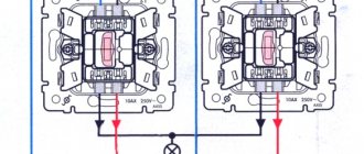
Connecting two-pole and three-pole circuit breakers
The principle of connecting two-pole and three-pole circuit breakers is exactly the same as in the case of a single-phase packet switch. And if the question arises of how to connect a three-phase machine, then you should perform all the operations that were carried out with a device designed for a single-phase network.
In the same way, strip the wires, crimp them using lugs and a press, and install each wire on the corresponding fixed terminal, and then clamp it with a screw clamp. If a three-pole circuit breaker is installed in a production facility where further connection of asynchronous or synchronous motors is planned, then after installation the phase rotation should be checked using a special device - a phase indicator. If the phases are reversed, the motor will begin to rotate in the opposite direction.
If you do not know how to connect a two-pole machine, then the principle of connecting it is the same as when installing an RCD. Standard places are provided for the connected phase and neutral wires.
It should be immediately clarified that the price for installing single-pole, two-pole and three-phase circuit breakers in Moscow varies. Therefore, it is necessary to take into account the types of switching equipment that will be installed in the panel in the future.
Advantages of application over single-pole circuit breakers
Let's consider a situation where someone confused the phase with zero. Then, when the single-pole circuit breaker is turned off, the zero line is disconnected, and the phase remains in the circuit. A person, thinking that he has protected himself by turning off the machine, starts working and receives an electric shock. To prevent this from happening, after disconnecting the single-pole circuit breaker, you need to check the absence of voltage in the circuit with an indicator. But it is still safer to use a two-pole circuit breaker, which will completely de-energize the circuit.
In the case when the RCD has tripped, it is necessary to find a fault in the circuit. First of all, turn off all electrical appliances from the sockets. If this does not produce results, the branches of the circuit are switched off sequentially, but both zero and phase must be disconnected. A single-pole circuit breaker does not provide this opportunity. You will have to remove the zero on the bus, which is problematic, since it requires dialing to find the right wire. A two-pole machine copes with this task perfectly.
Thus, the advantages:
- Safety - the electrical circuit is completely broken.
- Ease of troubleshooting.
Summing up
Key technical points to remember from this article:
- The supply wire is connected to the fixed contact of the circuit breaker. On almost every machine such a contact is located on the top.
- Only the phase passes through a single-pole circuit breaker, phase and zero pass through a two-pole circuit breaker, and 3 working phases pass through a three-phase circuit breaker. In the latter case, it is also necessary to use a phase indicator to determine the correct phase rotation.
- Phase and zero must pass through the RCD and differential circuit breaker.
- To connect wires to the circuit breaker, use special crimping lugs and press pliers. Especially when installing multi-wire cable.
- Before connecting the cable, it is necessary to remove sufficient length of insulation from the core. Otherwise, insulation will be the first cause of poor contact.
- The main circuit breaker is mounted before the electric meter in order to ensure the ability to quickly replace the electricity meter in the event of its failure.
Before any electrical installation, you should check the regulatory or technical documentation. Only then will all work with electrical devices and consumables be considered correct, and most importantly, legal.
Installation and connection
Accepted colors of phase, neutral and ground wire
Before starting work, it is necessary to de-energize the room. Using a tester, it is checked whether voltage remains on the conductors. Using the probes of a screwdriver, you need to touch each core one by one. If the light does not light up, you can start working. It is prohibited to work with electricity turned on. It is also important to prepare tools in advance and provide the master with an autonomous light source.
When connecting wires in a panel, it is important to remember that the colors of the wires indicate their purpose. The core can be completely painted in one color or another or have a color mark at the entrance to the device, that is, at the ends of the conductor. The following scale is used:
- Phase – gray, black.
- Zero is blue.
- Grounding – yellow-green.
The wire for installing the electrical panel must be laid in such a way that there are no sagging or unnecessary bends. To do this, the length of each segment is determined in advance with a small allowance of 2-3 cm.
All connections to the machine are made using jumpers. Single-wire rigid wire can be used for this purpose. If possible, it is better not to use jumpers, but to do everything through the connecting core. Thanks to it, the contact will be reliable and the appearance will be aesthetic.
It is not recommended to connect more than two wires to one terminal. If this cannot be avoided, the cables must have the same cross-section.
Purpose of boxes for machines
Plastic and metal boxes perform the same function as distribution boards - they organize the operation of electrical equipment and serve for the electrical installation of protective devices. In the specialized literature you can find other names: box, box, shield, panel.
The main “filling” for filling the box is made up of electric machines, however, other protective devices - RCDs and difautomatic devices - can be located next to them.
There are no products for sale with pre-installed equipment. Low-voltage boxes are sold empty, and automatic protection devices are selected taking into account the characteristics of the network and installed according to the selected scheme
Large boxes contain indicators, switches, timers, differential relays. But to equip the network of a private house or one apartment, installation of additional equipment is not necessary.
If, in addition to protective equipment, an electricity meter is installed inside the box, then the panel goes from the distribution category to the metering and distribution category
Boxes are installed in apartments, on floor areas, as well as on the street, if it is necessary to connect a private home to the power supply line. They are varied in design, assembly and functions.
Selecting a machine depending on the load power
For apartments and houses with new electrical wiring, the choice of machine is made based on the calculated load current.
A three-phase type device can be calculated by the rated load current or by the response speed in conditions of exceeding the current value. For calculations, you need to add up the power of all consumers and calculate the current passing through the line. Work is performed according to the formula:
I=P/U, where:
- P is the total power of all household appliances;
- U is the network voltage.
For example, the power is 7.2 kW, calculated using the formula 7200/220 = 32.72 A. The table shows ratings of 16, 20, 32, 25 and 40 A. The value is 32.72 A, taking into account the operation of the device at a value of 1 ,13 times more than the nominal value, multiply: 32x1.13=36.1 A. The table shows that it is better to install a 40 A model.
Drawing up an electrical panel diagram
An important step in installing an electrical panel is creating its diagram. There are several explanations for this. Let's say, if you plan to repair or modernize the wiring in your apartment in the future, using the diagram you can quickly establish what each machine and part in the panel is responsible for. You will also need the diagram when accepting work as an electrician. In addition, connecting wires with such a diagram on hand is much easier. You can either draw it manually or in specialized programs, and then print it.
The electrical circuit is created in several stages. The first step is to find out what kind of electrical system is in the house, then divide all points of electricity consumption into several categories. After this, based on the existing data, a shield diagram is created
It is extremely important that the diagram used symbols, which are described in detail in GOST 21.614 “Conventional graphic images of electrical equipment and wiring in the original”
So, as mentioned above, all work begins with determining the power supply and grounding system in the apartment, since the connection of the panel will depend on this. You can find out by looking at the sign on the floor or by going to the housing office. Often, three systems TN-C, TN-S, TN-C-S are installed in residential buildings.
It is worth immediately noting that the first system was created according to old GOST standards and was used in houses that were built before 1998. The TN-C system is represented by two-core copper or aluminum wiring. A three-phase cable (L) with one conductor PEN, in which ground and neutral were combined, went to the floor distribution board. The last two systems are used in modern homes. A three-core copper wire is laid in the apartment, and a cable with three phases (L), neutral (N) and PE ground (S) is connected to the switchboard.
Characteristics of the VA47-33 and VA47-35 models
Models of the BA47 series input machine have a high input voltage. The permissible relay overload level is 40 A. However, drive devices should only be connected with single adapters. Resistors for such modifications are also installed of a low-resistance type. On expanders, the resistance parameter is 30 Ohms.
Thanks to this equipment, problems with frequency failures are not a problem for machines in this series. To protect the device, a modulator with three capacitors is installed. The transceiver of the VA47-33 model is located in the upper part of the structure. The regulator of the same machine is made in a two-channel version, and it is connected to the contacts through an adapter. The varicap installed in the device is responsible for receiving a signal with a maximum input voltage of 300 V.
Functions of three-phase machines
A three-phase switch simultaneously serves several single-phase zones of the circuit.
Before choosing an automatic switch, you should understand its functionality. Users are often mistaken into thinking that the device protects household appliances. The machine does not respond to its electrical indicators, only triggering in the event of a short circuit or overload. The three-phase functions include:
- simultaneous maintenance of several single-phase circuit zones;
- preventing the formation of overcurrents on the line;
- joint work with AC rectifiers;
- protection of high-power equipment;
- increased power due to the installation of a special converter;
- fast response in short circuit mode on a line with a large number of consumers;
- the ability to turn off manually using a switch or switch;
- Compatible with optional safety terminals.
Without a automatic device, the risk of cable fire increases.
Methods for selecting a difavtomat
Rating of the difavtomat and its time-current characteristics
For example, consider a kitchen where a large amount of equipment is connected. First, you need to set the total power rating for a room with a refrigerator (500 W), microwave (1000 W), kettle (1500 W) and hood (100 W). The total power indicator is 3.1 kW. Based on it, various methods are used to select a 3-phase machine.
Table method
Based on the device table, a single-phase or three-phase device is selected based on the connection power. But the value in the calculations may not coincide with the tabular data. For a 3.1 kW network section, you will need a 16 A model - the closest value is 3.5 kW.
Graphical method
The selection technology is no different from the tabular one - you will need to find a schedule on the Internet. In the figure, the switches with their current load are shown horizontally, and the power consumption in one section of the circuit is shown vertically.
To establish the power of the device, you will need to draw a line horizontally to the point with the rated current. A total network load of 3.1 kW corresponds to a 16 A switch.