Home » Schemes » Light switch connection diagram with indication
The LED indication, which is located on the switch, allows you to find it in the dark at night. If you have already made repairs and installed a regular switch, then there is nothing to worry about. A light switch wiring diagram with an indication will help you redo everything.
If you want to convert a regular switch, then you will need to read our instructions. For a lamp that has incandescent lamps, it will be possible to use an LED circuit. If you have an LED chandelier installed, then you can use a neon bulb circuit. Now you should learn simple light switch wiring diagrams. If you are interested, then you can read about the electrical wiring diagram in the kitchen.
Connection rules
Regardless of the type, installing an illuminated switch is the same. The differences are only in a couple of nuances.
Installation of a single switch
The easiest way is to connect a single-key (single) backlit switch. First of all, you need to turn off the power and remove the old switch.
For this:
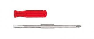
Use a flathead screwdriver to remove the key. Carefully remove the decorative trim. Unscrew the screws connecting the device to the socket box. Pull it out. Loosen the fastenings, disconnect the wires. After completing the manipulations, the inside of the dismantled switch remains on your hands
They are thrown away or used as spare parts
At the end of the manipulations, the inside of the dismantled switch remains on your hands. They are thrown away or used as spare parts.
To install a new light switch with indicator/backlight, you must repeat the steps listed above, only in reverse order:
- Insert the “internals” into the socket box, not forgetting to attach the wires to the switch contacts.
- Screw in the bolts.
- Install a decorative frame.
- Insert a key.
- Turn on the electricity to check the correct installation and connection. If the work is done correctly, the diode in the backlight will light up.
Installation and connection of switches with several keys
Connecting a double or triple backlit switch is done in much the same way. To install a design with two keys, you will need a screwdriver, side cutters, tips and an indicator with which to determine the phase.
The work is carried out like this:
As in the previous case, first of all it is necessary to turn off the power to the apartment/house. Next, the dismantling of the old device begins. Remove the keys and unscrew the screws. There will be three wires left in the socket box. One is incoming power, two more are power going to the lighting fixture. Now, using an indicator screwdriver, you need to find the phase wire, mark it or simply remember it
You need to act extremely carefully, because this stage requires the presence of voltage in the network. Disconnect the network. Strip the wires of insulation. Get a new device. It has three contact groups and a pair of wires coming from the backlight. Using a measuring device, determine the “Off” position.
Typically, the wiring coming from the LED has special contact plates for screws. The screw must be unscrewed, placed against the plate and screwed back. Repeat the action for the remaining contacts. Attach the phase wire to a plate located separately from the rest with a screw. Connect the wire going to the chandelier to the contact and secure it. Secure the last wire under the contact on which there are no plates. Check that the connection is correct. Insert the inner part of the switch into the installation box. Secure the screws. Reinstall the keys.
Upon completion of installation, connect the electricity and check the functionality of the device.
If it is necessary to control the light source from different places, a pass-through/changeover switch should be installed. Its main difference from classical models is the presence of a moving contact. If you press the on/off key, it will transfer from one contact to another, starting the operation of the second circuit.
Connecting a pass-through switch with backlight
The connection diagram for the pass-through switch is extremely simple. Two separate devices are installed on both sides of the circuit.
To do this, you will need to lay a three-core cable to one and to the other. When the first switch is turned on, the circuit will close and the lamp will light. When the second one is turned on, the light will turn off.
Installation and connection of switching devices with backlight
The indication chain has almost no effect on the operation of the switch, and for its operation it does not matter which side the phase wire comes from. Therefore, for standard key devices, the presence of backlight does not change anything. The device is also mounted in a phase wire break. The supply core is also connected to it, and conductors depart according to the number of loads. But there are several points.
Installation of switches with one key
Installation and connection of single-key devices has no special features. But we must take into account that the indicator can be located either at the top of the device’s panel or at the bottom (sometimes in the middle). Therefore, there is no point in relying on the position of the lamp to determine the on position of the keys.
Switches with an upper and lower location of the light-emitting element.
Features of connecting a device with two keys
When connecting a two-button backlit lighting switch, you must keep in mind that in most cases only one pair of contacts is equipped with an indication. Therefore, when one of the keys is turned on, the light-emitting element will go out and the device will remain without an indication. This does not matter if the device switches two lighting systems in one room. But it can be important if the switch controls the light in two different rooms (toilet and bathroom in a separate bathroom).
Illumination circuit of a two-key device.
Connecting a pass-through switch with an indication circuit
For a pass-through device, the described principle of deshunting the circuit is of little use. If the lighting circuit is broken, the contacts of one switch may be closed. And if the backlight is installed on only one pair of contacts (like a two-key switch), then when the light is turned off this circuit will be bypassed.
Diagram of operation of pass-through switches with indication.
To eliminate this drawback, it is necessary to install illuminating elements on each pair of contacts and use two light emitters. This requires additional space inside the device and design refinements in the design of the front panel. Therefore, for marching switches, parallel circuits for connecting radiating elements are used.
Operation of pass-through switches with indication of the on position.
In the first diagram, additional elements are connected in parallel to the fixed contacts. In this case, when the circuit is broken and the lighting is off, both indicators will light up. With the main circuit assembled, both bulbs will be unpowered.
Operation of pass-through switches with indication of load activation.
Another option is a power-on indication. In this case, the indicator lights light up when the lamp is turned on. The disadvantages of such a connection are:
- the need to lay a third wire between the marching switches;
- the need to lay the neutral wire N to the switches.
And the practical usefulness of indicating the on state of the lamps is questionable. These indicators will light even if the lamp is not installed in the lamp or the cable is forgotten.
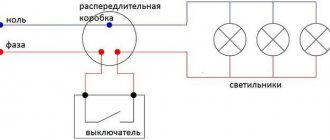
Let's look at the visual connection of the wires.
Connection
Having understood this device a little and selected a suitable model, you can begin connecting the backlit switch. We offer you to consider step-by-step instructions with which you can easily replace the device yourself:
- Before starting work, be sure to turn off the electricity at the distribution panel.
- Then you need to remove the old switch. First, the keys are removed, then you should remove the frame and take out the inner part by unscrewing the clamping screws in advance.
- Loosen the contacts and release the device.
- On the back of each switch there should be a connection diagram for this device, according to which the wires need to be connected to the new switch.
- Let's start installing the new switch. This is done in reverse order.
- Now you can turn on the switch and check the functionality of the new device and its backlight.
That's all. The main thing in this work is to take your time, and everything will definitely work out.
Turning off the switch backlight
The device allows you to temporarily or permanently turn off the firefly. It's easy to do:
- As in other cases, you must first turn off the power.
- Using a flathead screwdriver, pry out and then remove the keys.
- Remove the decorative frame.
- Unscrew the bolts.
- Remove the internal filling from the socket/installation box.
- Using an indicator screwdriver, check for voltage on the wires.
- Disconnect the wires from the contacts.
- Find the latch in the switch design that holds the two parts together. Separate them.
- Find the resistor and LED.
- Take wire cutters and cut the wires directed towards the backlight. An alternative option is to desolder the LED.
- Reassemble the switch by repeating the above steps in reverse order.
Now the indicator will not work.
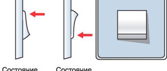
Wiring: open or hidden option
Despite the fact that installing a switch may seem like a very simple matter, there are a large number of nuances that a novice electrician must know.
First you need to decide on the type of wiring.
Open wiring is still used in everyday life. It is especially loved by designers who create interiors in retro or loft style.
Electrical wiring is an essential element present in every home.
There are two types of it:
- Open. The wires are laid on top of the wall. They can be secured with decorative rollers or covered with plastic cable ducts.
- Hidden. The wire is laid inside the wall. To do this, channels are cut into its surface into which the cable is laid. After installation, the grooves are sealed with mortar.
Each type of wiring uses a different type of switch. For an open system, choose overhead models that are placed directly on the wall. They are easily recognizable because they are very visible on the surface.
This type of switch was the first to appear and has changed little over the past decades. For closed wiring, internal or built-in models are used.
They are installed in a recess that is previously prepared in the wall. The dimensions of the hole are selected depending on the dimensions of the switch. It is attached inside the recess using special spacer legs.
There is another type of built-in devices - with mounting plates. This option is more convenient to install. After installation, the internal switches practically do not protrude above the wall plane.
Other causes of flickering
The above methods for eliminating the flickering of lamps with LED lamps are related to the switch. But there are exceptions when the light flickers and the switch is compliant.
In conclusion, it should be noted that if you postpone the search for a solution to the cause of the flickering light bulb, the energy-saving device will soon fail.
LED lamps are designed in such a way that each blink means the device is turned on. The service life of the lamps is tied to the number of switches on/off: the more often it flickers, the faster it will burn out. While repairing the lighting fixture, you can replace the LED with an incandescent lamp or temporarily install a regular switch.
Source
Various connection diagrams for backlighting in devices
As already indicated, switches can use LED or neon lamps. Their connection diagrams are also different. These points must be taken into account when purchasing ready-made devices in stores and when making them yourself. These schemes do not contain any special difficulties. For a person even remotely familiar with electrical engineering, they will be simple and understandable.
However, some nuances need to be known and taken into account, because the performance of the device may depend on them. This is especially true for the power and rating of the resistors used. The nominal resistance is calculated using the formula:
R= (Uc—Un)I{\displaystyle \Delta ABC}
- where (Uc-Un) is the difference between the mains voltage and the value of the voltage drop when the light bulb lights up,
- I is the current strength in the light bulb.
If there is no data on the LED or neon lamp, then you can take into account the average indicators: the voltage drop across the LED is 2 V, the minimum glow current is 2 mA, for a neon lamp it is 70 V and 0.1 mA, respectively.
However, only an experienced electronics engineer who has known these data for a long time will use these formulas and values. But for the average user it is enough to know:
- for neon lighting, use a resistor with a power of more than 0.25 W, a resistance of 0.5 to 1 MOhm;
- for LED indication when connected through resistance - a resistor of more than 1 W and 100-150 kOhm;
- when connecting an LED using a capacitor - more than 0.25 W and 100-500 ohms.
Now each scheme needs to be considered in more detail.
LED backlight through resistance
The use of LED devices is the most common. This is due to the availability of the constituent elements. But you should remember the disadvantages of such a scheme mentioned above. Here, a prerequisite is the installation of a shunt diode VD1, which protects the light element VD2 from reverse voltage.
A simple circuit diagram for connecting a backlit switch using an LED and a resistor
Element R1 has a power of 1 or more W, and a resistance in the range of 100-150 kOhm. With this connection, electricity consumption is approximately 1 kW per month.
LED backlight using a capacitor
Capacitor C1 plays the role of a current limiter, and the function of resistor R1 is reduced to limiting the charging current of the capacitor. This circuit is more complicated than the previous one, but the efficiency of the backlight increases, and the resistance of the resistor decreases by 1000 times. Electricity consumption is also noticeably reduced.
A simple circuit diagram for connecting a backlit switch with an LED and a capacitor
The power of R1 should be at least 0.25 W, and the capacitance of the capacitor should be 1 µF. Unfortunately, the disadvantages inherent in the previous scheme remain with this connection.
Switch illumination through neon bulb
This option is currently rare. The circuit used is extremely simple and boils down to parallel connection to the contacts of the switch of a resistor connected in series with a neon lamp. This method does not have the disadvantages of using LEDs.
Simple wiring diagram for a switch circuit with neon light bulb illumination
Types depending on the type of backlight
The parameter for dividing into types, in addition to functionality, will also be the type of backlight:
- With resistor. This circuit for connecting a backlit switch has a drawback - it will not work if the lighting fixtures have LED lamps. It's easy to explain. When operating such devices, it will not be possible to create a high voltage, because LEDs have greater resistance than incandescent lamps. You can connect an energy-saving light bulb here, but it blinks after turning off.
- LED with capacitor. The circuit allows you to increase efficiency and reduce the level of electrical energy consumed by the backlight. The resistor here acts as a current limiter for the capacitor.
- With neon lamp. Switches of this type have almost no disadvantages. Able to work with any lighting devices, including conventional lamps, fluorescent and LED.
All of the above types of devices are used in everyday life.
LED lights
Often you can find LED backlighting, which is a semiconductor device that emits light when electric current flows through it.
The color of a light-emitting diode depends on the material from which it is made and, to some extent, on the applied voltage. LEDs are a combination of two semiconductors of different conductivity types p and n. This connection is called an electron-hole junction; it is at this junction that light emission occurs when a direct current passes through it.
The occurrence of light radiation is explained by the recombination of charge carriers in semiconductors; the figure below shows an approximate picture of what is happening in an LED.
Recombination of charge carriers and the appearance of light radiation
In the figure, a circle with a “–” sign indicates negative charges; they are located in the green area, which is how area n is conventionally designated. A circle with a “+” sign symbolizes positive current carriers; they are located in the brown zone p, the boundary between these areas is the pn junction.
When, under the influence of an electric field, a positive charge overcomes a pn junction, then right at the border it connects with a negative one. And since during the connection there is also an increase in energy from the collision of these charges, part of the energy goes to heating the material, and part is emitted in the form of a light quantum.
Structurally, an LED is a metal, most often copper, base on which two semiconductor crystals of different conductivity are fixed, one of them is the anode, the other is the cathode. An aluminum reflector with a lens attached to it is glued to the base.
As you can understand from the figure below, a lot of attention is paid to heat removal in the design; this is no coincidence, since semiconductors work well in a narrow thermal corridor, going beyond its boundaries disrupts the operation of the device until it fails.
LED device diagram
In semiconductors, as the temperature increases, unlike metals, the resistance does not increase, but, on the contrary, decreases. This can cause an uncontrolled increase in current and, accordingly, heating; when a certain threshold is reached, a breakdown occurs.
LEDs are very sensitive to exceeding the threshold voltage; even a short-term pulse disables it. Therefore, current-limiting resistors must be selected very accurately. In addition, the LED is designed for current flow only in the forward direction, i.e. from the anode to the cathode, if a voltage of reverse polarity is applied, this can also damage it.
And yet, despite these limitations, LEDs are widely used for lighting in switches. Let's look at the circuits for switching on and protecting LEDs in switches.
How does an LED lamp work?
To understand the reason why LEDs do not work correctly, you need to understand how an LED lighting device works.
In appearance, a 220 V household energy-saving lamp does not differ from an ordinary incandescent light bulb. The difference lies in the internal design. The LED lamp has:
In addition to the usual design elements, the LED lamp is equipped with a power supply and control unit, because LED devices cannot operate on alternating current. A lamp with a voltage of 220 V, powered from an alternating current network, where the current strength is 1 ampere, will simply burn out. A semiconductor circuit is built into the base of the device, rectifying the current and lowering the voltage.
Simple lighting devices use a power supply based on a non-polar capacitor, which cannot fully ensure compatibility of the electrical voltage with the lamp. Their resource is small.
Lamps in the mid-price range additionally use a combination of a resistor and a capacitor. In expensive LED devices, the manufacturer will install microcircuits in the housing that smooth out the voltage better.
Illuminated switches for electrical appliances
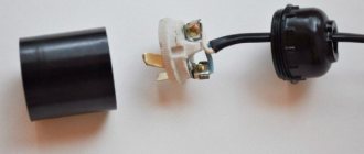
Illuminated switches are often installed in switches on carriers and extension cords, heaters and other electrical appliances. They usually have a neon light bulb with resistors built into them. I once had to repair a Pilot type extension cord in which the switch control key fell out and cracked.
When I disassembled the switch, I did not find a current-limiting resistor, which I was very surprised by. Neon bulbs must not be connected to a 220 V electrical network without current limitation. It will fail immediately. On the left photo is a view of the key from the side where the neon light bulb is installed, and on the right, the reverse side of the same switch key.
I measured the resistance between the spring and the terminal of the neon light bulb, it was 150 kOhm. This switch used an interesting design solution: two 150 kOhm resistors were installed in the key holes and a spring pressed them to the terminals of the neon light bulb, ensuring reliable contact. The springs themselves exert pressure on the movable contacts in the switch, from which, when the switch is in the On position, power is supplied to the neon light bulb.
What types of switches are there with on indication?
Illuminated Triple Switch
Illumination in electrical switches is a neon bulb or LED. Visually it is almost impossible to distinguish them; the only difference is that neon lamps consume less electricity, but create a larger voltage drop. The minimum current for LEDs to glow is 2 mA, the voltage drop is 2 V, and for neon varieties these figures are 0.1 mA and 70 V, respectively. This is important to consider when choosing an electrical switch.
Switches with an indicator may not work correctly with different types of lamps. The design works smoothly and efficiently with halogen and incandescent lamps. It is better to refuse to use LED and energy-saving ones or take special measures. The most common malfunctions are the light blinking in the off position of the switch, the indicator in the switch does not light up.
The backlight can be equipped on all types of switches and with any number of keys. The location of the glowing indicator can be different: at the top or in the middle of the key, in the center or at the bottom of the device body itself.
Where to get a neon light bulb
Neon gas-discharge bulbs (neons) are presented in a wide range and you can use any available one
Please note that on the left in the photo there is a gas-discharge light bulb with a 200 kOhm resistor, removed from a failed computer extension cord switch, which is also called the Pilot. It can be successfully installed in any switch without the additional hassle of finding components
The same light bulbs with a resistor are installed in electric kettles and other electrical appliances to indicate the on state. In the center of the photograph, a Small-sized Thyratron (triode) with a Cold Cathode MTX-90 unexpectedly appeared. To be fair, I’ll say that the MTX-90 thyratron has been shining in my sconce for decades.
Neon bulbs (neons) surround us almost everywhere. Are you surprised? All older lights use a starter, which is a real neon light bulb housed in a cylindrical housing. In order to remove it from the lamp body, you need to turn the cylinder slightly counterclockwise. There are as many starters as there are fluorescent lamps in a luminaire. In the starter, a capacitor is also connected in parallel to the neon lamp; it serves to suppress interference and is not needed in the manufacture of the indicator.
If the starter is taken from an old lamp, before using a neon bulb, do not be lazy to check it. Before installation, you must connect the light bulb according to the above diagram. It is better to take a neon from a new starter, since in old ones the glass of the bulb bulb from the inside is usually covered with a dark coating and the glow will be less visible. A light bulb from a starter can be successfully used to make your own phase indicator.
A ready-made lighting kit for installation in a wall switch can be taken from a faulty modern electric kettle. As a rule, most models have a water heating indicator. The indicator is a neon light bulb with a current-limiting resistor connected in series and this circuit is connected in parallel to the heating element. If you have a faulty electric kettle lying around in your household, then a neon light bulb with a resistor can be removed from it and mounted in the switch.
The photo shows three neon lights from electric kettles. As you can see, they shine quite brightly, so in the dark they will be visible in the switch from a great distance.
If you look closely at the insulating tubes placed at the junction of the terminals of the neon light bulb with the wires, you will notice a thickening on one of the tubes. A current-limiting resistor is located at this location. If you cut the tube lengthwise, a picture will open, as in this photo.
Resistor resistance and power
The above resistor parameters correspond to a 220 V network voltage. It happens that the LED lamp is powered from a line of a different rating. Then you will have to calculate the resistance and power of the resistor yourself.
We calculate the resistance using the formula R=∆U/I, in which ∆U is the difference between the actual voltage in the device’s power supply line and the lamp voltage, I is the LED current.
The light bulb will work normally if the resistor value is in the range of 150 - 510 kOhm.
We calculate power using the formula P=∆U×I, where the letter values are similar to the above explanations.
Knowing these formulas, it is easy to make the necessary calculations of the resistor value.
How to get rid of “blinking” lamps and possible problems
Installing a resistor in the cartridge
The main problem that owners of switches with indicators face is the flickering of the lamps and the indicator itself. Most of all, this phenomenon causes discomfort in bedrooms and the office. Improper operation will negatively affect the operating life of the switch itself and the lamp. You can get rid of the problem in the following ways:
- Give preference to LED lamps that are compatible with indicators in switches. Such lighting devices are already equipped with a soft start and a resistor. The device connects within a few seconds, so there is no flickering when the capacitor discharges. The main disadvantage is the high cost of such lamps.
- Connecting a shunt resistor in parallel will help get rid of the problem. It has no direct effect on the operating mode, but a small current will still flow through the resistor. Its power should be 2 W, and its resistance should be 50 kOhm.
- You can also connect an ordinary incandescent lamp with an energy-saving variety. In this case, the current flowing through the indicator circuit will pass through the filament. The disadvantage of this method is the large amount of electricity consumed.
- Incorrect operation may be caused by incorrect installation. For example, a mistake may result in the switch cutting off zero and not phase. This can cause not only incorrect operation, but also a short circuit. To solve the problem, just connect the switch correctly or call electricians.
Pass-through system
A distinctive feature of such mechanisms is a moving contact, which is always activated when the circuit breaks. When you press the on and off keys, it switches from one to the other, providing the functionality of the second section of the circuit.
The connection diagram for such a device is fundamentally different. One chandelier or lamp can be controlled from several different places. With its help, you can turn on the light from the bottom of the stairs, and turn it off from the top. Such devices close the circuit from different directions, acting on the lighting fixture.
Installation work will not take much time: on one side you need to install the first device, on the other end - a pass-through switch equipped with an LED. When the elements are disconnected, the light bulb will stop lighting due to the lack of a closed circuit for the passage of current. The contact closes and the lamp lights up. If you connect a second one, it will go out.
Connection features
Before connecting an illuminated switch, you must make sure that the lamp it controls is not equipped with a ballast. Such devices are present in devices for gas-discharge lamps, of which the most popular in everyday life are fluorescent lamps (fluorescent lamps).
If you connect an illuminated switch to a lamp with ballasts, the following happens: a small current flowing in the circuit gradually charges the ballast capacitor. And from time to time he initiates the ignition of the lamp, so that it flares up. This blinking will occur constantly, so you will have to abandon the indication. The only way to solve this problem is to install a resistor in parallel with the lamp with the same resistance as in the backlight circuit.
Illuminated switches work best with incandescent lamps - both regular and halogen.
Illuminated connection diagrams
There is nothing special about connecting the switch; it is done according to the standard scheme:
- Using a phase indicator (the device looks like a screwdriver with a light bulb), the phase wire is determined - it is to this that the switch must be connected.
- The line on which the work will be carried out is de-energized.
- A box is fixed in a recess in the wall.
- The internal part is installed in the box, which is connected to the wires. A contact marked with the letter “L” must be connected to the phase; controlled circuits (luminaires) are connected to contacts “L1”, “L2”, etc.
- Next, the key is installed and the switch can be used. Many models are equipped with a plate that protects the wall area around the switch from finger contamination. If such a plate is included in the kit, it must be installed according to the instructions.
Any switch must be installed in a phase break. When installing the neutral wire into the gap, it will also turn off the lighting, but in this case the lamp, even when turned off, will be energized, which can lead to electrical injury to the user when replacing the lamp.
You can make the backlight yourself and equip it with a regular switch. The indicator chain can be assembled from the following components:
- LED AL-307 (lit red);
- a resistor with a resistance of at least 100 kOhm and designed for a power of at least 1 W;
- diode KD-521 (protects the LED from breakdown by reverse voltage).
It should be noted that the given resistor resistance is approximate. It is advisable to accurately calculate it, because the amount of current flowing in the circuit will also depend on the resistance of the indicator itself and the main lamp. If you take the resistor “by eye”, then with a significant resistance of the lamp it may turn out that the LED will barely glow.
When calculating the resistance of a resistor, the following must be taken into account:
- for the LED to glow, a current of 2 mA and a voltage of 1.5 - 2 V are required;
- to glow a neon lamp requires a current of 0.1 mA and a voltage of 40 - 80 V.
The resistance of a switch-controlled luminaire can be determined with a multimeter or using special tables. In addition, many Internet sites contain online calculators with which you can select a resistor for various indicators and lamps.
The resistance value on a resistor is not always written in numbers - it can be color coded. The explanation of the color combination can be found in special tables - they are published on the Internet.
Connections of a pass-through switch with one key
The backlight consumes a tiny amount of electricity - approximately 1 kWh per month. But it can be made even more economical. To do this, use a 1 µF capacitor as a current limiter. With such a circuit, the resistor must have a resistance of 100 - 500 Ohms - it is connected in series with the capacitor and serves to limit its charging current.
The disadvantage of this solution is that the capacitor is large and cannot fit into any switch.
The button of a regular switch, unlike a backlit device, is made of opaque plastic, and in order for the homemade backlight to be visible, you need to drill a hole in it. To prevent dust from getting inside, it can be sealed with silicone.
Peculiarities
I believe that you have already personally seen, or at least a photo of, a backlit switch, because when I was a child, we had such switches in our apartment. An old Soviet model of an illuminated switch, which had a small red light on top and was hidden behind matte, barely transparent plastic. Apparently, the idea was taken from my grandparents, because they had exactly the same switches in their house, or they were installed at the same time.
In any case, as personal experience shows, it is very convenient. At that time, no one had heard of walk-through switches, and therefore in the middle of the night they had to navigate the space by memory. Or rather, I would have to, because I was lucky, and there were such switches in the house. In complete darkness, they provided enough light to understand where you were, and actually where the switch was.
Modern types of backlit switches have become more neat and sophisticated. Designs are becoming quieter and smaller in size. The same applies to LED elements. Now their main task is simply to provide information in the dark about where the switch is.In addition, there are certain restrictions regarding the areas of use of such devices. They mainly concern portable light sources, or those that receive power from low-voltage lines.
DIY illuminated switch
During the operation of electrical equipment, it sometimes turns out that in some of the rooms it would be nice to have a backlit switch. To do this, you don’t have to buy a device - you can improve your old one yourself.
What you will need for this:
- regular switch;
- LED with any characteristics;
- 470 kOhm resistor;
- diode 0.25 W;
- the wire;
- soldering iron;
- drill.
Using a soldering iron, they begin to assemble the circuit. The cathode of the diode (marked with a black stripe) is connected to the anode of the LED (the anode has a longer leg). The resistor is soldered to the positive terminal of the LED and to the wire that will serve as the connection to the switch. The second wire is connected to the cathode of the LED.
If you do not have a resistor of suitable power at hand or there is not enough space for placement, then it can be replaced with two resistors of lower power by connecting them in series (+)
Next, connect everything to the on-off mechanism. The phase conductor that leads to the lamp is connected to the terminal along with one of the wires leading to the LED. Another wire is connected to the input terminal along with the phase wire, which supplies current from the mains.
It is necessary to carefully insulate the exposed sections of the wire and prevent the conductors from touching the housing; this is especially important to do if it is metal. Check the connection diagram of the backlit switch for functionality as follows: the key, closing the contact, causes the chandelier or lamp to light up; when turned off, the LED lamp lights up
If the circuit works correctly, you can install the device in the housing
Check the connection diagram of the backlit switch for functionality as follows: the key, closing the contact, causes the chandelier or lamp to light up; when it is off, the LED lamp lights up. If the circuit works correctly, you can install the device in the housing.
To make the lighting visible, place the LED lamp into a drilled hole at the top of the housing. This is not necessary if the body is light - the light will break through it.
The switch can be illuminated using a neon lamp. The circuit uses a HG1 gas-discharge lamp and any type of resistance with a nominal value of 0.5-1.0 MOhm with a power of more than 0.25 W (+)
How to install the backlight in the switch yourself
The circuit and design of the backlit switch are simple. It is possible to assemble the device at home with your own hands. It is enough to purchase a regular switch and an LED.
The scheme consists of main parts:
- Light-emitting diode;
- limiting resistor;
- diode connected in parallel with the LED.
For LEDs, a resistor with a nominal value of 100 kOhm and a power of at least 1 W is suitable. For protection, a KD521 diode should be used.
Note! This scheme has the disadvantage of high power consumption. Its quantity can reach 1 kW per month.
To save energy, you can use another circuit that limits the LED current using a capacitor. Its capacitance should be 1 µF. When connecting the circuit, a resistor will be connected after the capacitor, limiting the charge current. This scheme has a drawback that concerns the installation process. Often capacitors are of considerable size, which can lead to difficulties with their installation in the switch.
Designs that use LEDs as backlighting work harmoniously exclusively with conventional incandescent lamps. The fluorescent lamps in such a circuit will blink after being turned off. LED lighting fixtures will not work at all, since the resistance of the lamp is always higher.
A more effective circuit with a neon lamp includes a series connection of a resistor with a resistance of 0.5 to 1 mOhm.
Installing the backlight into the switch is very simple. The LED or neon lamp must be fixed to the body using regular glue. You need to drill a hole in the key for the light.