There can be many situations when you need to connect two lamps to one power supply network using just one switch. Most often, single-key and two-key switches are used, less often - cross switches. If, as a rule, there are no difficulties connecting one light bulb, then the presence of 2 light sources forces home craftsmen to think about their correct connection to the network. However, I would like to list all the possible methods, based not only on the type of switch, but also on the types of light bulbs and methods of connecting them. Next, we will describe in detail how to connect two light bulbs to one switch, providing all the necessary installation diagrams.
Serial and parallel connection of two or more light sources
In order to connect the simplest incandescent light bulb, as in principle any other, you need to connect one contact to phase and the other to zero, the most common alternating voltage in the CIS countries, 220 volts.
Parallel connection of lighting devices means connecting two or more sources of light flux in parallel, that is, some lamp contacts are connected only to phase, and all others only to zero, as shown in Figure 1.
A current will pass through each light bulb, which will depend on its power, just as the brightness of the light flux emitted by them will also depend on the power of each lamp. Naturally, the current I will be equal to the sum of all three currents, so the cross-sectional diameter of the main conductors should be chosen according to it. This connection is considered the most common and acceptable, since it will be possible, if necessary, to add light sources in the future and they will not affect those already installed.
With a series connection shown in the figure, the current flowing through one light bulb will depend on the power of each light source, and the voltage on them will be divided by the number of lamps and, for a given input voltage of 220 volts, will be equal to 110 volts on each light source.
This connection must be made with lamps that have equal power. This can be seen using the example of two incandescent lamps. Since if you connect one lamp of 20 Watt, and another, for example, of 200 Watt, then the lamp with a lower power will immediately fail, since the same current will pass through it as in the second lamp with a power of 200 Watt, and this is 10 times its face value. This connection can be used to increase the service life of incandescent lamps, for example, in entrances and staircases. By connecting two lamps of 220 volts and a power of, for example, 60 watts each, they will burn at half power and will last a very long time. Please note that this is only possible when connecting incandescent lamps. Connecting two or more LED lamps (luminaires) and energy-efficient lamps in series is not practical, since they already have a fairly long service life.
Connecting a lamp to one switch or several
How to connect a lamp through a switch? The main nuance when connecting is that the neutral power wire is directly connected to the 220 volt network, and the phase is broken through the switch. This is done so that you can safely solve problems with the lamp socket by turning off only the switch. If two switches are connected in series, then only when both keys are pressed will the lamp light up. These types of connection of light switches are very rarely used, only under certain individual conditions.
More interesting is the connection of the so-called pass-through switch.
The essence of this circuit for connecting one lamp is that the lamp can be turned on and off from both the first and second switches, regardless of the position of each of them. For example, this is convenient, say, in a long corridor, when entering it, a person presses the switch key 2, and calmly walks along the illuminated room, having reached the end of the corridor, there is no need to return to turn off the light, but he can lightly press switch 1, installed at the end corridor, turn off this light source. With this connection, the phase also passes through the switches.
Improving lighting by installing a motion sensor
The main function of installing a motion sensor and connecting it to the lighting system is to automatically turn on the lighting without pressing the light switch button. That is, a person entered the room or into the sensor trigger zone and the light turned on; after leaving, the light turned off on its own (automatically). When choosing a motion sensor, you must first take into account the maximum power of the lighting lamps.
The connection diagram for the motion sensor is also not particularly difficult. It can be installed with or without a switch. Simply, when the switch contact is turned on, the motion sensor is removed from the lighting network, and the lighting device is turned on directly without a sensor.
In any case, when working with voltage, be sure to comply with safety requirements, and in particular:
- check the presence and absence of voltage on live elements that a person touches during installation;
- lighting power supply circuit breakers must be locked;
- carry out work with proper tools.
A little theory
A procedure such as installing and connecting a chandelier requires certain knowledge about the switches and wires that you will have to work with.
Connecting a chandelier to a double switch, rather than to a single-key switch, is inherent in the design of the lighting fixture itself. Three wires (with painted or white insulation) coming from the ceiling also indicate this.
A bundle of multi-colored wires, including those coming from the purchased chandelier, carries certain information.
In the EU, color marking of wires is established by the IEC 60445 standard of 2010, in the Russian Federation - by GOST R 50462 of 2009. She looks like this.
The wiring of the electrical network with cables for domestic premises of the NYM, VVG, VVGng (non-flammable) brands in a modern private house also complies with these standards. If this is not the case, then the network needs to be called - to determine the purpose of the cores of a two- or three-wire wire.
This is done using a screwdriver with a phase indicator light. The phase conductor lights up the LED in the screwdriver. Recording the result with a colored permanent marker or colored electrical tape is mandatory.
For lighting, a cable with 3 conductors with a cross section of 1.5 mm2 is laid. The cross-section of the neutral and phase conductors must be the same. Advantage is given to copper wires: they have greater electrical conductivity, do not oxidize, are durable, and flexible. If before connecting a new chandelier it is possible to replace the aluminum wiring with copper, it is worth doing.
The maximum power of the lighting device should not exceed the value indicated in the table. Information is contained in the instructions for the chandelier, the presence of which is required.
A safety margin (subtract 20% from the received power) will not hurt. The goal is to insure against wires of smaller cross-section and low-quality copper. With old wiring, such caution is more than justified.
You also have to connect the wires (of the same metal) coming out of the ceiling with the wires of the chandelier. Conventional twisting using pliers is not even considered (prohibited by clause 2.1.21 of the PUE). Working with a soldering iron under the ceiling is a dubious pleasure, and not everyone can do it.
The owner of a private house must have blocks, PPE, NShVI tips, a clipper or self-clamping terminals.
When an aluminum wire comes from the ceiling, and a copper wire comes from the chandelier, they should be connected only using terminal blocks, walnut clamps or WAGO self-clamping terminals with Alu-plus paste.
In the future, the word “connect” means just such a connection of wires to each other. Of course, all work with devices and wires must be done with the network turned off in the room.
Subtotal: we have theoretical information, modern materials, and tools.
Application of junction box
Cables and wires do not go directly from the panel to electrical appliances, from switches to light bulbs. All outgoing and incoming lines of electrical equipment are found in specific installation units called branch boxes. There they communicate in a certain way.
The following article will introduce you to the rules for installing junction boxes, also called junction boxes, branch boxes, or in electricians' slang, junction boxes. We recommend that you read the useful material.
Most often, boxes have empty space inside. The wires of different lines are then connected to each other using twists. To ensure reliability, it is recommended to treat the tails of the connections with special welding. Copper conductors can simply be soldered.
Before laying inside, open contacts are insulated from each other with cotton tape. You can screw special insulating clamps onto the twisted wires. Here, insulating tape is no longer needed.
If the box is equipped with screw terminals, the contacts are then made using them. Such devices allow you to connect aluminum and copper conductors. Clamp terminals can be used, but this is only if there is sufficient space for laying the ends of the wires connected by them.
Installation Safety Precautions
Here is a set of some standard rules to avoid trouble when installing lighting fixtures:
- The switch cannot be set to “zero”; it must always break the “phase”. Only in this case the switch is in the “off” position. allows you to carry out any repair work on the lamp, including replacing it, without cutting off power to the entire house.
- When making a twisted connection of wires in a junction box, under no circumstances should aluminum and copper wires be connected to each other. Metals with different potentials form a galvanic couple; the contact will weaken over time and begin to “spark.” Sometimes this leads to fires.
- Before starting work, you should stock up on a tester to determine the phase wire and, just in case, thick rubber gloves.
- You should not cover open wiring (either double insulated or triple insulated, it doesn’t matter) with paper wallpaper or other flammable finishing materials.
- Do not use used wiring. It is unknown what loads it was subjected to in the past, and it is impossible to check the condition of each core inside the braid along its entire length.
Transmitter connection option
Instead of connecting two light bulbs to a 220 V network, you can connect lighting fixtures to the network using 12 V frequency converters. Such devices conduct electric current to several lamps with a short pause of 1-2 seconds. At the same time, lighting devices receive electricity smoothly, without a sharp increase in load.
When can you connect the converter:
- for supplying current to incandescent lamps;
- for providing electricity to halogen light bulbs.
The switch is installed in the circuit before the converter. Otherwise, the contacts may burn out. This should happen because the current is greater at low voltage. In addition, the converter provides a slight delay in the incoming voltage. If a breaker is added after the switch, then the gradual, smooth start of the light bulbs will not be ensured. Thus, the whole point of including the converter in the circuit is lost.
If a two-key switch is mounted, then you will need to connect 2 converters. Power will have to be supplied to it through a second line. “Zero” will remain common.
Serial connection
You can connect spotlights in series, although this is not the best solution. Despite the fact that this type of connection requires a minimum number of wires, it is practically not used in everyday life. This is because it has two significant drawbacks:
- The lamps do not glow at full strength because they are supplied with reduced voltage. How much reduced depends on the number of connected light bulbs. For example, if three lamps are connected to 220 V, you need to divide by 3. This means that each lamp receives 73 V. If 5 lamps are connected, divide by 5, etc.
Series connection principle
It is for these reasons that this type of connection is used exclusively in Christmas tree garlands, where a large number of low-power light sources are collected. You can, of course, use the first disadvantage: connect 18 or 19 12 V light bulbs in series to a 220 V network. In total they will give 220 V (with 18 pieces 216 V, with 19 - 228 V). In this case, you don’t need a transformer, which is a plus. But if one of them burns out (or even the contact deteriorates), it will take a long time to find the cause. And this is a big minus that negates all the positive aspects.
Diagram of serial connection of light bulbs (spotlights)
If you decide to connect spotlights in series, this is easy to do: the phase bypasses all the lamps one after another, zero is supplied to the second contact of the last bulb in the chain.
If we talk about the actual implementation, then the phase from the distribution box is supplied to the switch, from there to the first spotlight, from its second contact to the next... and so on until the end of the chain. The neutral wire is connected to the second contact of the last lamp.
Diagram of sequential connection of spotlights via a single-key switch
This scheme has one practical application - in the entrances of houses. You can connect two incandescent light bulbs in parallel to a regular 220 V network. They will glow incandescently, but will burn out extremely rarely.
Wiring continuity
It is not possible to identify a grounded wire in every home. In old buildings they are usually absent. The remaining contacts are also not always marked. To figure out where the “phase” is and where the “zero” is, it is necessary to carry out a dialing.
So, with a two-key switch device, you may need to connect a chandelier with three wires, two of which will be phase, and one will be neutral. To determine the voltage, you need an indicator screwdriver, a tester (multimeter) or a voltmeter.
During the call, the switch key must be in the “ON” position; accordingly, the electricity in the room must also be connected. Upon completion of the work, it is necessary to switch the key to the “OFF” state and turn off the machine on the control panel or unscrew the plugs.
Voltmeter
One of the measuring instruments often used by craftsmen to determine voltage is a voltmeter. Its main advantage is its ease of operation, as well as the absence of the need for an additional power supply (batteries). When working with it, you must remember that its operation must be carried out parallel to the source of electricity and it must be in a strictly horizontal position.
Determining contact voltage using a voltmeter is a simple task. It is enough to fasten the probe wires to the contacts and track the position of the arrow on the indicator. If the value does not change (is at zero), then both wires are phase, and the remaining wire is zero. Then you should move one of the probes to “0”, and the second one in turn to each of the “phases”. The arrow on the device should indicate a value of 220 V. To facilitate further work, it is necessary to mark each wire with a colored marker or Latin letters, where “N” is the neutral contact, and “L” is the phase contact.
Other schemes
Sometimes there is a need to connect 3 light bulbs to a two-key switch. In this case, the circuit provides that two lamps will be powered from one key, and a third from the other.
The peculiarity here is not only that everything is connected in the junction box, you also need to connect the light bulbs correctly.
In general, the connection diagram for three lamps does not differ from that described above (all connections in the junction box are the same as when connecting two lamps to a two-button switch).
The only thing is that one of the created branches will have to be divided between two lamps.
That is, each of the two cartridges will have to be connected to a phase and neutral conductor. How to do this is shown in the diagram.
The same feature applies to the circuit for connecting two lamps to a single-key breaker.
That is, the whole feature of creating a branch comes down to making a phase and zero connection to two cartridges.
It is not necessary that there be one or two lamps connected to one key. Below are several connection diagrams that assume the presence of 3-5 lamps.
The first of them is with a single-key switch:
The second scheme is with a two-key switch and a large number of lamps:
Read here: How to properly install electrical wiring.
As you can see, all the diagrams are similar to each other, so making the lighting connections correctly should not be difficult. But the main thing is compliance with safety regulations.
Common mistakes
Often, inexperienced electricians lower the neutral conductor to the switch along with the phase conductor, and then ask questions about where to connect it. In fact, there is no need to pull the neutral wire to the switch . And even more so, there is no need to break it with a switching element. It must go through the box in transit, laid parallel to the earth conductor.
Another common mistake when connecting a double switch is connecting the phase conductor not to the terminal common to the two contact groups, but to one of the outgoing ones. In this case, only one group of lamps will light up. This error is easy to spot and correct.
Other errors that lead to the inoperability of the lighting circuit, in most cases, occur due to inattention and are associated with incorrect connection of electrical wires. To eliminate such problems, you need to check the diagram more often (especially if you have no experience).
Otherwise, connecting a chandelier should not cause any problems if you know the basics of electrical engineering.
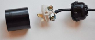
Switch device
The main element of the switch is the working part, mounted in the socket box. It is a metal structure with an attached drive. The drive is used to turn the device on and off. The drive is a moving contact that closes and opens an electrical circuit between two static contacts.
The first contact is called incoming: it is connected to a phase from the mains. The second contact (outgoing) is connected to the phase conductor coming from the lighting device. When the switch is positioned correctly, both fixed contacts are initially in an open state. When you press the device button, the moving contact provokes the closure of both fixed contacts. As a result, current flows through the closed circuit of their electrical network to the light bulb, and it lights up.
To ensure safety, the working part of the switch is housed in a housing made of dielectric material. The cases are made of plastic or porcelain.
Other components of the switch are the frame and keys. These elements are usually made from plastic. The keys are fixed on the drive of the working part. Moving as a result of pressing, the key changes the position of the contact, which leads to turning the light on or off.
The frame is designed to prevent a person from accidentally touching the switch contacts. In other words, the frame acts as a barrier between the energized elements and the person. The frame is fixed with screws or latches made of plastic.
The only difference between a two-key device and a single-key device is the presence of a pair of output contacts. Each contact is connected to a phase conductor of one of the lamps.
Separate lighting
A similar scheme is often used in office buildings, where it is necessary to separately illuminate many local areas. The separate lighting scheme is not particularly complicated, although it requires special knowledge.
The switch is placed in a phase break. The devices are equipped with one input and two output voltage contacts. The phase wires after the switch go to the lighting fixtures. The neutral conductor will be common to all light sources in the room.
As a result, pressing one of the keys turns on only the devices connected to a specific phase. Other light sources do not turn on.
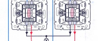
Scheme with a two-key switch
Before connecting the wires into the circuit, you must have the following installed:
Two lamps for one bulb. For example, one in the kitchen, the second in the hallway. Distribution box under the ceiling (15-30 cm below the ceiling level). If the room already has a distribution box, you can use it. The main thing is that there is not a lot of switching and that it is convenient for you to work. Socket box for two-button switch. As a rule, it is installed at a distance of 90-100 cm from the floor level. Wires must be laid in grooves between all these elements
Please note that in the case of a two-key switch, a three-wire wire must be connected to it from the distribution box.
Now we need to connect all this electrically so that voltage comes from the power source to the light bulbs.
Two strands of wire from the supply network come into the distribution box - zero and phase. Using an indicator screwdriver, identify the phase conductor. Touch both wires one by one with a screwdriver. If you touch zero, the indicator window will not light up. If the window lights up, it means you have found a phase conductor. Carefully mark it with insulating tape.
Now to make connections, turn off the power to your workplace. You need to turn off the circuit breaker that supplies voltage. Nowadays, in many houses and apartments, entire panels are installed, in which there are circuit breakers that turn off each room. If you don’t have one yet, then you’ll have to turn off the water machine for your apartment. Check that there is no voltage and get to work.
Three strands of wire are inserted into the socket box. Strip off the insulating layer on them by 1 cm (this is done with a knife). Connect one core to the incoming contact of the switch, connect its second end in the distribution box to the phase wire of the power supply network. Connect the other two wires to the two output contacts of the switch. Accordingly, connect their second ends in a distribution box with phase conductors from one and the second lamp.
Now you can place the working part of the switch in the socket box, fix it, install the protective frame and keys.
There will be one more connection in the distribution box; connect the neutral conductors coming from the lamps to the neutral from the supply network.
The lamp sockets have two contacts - one side for connecting the neutral conductor, and a central one, the phase is connected to it. Make these connections.
Check that all contacts are reliable, but we advise you to insulate the twisted areas after you are sure that the switch is working correctly. To check the assembled circuit, apply voltage to the apartment (that is, turn on the input circuit breaker). Both keys of your switching device are in the off position, the lights in the kitchen and in the corridor are not lit. Press one key - the light in the kitchen comes on, turn on the second - light appears in the corridor. Also, turn off the first and second keys one by one, the lights went out first in the kitchen, then in the hallway. Everything works correctly.
Turn off the input circuit breaker again and insulate the places of twists in the distribution box with insulating tape; you can also put PVC tubes on top.
The circuit with a double switch is discussed in detail in this video:
Preparatory work
No matter how many keys your switch has (one, two or three), the preparatory work will be the same.
To begin with, you need to install a general distribution box and a mounting box for the switching device in the room; it is also called a socket box:
- If the walls in your room are made of PVC, plasterboard sheets, wood or MDF panels, install a special bit with serrated edges on a drill and make a hole. Insert the mounting box into it and fix it to the wall using self-tapping screws.
- For concrete or brick walls, make a hole using a hammer drill or drill with an attachment that works on concrete surfaces. But in this case, the mounting boxes must also be fixed using gypsum or alabaster mortar
As a rule, the installation of holes is carried out simultaneously with the laying of grooves. This is done purely for aesthetic reasons; there is a lot of dirt from such construction work, and it’s better to spray it once and clean it up. Grooves are grooves in the wall surface into which connecting wires will then be laid. They can be done using various tools:
- Hammer and chisel. This is an old ancestral method, its advantage is the complete absence of costs for purchasing tools (every man has a hammer and chisel). The disadvantage of this method of gating is that it takes a lot of time and effort.
- Bulgarian. This tool is often called the worst of the best. It’s convenient that grooves can be made quickly and without much effort. But it is from the grinder that there is a lot of noise and dust, and besides, it is not possible to make grooves of the same depth along the entire length, and it is almost impossible to work with the grinder in the corners of the room. So choose such a power tool as a last resort.
- Hammer. All you need is to purchase a special attachment for it - a strober or a spatula. In all other respects there are no shortcomings, it’s fast, convenient, the grooves are more or less even.
- Wall chaser. This is the ideal tool for this type of work. Works efficiently, safely and quickly. The grooves are smooth, there is no dust, since the wall chaser is connected to a construction vacuum cleaner. They are comfortable to work with and the tool does not make much noise. The only drawback is the high price. But there are services where you can rent a wall chaser.
Briefly about gating walls using the tools listed above is described in this video:
It is necessary to lay two-core wires into the grooves and fix them with cement or alabaster mortar.
So, the preparatory work is completed, the boxes are mounted, the wires are laid, and you can connect the light bulbs and switch.
Connection diagram of a single-key switch to a light bulb
First of all, power must be supplied to the circuit breaker. After this, the connection diagram for the switch and light bulb is carried out in stages. The wires in the cable used are usually blue and black, as well as yellow with a green stripe on it. The blue wire is used for zero, the yellow wire is for grounding, and the black wire is for phase. The colors of the wires for all connections must be observed in a certain order. The stripped wires are inserted into the contact terminals and clamped with special screws. All other nodes are connected in the same way.
When connecting the lamp, preparation is also carried out with wire. In this case, grounding is not used, but only the neutral and phase wires are used. After preparation, the wires are connected directly to the socket and to the switch. After this, the diagram takes on a finished form.
To check the functionality of the circuit, you need to screw a light bulb into the socket. Voltage is supplied to the circuit breaker, after which it turns on. The correctness of all connections is first checked by an indicator. After pressing the switch button, the light should light up, which means that the entire circuit is completed correctly.
Difference between parallel and series connection of lamps
If any light bulbs are connected in parallel to each other and, accordingly, in series with the switch, then the voltage on each of them will be equal and in this way light sources of different powers can be connected. The main condition is that the operating voltage at which they operate normally must be equal to the voltage of the power source. If in this case a step-down device with a rectification system is used, then the opening contact must disconnect the circuit in front of the converter, as shown in the figure.
In this case, it does not matter whether two or three light sources will be turned on. Most often these are halogen and LED lamps, designed for a reduced voltage of 12 or 24 Volts.
With a serial connection the situation changes dramatically. The supply voltage will be divided by the number of light bulbs, that is, if the network is 220 Volts, then on two artificial light sources connected in a series circuit, the voltage will be approximately 110 Volts. This must be taken into account when choosing and purchasing them. Another nuance with this connection is related to the power of each of them. It should be the same or as close as possible to each other, because With such a connection, the current is the same in all parts of the circuit. If one lamp is 500 W and the other is 50 W, then the lamp with the lower power, connected by one wire to each other, will still flow more current, corresponding to the most powerful load. A light bulb with less power will burn out instantly. This rule applies to all types of lamp sources, from incandescent to LED.
If you need to connect an LED light source from the network or from sockets, it often consists of a so-called driver installed inside the light bulb housing. It performs several functions at once: rectifying and reducing. These lighting devices are not intended for serial connection, only for parallel connection.
For fluorescent daylight sources, both with an electronic starting device and a starter, a series connection is most often found in raster lamps, as it allows one choke and two starters to ensure stable operation. In this case, the starter itself is selected for 127 V with the calculation of the operating voltage of a standard 220 Volt network. The switch in this circuit uses a regular single-key switch and also breaks the phase wire with its contact.
As for the parallel connection of several fluorescent lamps or compact lamps, the operation of which is based on the glow of a phosphor applied to a glass tube, then in this situation it is possible to connect any number to one switch, either single-key or two-key. The main thing is to take into account the power of all light sources, on which the current in their circuit directly depends. For any switch it is limited and indicated in the technical data sheet, on the packaging or case. If, for example, a current of 5 A is specified, then you should not exceed its value, since this will very quickly render the breaking contact itself unusable.
To fully understand the serial and parallel connection of light bulbs, we recommend watching the video:
Safety regulations
To ensure that no unforeseen situations arise during the installation of a two-key switch, you must try to follow basic safety precautions. They will help avoid any injuries and reduce the likelihood of device failure.
Basic safety rules:
- Any work with electricity should only be carried out by people with sufficient knowledge and experience. Otherwise, the likelihood of any injury will increase significantly.
- Measures to install the switch can only be carried out after turning off the power supply to the room. At the same time, care should be taken to ensure that no one accidentally turns on the electricity.
- Before touching exposed wires, you need to check them with a special indicator screwdriver for the presence of voltage.
- It is forbidden to touch two bare wires with your hands, even if they are disconnected from the power supply.
- Do not touch the wires with wet hands. The same applies to other structural elements capable of conducting electric current.
- Any preventive, installation or repair measures can only be carried out using tools equipped with insulated handles.
- Experts recommend carefully isolating all potentially dangerous places. This simple action will help avoid accidental contact of contacts, which will cause a short circuit.
- It is prohibited to turn on the power supply in the room until the installation work is completed.
- Clothing and shoes should not create discomfort or distract the technician from the installation process.
- When testing an installed switch, you should be extremely careful and remember the safety rules.
Thus, almost anyone can install a two-key switch. And provided you follow the advice of professionals and safety regulations, everything will go quickly and smoothly.
What's the end result?
If you thoughtfully approach the issue of connection, then such work will not pose any special difficulties. The main thing is not to neglect safety issues when carrying out electrical installation work. It must be remembered that all work is carried out only with the voltage turned off, because 220 volts is a dangerous current, the shock of which can lead to death or serious damage to the body.
If there is even the slightest doubt that self-installation is possible, it is better to seek help from a specialist. After all, if the quality of the connections is poor, the wiring may catch fire and, as a result, a fire in the house or apartment. Therefore, as they say, “measure twice, cut once.”
Two lamps per switch
Connection diagram for several light bulbs to a switch:
- De-energize the system. We connect the stripped wires to the contacts carefully, in accordance with the principles outlined above.
- The junction box receives zero and phase from the general network. The zero coming from there must pass through all the lamps. We bring it directly to the lamps, bypassing the switch.
- The phase passed through the switch is sent to the central contacts of the bases. It comes from the network into the distribution box and passes through the input on the switch.
- The phase is then output through the outgoing contacts on the device.
- From there we send the phase to go through two lamps. We remove it from the switch through two separate cables.
When constructing a circuit, it is necessary to calculate the total power of the light bulbs. Each of them must be marked indicating the maximum load limit.
To securely fasten the contacts, you need to use screw or spring type terminal clamps.
You should not try to connect different types of metal together. Copper and aluminum, once twisted, will begin to oxidize. As a result, the contact will overheat and become loose.
Wire marking
There is no single international standard regarding color marking. The exception is the grounding cable, which is painted yellow-green and has the Latin designation “PE”. Depending on the country of origin, the markings of the remaining wires may differ. Most often, the phase is designated by the letter “L”, and the zero or working contact – “N”.
You can locate the required cable using different types of measuring instruments or a voltage indicator screwdriver.
Switch device
The working part of the switch is a thin metal frame with a drive installed on it. The frame is mounted in a socket box. A drive is an electrical contact, that is, a device on which electrically conductive wires are connected. The drive on the switch is movable, and its position determines whether the circuit is closed or open. When the circuit is closed, the electricity is on. An open circuit makes it impossible to transmit current.
The drive provides electricity or an obstacle to the path of the signal transmitted between two fixed contacts:
- the input contact goes to the phase from the electrical wiring;
- the outgoing contact is connected to the phase going to the lamp.
The normal contact position on the actuator implies that the commutator is off. The fixed contacts are open at this time and there is no lighting.
Pressing the control button on the switch completes the circuit. The moving contact changes its position, and the fixed parts become connected to each other. Along this path, the voltage network transmits electricity to the light bulb.
To ensure the safety of the system, the working part must be placed in a housing made of materials that are not capable of conducting electric current. In the switch such materials can be:
Other design elements directly protect the user:
- The control key allows you to change the state of the circuit with one touch, closing and opening it at the request of the person. As a result of a light press, the light in the room turns on or off.
- The frame completely insulates the contact part, which eliminates accidental touches and electric shocks. It is attached with special screws, and then sits on hidden latches.
Plastic is effectively used as the main material for their manufacture.
Safety conditions
Installation of pass-through switches is possible with both open and hidden wiring systems.
Installation can be carried out independently, only if you follow the necessary safety rules:
- Before starting installation work, it is necessary to turn off the power to the apartment.
- It is necessary to correctly determine the location of the phase and zero.
- The wires should be connected by neat twisting, while crimping and insulating them.
- It is recommended to firmly fix electrical accessories and branch boxes to surfaces.
- Based on the power of electricity consumed, you need to determine the power parameter of the lighting device and select a three-core cable of the required cross-section.
Due to a design feature, the keys of backup electrical switches do not have a specific “on” or “off” position. Based on the position of the electrical contacts of the other switch, the two connecting nodes of this system correspond to the “closed” or “open” position. Therefore, when the light is turned off, the key will be in a different position each time. This feature is not a problem - you can quickly get used to it.
Types of lamps for home use
Tube progress keeps pace with switches. Their diversity is also impressive.
But here, too, some more popular types are defined:
- Incandescent light bulbs are established home light sources in a round glass bulb with a vacuum and a tungsten filament inside.
- Halogen lamps are the same incandescent lamps filled with a special gas. It increases service life and minimizes the size of their flasks. Disadvantage: When installing, you cannot touch the glass of the flask with your hands.
- Fluorescent fluorescent lamps are not very common at home, but they are also traditional lighting devices (hereinafter simply “fluorescent lamps”).
- Energy-saving LED lamps, as the name suggests, use the glow of groups of LEDs. They can be fixed into ordinary screw-in sockets (hereinafter simply “LED lamps”).
Energy-saving fluorescent light bulbs are increasingly replacing the usual ones. The operating principle is similar to fluorescent lamps. They are screwed in like incandescent lamps (hereinafter simply “energy-saving lamps”).
A few words about electric current
Without “loading” with theory and complex physical concepts, let us recall the elementary basics of electrics. The household electrical network has a voltage of 220 V, the type of current is alternating. What does it mean? One of the contacts, “phase,” has a constantly changing potential from “+” to “−” (50 cycles per second), and the other “zero” serves as a kind of battery, allowing electrons to either accumulate in excess or flow back.
Each lamp has two contacts: base and central. In order for our lighting device to start working, zero and phase must be connected to these two contacts. Moreover, in the case of alternating current and a regular household lamp, polarity does not play any role.
But it is still necessary to know the location of “zero” and “phase”. There is a special device - a “probe”, which is used to determine which of the wires is phase. This must be kept in mind for the correct inclusion of a disconnecting device - a switch - in the circuit. It must necessarily break the “phase”, these are the safety requirements.
Halogen chandeliers, including those with remote controls
Halogen light bulbs are designed for a voltage of 12 V, so 220/12 V voltage converters are installed in such chandeliers. As a rule, the control circuit is assembled and only 2 wires can stick out of the chandelier, even if the chandelier is controlled by a remote control.
These two conductors are connected to the electrical wires in any order, although the terminal block may be marked with the letters "N" and "L". In addition, there may also be a grounding conductor.
The following video shows how to connect a chandelier with a remote control.
Connecting a chandelier with halogen lamps