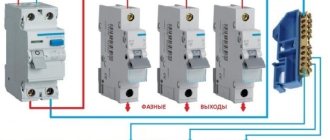
The installation of residual current devices (RCDs) is an additional and essential means of protecting people from electric shock and an excellent device that prevents fire from faulty electrical wiring. This is due to its ability to record the difference in currents flowing in the phase and neutral wires. Therefore, if the wire insulation is broken or the neutral wire is broken, the RCD will definitely disconnect the protected section of the electrical network. In this case, the overload and short circuit protection circuit breakers will not react. The installation of RCDs in houses and apartments where there are small children is especially relevant.
Purpose and scope of RCD
The RCD is designed to compare the amount of electric current flowing in the phase and neutral wires. During normal operation of electrical appliances, this value is the same and the counter currents in the RCD windings compensate each other. As soon as an emergency situation occurs - the insulation is broken somewhere with the subsequent flow of charged particles to the ground, bypassing zero, the differential currents will differ and the protection will turn off the power.
In practice, this can be represented as follows: if the electrical wiring breaks down on the body of a washing machine or water heater, their body will be at potential. As soon as the potential begins to flow from the body to the ground, the protection will react and the person will not be harmed. It is most important to connect an RCD to a circuit of powerful appliances in the kitchen or bathroom, because of the release of condensation on their surface and metal body, which is a potential conductor.
But this does not mean that other equipment does not require similar devices for protective shutdown: the same lamps, sockets and other connected loads can also pose a threat to humans. Therefore, it is also important to connect them to the RCD on the panel, both common for all electrical wiring, and separately for any devices or their groups. Features of the use of electronic and electromechanical RCDs directly depend on the power supply circuit and the location of their installation.
Selecting a protection device
Based on the above characteristics, an RCD is selected, but do not forget to take into account the conditions of the bathroom (high humidity).
Give preference to type “A” devices, which respond to alternating and direct current. Despite the fact that sinusoidal alternating current flows in our electrical network, modern household appliances are equipped with special power supplies based on electronic semiconductor elements. Due to this, the AC sinusoid in the power supply is converted into a pulsed half-cycle. And if the leak is of this nature, then a cheaper “AC” type device will not react to it and will not work.
Carefully consider the passports for the washing machine and water heater when you are planning to buy an RCD.
It is for equipment installed in the bathroom that manufacturers indicate the type of device required, most often it is “A”.
Some differential circuit breakers have an additional block in their design, with the help of which consumers are disconnected in the event of a break in the neutral wire in the network.
For household appliances in bathrooms, it is recommended to install an RCD with a rated differential current of 10 mA. According to the time-current characteristic parameter, type “C” is preferable.
If you are not sure that you can choose a protective device yourself, then go shopping at retail chains that have a good reputation. Qualified sales consultants will provide you with the necessary assistance, tell you which manufacturer to choose, and select the appropriate device according to your financial capabilities.
Connection diagrams for RCDs in a single-phase network
Most household consumers are powered by a single-phase circuit, where one phase and neutral conductor is used to supply them with electricity.
Depending on the individual characteristics of the network, single-phase power supply can be provided according to the following scheme:
- with a solidly grounded neutral (TT), in which the fourth wire acts as a return line and is additionally grounded;
- with combined neutral and protective conductor (TN-C);
- with separated zero and protective grounding (TN-S or TN-CS; when connecting devices indoors, you will not find any difference between these systems).
It should be noted that in the TN-C system, in accordance with the requirements of clause 1.7.80 of the PUE, the use of differential circuit breakers is not allowed, except for the protection of individual devices with the obligatory combination of zero and ground from the device to the RCD. In any situation, when connecting an RCD, the characteristics of the supply network should be taken into account.
Without grounding
Since not all consumers can boast of having a third wire in their wiring, residents of such premises have to make do with what they have. The simplest circuit for connecting an RCD is to install a protective element after the input circuit breaker and the electric meter. After the RCD, it is important to connect circuit breakers for different loads with the corresponding shutdown current. Please note that the operating principle of RCDs does not provide for disconnecting current overloads and short circuits, so they must be installed together with circuit breakers.
Rice. 1: Connecting an RCD in a single-phase two-wire system
This option is relevant for apartments with a small number of connected devices. Since if there is a short circuit in any of them, shutting down will not bring any noticeable inconvenience, and finding the damage will not take much time.
But, in cases where a sufficiently branched power supply circuit is used, several RCDs with different operating current values can be used.
Rice. 2: connecting an RCD in a branched single-phase two-wire system
In this connection option, several protective elements are installed, which are selected according to the rated current and operation current. As general protection, an incoming 300 mA fire protection RCD is connected here, followed by a neutral and phase cable to the next 30 mA device, one for sockets, and the second for lighting; a pair of 10 mA units are installed for the bathroom and nursery. The lower the response rating is used, the more sensitive the protection will be - such RCDs will operate at a significantly lower leakage current, which is especially important for two-wire circuits. However, it is also not worth installing sensitive automation on all elements, since it has a high percentage of false positives.
With grounding
If there is a grounding conductor in a single-phase system, the use of an RCD is more appropriate. In such a scheme, connecting the protective wire to the device body creates a path for current leakage if the insulation of the wires is broken. Therefore, the protection will operate immediately in the event of damage, and not in the event of electric shock to a person.
What mistakes should you avoid?
Before connecting, be sure to double-check the technical specifications of the devices. The rated current must be equal to or higher than the same parameter for the input circuit breaker. The values can be easily determined by the markings.
Electricians recommend choosing a protective device one step higher, that is, for a 50A circuit breaker, a 63A RCD is suitable.
You can correctly calculate the parameters, choose a machine and an RCD with the correct rating, but make a small mistake during installation, as a result of which the system will be useless.
For example, beginners often confuse tires. It should be remembered that I use different buses for the neutral conductor and the ground wire. In addition, each device requires a separate bus: for 5 RCDs - 5 buses.
Whatever connection scheme you use, the grounding conductor will not participate in it. All terminals are designed either for the phase wire (load) or for the zero wire (neutral)
In no case should the poles N and L be confused . They have letter designations on the body, and the wires differ in color, so you need to be careful.
If a false alarm occurs or, on the contrary, the device does not respond, the reason may be the following:
- “phase” and “ground” are connected after the RCD;
- incomplete connection - conductor N is not inserted into the corresponding terminal;
- “zero” and “ground” are connected in the socket;
- confusion between connecting two or more RCDs to electrical installations.
In practice, there are many more errors, since different schemes are used. The more devices are involved in assembling the electrical panel, the more careful you need to be when connecting.
Connecting an RCD in a two-phase network
Two-phase power refers to non-standard connections, where a converted old-style 127 V transformer was reconnected into a triangle for modern 220 V consumers, which are powered by linear voltage from it.
Rice. 4: Connecting an RCD in a two-phase system
To connect a residual current device to a two-phase circuit, it is necessary to disconnect both wires at the input to the panel, since each of them is under potential. Then each of the phases is connected to the corresponding phase terminals and neutral terminals, further observing their polarity. Unlike a single-phase system, circuit breakers at the output of the RCD must be installed for each line, or they can be replaced with one two-pole one.
Connection methods
There are four known connection options:
- Connecting a two-pole to a single-phase network.
- Connecting a four-pole to a three-phase network using a neutral.
- Connecting a four-pole to a three-phase network without using a neutral.
- Connecting a four-pole in a single-phase network.
Let's consider each case separately.
Connecting a two-pole RCD to a single-phase network
Two-pole RCD for single-phase network
Among all the listed connection methods, this is perhaps the most common scheme. When it is connected, there are no complex turns. Moreover, such a device can be connected independently. To do this, you need to find out on the case or in the passport exactly where the neutral or zero is located on the machine, as well as the phase. As a rule, the following signs are indicated on the machine: 1, 2 and N. 1 means an incoming phase conductor, 2 means an outgoing phase conductor and N means zero or neutral.
One of the main conditions for connecting such an RCD is that it is installed in all cases after the circuit breaker! This requirement allows you to protect the electric meter from an increase in current.
There have been cases when the device failed. Why? The whole point is that a current exceeding its rated operating current passed through it. To prevent this from happening in your case, buy a device with as high a rated operating current as possible. Moreover, it is important to follow the correct sequence when connecting. Otherwise, problems may arise during its operation. For example, if you confuse the zero and phase terminals when connecting, the device will immediately fail.
Connecting a four-pole RCD to a three-phase network using a neutral
Four-pole RCD three-phase network, neutral
This connection method is also quite common. The principle of its connection is practically no different from a single-phase network. Only in this case is a four-pole RCD installed. It has four incoming wires, which are designated on the machine as A, B, C and zero (N). As a rule, the connection diagram is indicated on the machine body. The only difference may be that on a four-pole device the zero may be on the other side. The most important thing is to connect the outputs and inputs correctly.
Such RCDs are used to protect electrical wiring from fire at high leakage currents. If used to protect against electric shock to a person, it is recommended to use a leakage point that is between 10 and 30 mA.
To protect the device itself, a circuit breaker is mounted directly in front of it.
It is best to connect single-phase networks using a zero busbar, which is mounted directly in the panel on a DIN rail.
Also, when connecting, it is extremely important to observe the color marking of the wire, as well as the connection of the neutral and phase conductors.
Connecting a four-pole RCD to a three-phase network without using a neutral
Connection to a three-phase network without neutral
This circuit is used in most cases to connect three-phase electric motors. The machine will disconnect it from the network as soon as a slight short circuit occurs in the windings. To connect a three-phase motor, three phases of the supply voltage are required, namely A, B and C. You will also need a PE protective conductor, which will serve as the chassis ground. As a result, there is no point in purchasing a five-core wire, but four wires will be enough.
Connecting a four-pole RCD in a single-phase network
Four-pole RCD single-phase network
This use can be safely called irrational and expedient. However, in some cases this is the only correct solution. For example, if in the future you plan to expand the electrical wiring by switching it to a three-phase network or adding several single-phase networks. Moreover, such a circuit is used in cases of temporary use as an emergency replacement for a faulty two-pole RCD. Connection is quite simple. To do this, the zero and phase are connected to the corresponding terminal. In this case, the phase conductor is connected to the terminal only if the “Test” button is currently connected. This terminal is located next to the zero terminal.
Connecting an RCD in a three-phase network
Protection of devices powered by three phases at once is carried out according to a similar principle, with the difference that the RCD is selected for four outputs. An example of connection is shown in the figure below:
Rice. 5: Connecting an RCD in a three-phase system
As you can see, in this case, the protective device is also connected after the electric meter and the introductory packet. Individual circuit breakers that respond to phase short circuits are already connected behind it, and, if necessary, more sensitive RCDs are connected to create selective operation for certain groups of consumers.
Since installing a separate device for each phase is too expensive, group RCDs are used in three-phase circuits, which work with all elements of the line at once.
Basic mistakes when connecting an RCD
When connecting an RCD, many people make common mistakes that can have very serious consequences for a person. To avoid them, follow these rules:
- the input terminals of the residual current device must be connected only after the corresponding circuit breaker; direct connection to the network is unacceptable;
- observe the correspondence of neutral and phase contacts, their designation is specifically indicated on the housing;
- when installing wiring, carefully follow the diagram, especially for objects with branching, a large number of connected objects and several RCDs for them;
- if there is no grounding conductor in an apartment or house, then it should never be replaced with a wire thrown over heating radiators or water pipes; grounding must be made in accordance with the rules;
- pay attention to the performance characteristics of the purchased devices (rated operating current and shutdown current) and their compliance with the network parameters, for example, if a current of 50A can flow in the line, then the device should be selected at least 63A.
To protect yourself during connection, follow basic electrical safety rules.
RCD manufacturers
There are few companies engaged in the production of high-quality residual current devices. Others copy their products without paying attention to the choice of materials and compliance with manufacturing technology. Therefore, when choosing an RCD, you need to pay attention to its technical characteristics and manufacturer.
Legrand
Legrand company specializes in the manufacture of electrical and electronic products. The first samples appeared back in 1980, when the manufacturer won a tender for the installation of protective automation at the Cosmos Hotel. A representative office in the CIS was opened in 1993.
Features of the RCD from Legrand:
- The operating principle is electromechanical and remains operational even if the neutral is broken.
- The rated current value is 25, 40 and 63 A.
- There is a heat sink for cooling the case.
- The connection can be made selectively.
- The maximum cross-section of connected conductors is up to 35.
The markings on the front part are easy to read, large font. There is a separate place for adding additional signs or notes. The terminal terminals have shutters, which minimizes the likelihood of incorrect connections.
Moeller
The German company Eaton/Moeller has been manufacturing protective equipment since 1926. The product line includes RCDs, automatic machines, and differential switches. Quality is ensured by strict control at all stages of production.
Advantages of Moeller electrical protection equipment:
- The value of the shutdown currents is 30, 100, 300 and 500 mA.
- Availability of on/off indicator.
- Resistance to negative temperatures.
- Conditional short circuit resistance up to 6 kA.
Some models use special trigger types. They are designed for circuits with frequency converters, X-rays, and delayed response. It is possible to restart automatically. The company's product range includes a wide selection of accessories.
DLF
RCD series DLF are produced by ElectroTechProm in the Republic of Belarus. The organization has been operating since 1995. The advantage of the product is price combined with quality. The company produces a wide range of electrical products, accessories and consumables.
Features of the RCD from the manufacturer:
- The plastic used to make the housing and components does not support combustion.
- There are notches on the contact terminals. They provide a reliable connection and prevent melting and overheating.
- To complete the electrical network, you can choose automatic machines and differential automatic machines from this manufacturer.
- It is possible to purchase residual current devices for single-phase and three-phase electrical networks.
Safety regulations
If you decide to connect the RCD yourself, the success and safety of the work performed will depend on your compliance with the safety rules:
- Before starting installation operations, be sure to remove the voltage from the area (after disconnecting it would be a good idea to check the presence of potential with an indicator);
- Take care of the marking of the wires - this will make it much more convenient to connect the device so as not to confuse the leads;
- Be sure to use factory terminals and clamps, and never allow twisting, soldering or other connections with poor contact;
- After installation, check the reliability of the connections and the presence of sufficient insulation on all current-carrying elements;
- When commissioning, be sure to check the functionality by pressing the test button;
- When you first apply voltage to a newly installed device, it may fly apart due to manufacturing defects or installation defects, so it is better not to stand nearby or take measures to protect your eyes.
RCD connection diagram: in single-phase and three-phase networks with grounding and without grounding
The well-known protective device RCD (residual current device) has been in excellent use for many years. Such a device provides reliable electrical safety protection for private houses and apartments against current leaks.
The device performs its function only when a grounding conductor is used. If it is not there, then using such a device loses any meaning. Without grounding, the residual current device will not sense the leakage of current to the body of any electrical appliance during a breakdown and thus will not turn off and stop the supply of voltage to the lines.
They are installed both at the entrance to a house or apartment, and on separate lines of a designated section of the electrical network, if required.
Since they are installed in 1-phase and 3-phase networks, they differ structurally in the number of poles for connecting wires.
A residual current device will protect your electrical wiring from leakage currents, but will not protect you from network overload and short circuit (short circuit). Therefore, it is envisaged to use the device together with a circuit breaker.
Below you will see connection diagrams for residual current devices in a single-phase and three-phase circuit in the TN - C and TN - C - S systems.
Getting to know your device
Before connecting the RCD, it would be nice to understand its design, operating principle and main functions.
Why is it necessary?
The main task of an RCD is to protect people from electric shock. A person may accidentally touch exposed live wires. Or touch the body of a household electrical appliance on which potential has appeared due to insulation damage. In any of these cases, the device will work and the voltage supply will stop.
It also protects our home from fire, which can be caused by current leaks or ground faults. The fact is that in these cases, the magnitude of the current is not enough to turn off the circuit breaker, designed to work with overcurrents of overload and short circuit.
Similarities and differences between RCDs and automatic machines
The appearance, design and main parameters of the residual current device are very similar to circuit breakers. Both of these switching devices are used in both single-phase and three-phase network circuits. The main task of both RCDs and automatic devices is to instantly cut off the damaged section of the electrical network in emergency situations.
The only difference is that the circuit breaker operates with large currents (in case of overloads and short circuits, they exceed the operating current of the circuit breaker itself). And to trigger the RCD, a small leakage current is enough.
To ensure that high currents at the time of an accident do not have a negative impact on the residual current device, it must be connected to the circuit together with the circuit breaker.
If you look at the appearance of the RCD and the machine, you will not find any special differences; it seems that they are the same device.
But you just have to take a closer look at the diagrams and numbers drawn on the case, and it will immediately become clear where the device is.
- Their rated operating voltage will be the same - 220 V or 380 V.
- The operating current may also be the same, which is classified according to a special scale (10, 16, 25, 32 A). Operating current is the maximum current at which the device operates normally.
- The fundamental difference will be such a parameter as the magnitude of the leakage current. You won’t find it on the machine, but on the RCD this figure is written and indicated in milliamps. It also has its own standard range - 6, 10, 30, 100 mA.
- An important difference between an RCD and a machine is the “TEST” button. These devices are designed with an additional test circuit that simulates leakage current. Using such a circuit, the serviceable condition of the RCD is checked, and the test is started with the “TEST” button.
The most important difference between automatic machines and RCDs is that the circuit breaker will also work in a two-wire, single-phase network, that is, it only needs a phase and a zero. And in order for the RCD to operate correctly, it is necessary to have a three-wire single-phase network; in addition to phase and zero, there must be a protective grounding.
Connection diagram of an RCD in a single-phase network without grounding
Below you see diagrams for the TN - C system. This connection diagram is not relevant today, since a protective conductor is not used.
There are two ways to operate networks without grounding. This is a method with a single network and several subnets.
With a single network, only one RCD device is used, and with subnetworks, as many devices are installed as the number of branches (lines) provided.
A protective device with a single network is selected taking into account the total power consumption in the apartment or house. Determine the rating and cut-off current of the device.
This scheme can be used where minimal connections of electrical appliances to the network are used.
In the case when it is necessary to use a method from several subnets, a common protective device is used, and from it additional residual current devices and then circuit breakers (AB) are installed on each branch (line).
Circuit breakers 1 and 2 (see diagram above) do not need to be used. Such ABs are used in special cases.
The result is: the voltage is supplied to the input circuit breaker, passes through the meter, then the phase with zero is connected to a common RCD with a cut-off current of 100 - 300 mA, after which the phase is distributed into groups into circuit breakers 1 and 2, after which the phase is connected to group protective devices with cut-off 30mA, and after them to circuit breakers that protect each line from short circuits and overloads - lighting, sockets and other lines that are used in an apartment or house.
Using this connection, we created double protection: fire protection using a common protective device and contact protection using group protective devices.
Conclusion
If we compare the first method and the second connection method, we can say with confidence that the second method is more reliable from the point of view of fire danger and electric shock to humans.
It is worth understanding that connecting an RCD in a single-phase network without grounding does not provide a 100% guarantee of safety.
How can an RCD prevent a fire?
In case of electrical injuries, sparks that can cause a fire are not generated. But a fire can still occur if a leakage current occurs. It's a matter of wiring and electrical current passing through the cables. Initially, the cores are designed for strictly defined voltage values. If these parameters go beyond the design standards, then it won’t be long before an open fire appears.
If a powerful leakage of electric current begins through the broken insulation, then the metal of the wires, which is not designed for this, begins to heat up too much - this leads to the melting of the insulating braid and heating of surrounding objects
The task of the fire protection RCD is to control this situation and prevent overheating of the wiring. If the insulation is damaged and a leakage current has formed, the protective device simply disconnects the problem line from the network. If there is a differential switch in the circuit, the metal cores heat up too much and a fire does not even occur.
The leakage current in the range of 300–500 mA and a voltage of 220 V is the heat generated, equal to the heat generated from a lit household lighter. Such heat generation inevitably leads to ignition of the wiring and everything nearby.
The main function of the class of RCD under consideration is not human protection, but increased fire safety. To prevent electric shock, conventional devices with a lower leakage current rating are placed in the circuit after fire protection devices.
Functionally, the fire protection RCD protects:
- Input cable in front of you.
- Wiring the consumer line after yourself.
- Connected electrical equipment when the standard differential switch located below does not operate in the event of a fault.
The fire protection RCD is part of the cascade protection of the 220 V electrical network. It is not used in smoke and fire monitoring systems. On the contrary, such protective devices should not be present in them. Under certain circumstances, they can disable such a control system, which is completely unacceptable.
Connection in a single-phase network with grounding - diagram
In fact, in a 1-phase network, electrical wiring must be installed with a three-wire wire: phase, neutral and ground.
Such installation during further operation of electrical appliances provides reliable protection against electric shock and fire in the premises. An RCD with this connection method works more efficiently than without grounding.
Please note - some residual current devices have a zero terminal on the left, not on the right. An example is shown with a Schneider-Electric RCD in the picture.
Below is the correct connection diagram for the TN – C – S system.
- PE wire – grounding;
- Wire N – zero;
- Wire L – phase.
The advantage of this scheme is the opportunity to save money on the purchase of material; only one residual current device is used here, as well as ease of installation.
The disadvantage is that when the protective device is triggered, the entire apartment or house is switched off. To avoid this, you need to install group protection devices, which were described in this article above, but with grounding.
Some tips for choosing
And some recommendations on choosing an RCD. If you plan to install one device at the input, then choose high-quality products from well-established manufacturers. These are companies such as:
- "ABB";
- "Legrand"
- Schneider Electric.
Residual current devices from these manufacturers will cost you about 1800-2000 rubles.
If you want to connect several RCDs and circuit breakers in an apartment (for each outgoing branch), then you will either have to spend a lot of money or choose devices that are a little cheaper. In case of small financial possibilities, opt for RCD or “EKF”, they are slightly inferior in terms of quality and reliability, but also cost much less (about 600-700 rubles).
We have given several options for how to connect an RCD. Choose the one that is most suitable for you, depending on where you live (in an apartment or a private house), what kind of network you have (single-phase or three-phase). Well, decide how many devices you will supply (one at the input or for each consumer group), based on your financial situation.
Connection diagram for RCDs and automatic machines
The RCD must be connected together with the circuit breaker. Let’s say you can install one RCD and a couple of automatic devices on the line. There are two most common ways to connect RCDs and automatic machines.
In the first case, one RCD should be installed on the entire electrical network. This method has two obvious disadvantages: firstly, if a breakdown occurs, it will be very difficult to determine on which specific part of the network it happened; secondly, when the RCD is triggered, it is possible to turn off all power in the network.
In the second case, the RCD must be installed on each line separately. Thus, as soon as such a device operates, the electric current will be turned off exclusively on the damaged section of the network. The rest of the network will continue to operate as normal. Of course, this method is more expensive than the first, and for such an installation of an RCD, more free space is needed in the panel.
Why is it needed?
Installation of such devices is necessary for several reasons. Mainly, it was designed for protection. From what? Firstly, the RCD protects people from electric shock, especially in cases where there are faults in the electrical installation. Secondly, the device is triggered and cuts off the current due to accidental or erroneous contact with live parts of the electrical installation, in case a current leak occurs. And thirdly, it prevents the electrical wiring from igniting in the event of a short circuit. As can be seen from the above, this machine actually performs a very important function.
RCD
Today you can find differential circuit breakers, the peculiarity of which is to combine a circuit breaker and an RCD. Their advantage is that they take up less space in the shield. In all cases, when connecting, all contact connections must be connected to it not from below, but only from above. One reason is that it is more aesthetically pleasing. But there is a much more compelling reason. The fact is that an RCD can reduce the efficiency of all household items. Moreover, during repair work, the electrician will not get confused, and he will not have to study complex, confusing diagrams. So now it's time to look at your connection options.
Connection diagram for three-phase RCD
A similar electrical circuit for connecting an RCD will help ensure simultaneous protection of single-phase and three-phase consumers. In such a circuit, a ground bus and a zero bus are usually combined. In such a situation, an electrical energy meter should be installed between the RCD and the circuit breaker. In principle, connecting a three-phase RCD occurs in the same way as a single-phase one. The only difference is the number of phases.
Parsing the circuit
The installation image clearly shows that phase (red line) and zero (blue) go to the input circuit breaker QF1, then to SW1, and only after the counter to the fire protection RCD QD1.
From output QD1, the phase wire goes directly to the overload circuit breaker SF3 and to the RCD QD2, QD3. The machines SF1, SF2 and SF4, SF5 are connected to these devices, respectively.
The neutral wire is connected to the neutral bus N of the apartment panel. The ground wire from the socket groups is connected to the PE ground bus. Correctly connecting the RCD according to this scheme will not pose any difficulties.
Now all electrical panels and their internal dimensions and mounting locations are unified to one standard. Circuit breakers are also unified in terms of dimensions and ratings of controlled current parameters.
Therefore, any devices, regardless of the manufacturer, intended for installation in an electrical panel are guaranteed to fit into it. Purely externally, the devices are almost no different from each other.
Since they are modular, they all have the same mounting dimensions. The thickness of the devices may vary, but it changes in certain increments. Only by letter designations and diagram can you understand the type of device.
Connection diagram for single-phase RCD
The main rule when using a single-phase RCD connection diagram is to use a fuse that can protect both the RCD and the electric meter. It would also be a good idea to install a circuit breaker that will turn itself off if an increased current is supplied. The circuit breaker current should not exceed the operating current of the RCD. Thus, with the help of a switch and a fuse, the RCD can be protected as much as possible.
It is also important to use a neutral wire and connect it to the RCD. To correctly connect the neutral wire, you should pay attention to the special symbol on the RCD body, which shows which terminal the wire should be connected to. Remember that if the neutral wire is connected incorrectly (for example, to the phase terminal), the device may be damaged. For the RCD to work correctly, it is necessary that the neutral wire be connected to ground, and not to the contact to which voltage is applied!
Short circuit protection
Legrand circuit breakers are installed in the distribution board circuit . They protect the wires and electrical receivers coming from them from overheating (overload) and from short circuit currents.
It should be noted here that an incorrectly selected denomination and type of machine can result in a false positive, which in itself is not critical, but will be annoying. What is much worse is that an incorrectly selected machine will not work in the event of an overload.
For example, electricians like to install a circuit breaker with a cut-off current of 25A on a 2.5mm 2 cable - such a circuit breaker is unlikely to trigger a line overload, and the wires and cables it protects will overheat, melting the insulation, which subsequently leads to a short circuit.
In addition, there is a possibility that such a circuit breaker will not operate due to short circuit current if a class C circuit breaker is selected and the length of the connected wire line is very long.
As a result, we get protection for health and electrical appliances in your home. You are reliably protected from all emergency situations in the electrical network: from a short circuit to lightning.
RCD connection diagram without grounding
Despite numerous disputes, the RCD connection diagram without grounding works no worse than with grounding. And the protective properties of the device are also not reduced. If you connect the RCD without grounding, you can provide the ability to automatically switch off the voltage when current enters conductors that are not intended for it.
One of these conductors may be a person. Also, when connecting an RCD without grounding, you don’t have to worry about a fire, since current leakage, if it happens, will happen to the grounded part of the structure, and not to the grounding wire. Thus, the connection diagram for an RCD without grounding is no worse than that with grounding.