The uninterrupted operation of any heating device depends on the correct selection of components, and water heated floors are no exception. In this design, an important point is given to maintaining the temperature level and intensity of coolant supply - this function is assigned to shut-off valves: a two-way or three-way valve.
In our article we will tell you what a three-way valve is, the principle of its operation, and what types there are. You will also learn which valve to choose for a heated floor, as well as how to install it yourself.
Application area
Underfloor heating systems are increasingly popular in residential buildings today, but without a control valve it is impossible to ensure proper heating. A three-way tap is an element designed to adjust the heating level in a water floor that is filled with screed.
The valve is installed both as a complete set with a mixing and distribution unit, and as an independent device. In small rooms (bathtub, toilet, kitchen), there is no point in installing a multifunctional collector - it is expensive and not justified.
A three-way thermomixing valve can control the temperature and regulate the volume of liquid for such rooms.
Main areas of use:
- In a radiator heating system.
- In the DHW system.
- In warm floors.
Battery connection methods
Batteries can be installed in a structure such as a single-pipe heating system for a two-story house (a photo of such equipment is clearly demonstrated on the page) using any of the currently available technologies. The connection diagram is:
- Lower. In this case, the “supply” and “return” pipes are connected to the battery from below.
- Diagonal. With this scheme, the pipes are connected to the radiator from above and below from opposite sides.
- Vertical. In this case, the main line is connected at the top and bottom on one side.
To ensure that the air in both the rooms farthest and those closest to the boiler is heated evenly, radiators are usually connected to the pipe bypass. This creates a simplified analogue of a two-pipe system. With a bypass, it is easy to regulate the volume of flow passing through the radiator.
Functions
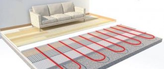
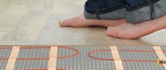
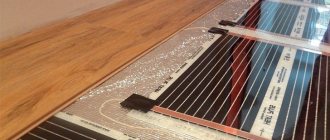
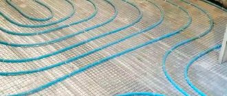
Water heated floors have significant differences from standard radiator heating. The floor pipeline, which lies in a cement screed, requires water at a certain temperature level, much lower than that circulating in the radiators. Therefore, it is necessary to install a three-mix running unit, in which the coolant will be brought to the required degree.
Bringing the liquid to the required degree of heating that meets the standards for underfloor heating (which ranges from +35 to 55 degrees) is the main function of a three-way thermomixing valve.
Design and principle of operation
A mixing valve is a device for mixing and regulating water flows; it has three openings: two inlet and one outlet. In the space between the inlet holes there is a heat-sensitive damper; it is responsible for regulating the movement of liquid - cooled and heated. Modern devices are equipped with a thermal head or control valve.
The heating floor valve operates continuously. The step-by-step process is as follows:
- heated water is supplied to the first inlet - its temperature is determined in the valve;
- if the heating degree of the water exceeds that required for heated floors, then the supply of cooled liquid from the return line opens through the second hole;
- inside the valve, heated liquid is mixed with cooled liquid;
- after obtaining the desired temperature, the return flow is closed;
- The coolant is supplied through the outlet to the underfloor heating pipes.
For the thermal valve to work effectively, it is necessary to maintain constant pressure in the line.
When operating an automatic thermo-mixing tap equipped with a servo drive, heating is carried out in 3 minutes ; if there is a thermal head, the liquid is heated in 15 minutes .
Kinds
Esbe three-way for heated floors, why is it needed.
Three-way thermal valves come in separate and mixing types. For underfloor heating, mixing valves are used.
In addition, they have different implementation methods; they can be manual or automatic. They also differ in their design - the location of the holes (inlet and outlet).
Manual
The price of a manual device is not high, but it is rarely used because it is not convenient. Suitable only for small rooms - bath, kitchen. The temperature level and volume of supplied coolant are adjusted manually using a handle.
Automatic
Automatic valves have a thermal head or an electric drive, which can be controlled by a sensor.
Types of mixing units:
- Simple - if the temperature rises, the liquid expands, the damper opens, cold and hot water mix.
- Three-way valves with a thermal head with a remote thermostat for heated floors are more advanced models. They are widely used because they are accurate and do not require electricity to operate. Average price from 500 rubles to 2500 rubles.
- Three-way valves for heating with a thermostat - they regulate the flow of heated and cooled water, and also control the temperature with a built-in thermostat. The expansion and contraction of the holes occurs automatically, depending on the temperature of the liquid.
- With an electric drive (drive with a magnet or servo drive) - the damper in the valve is activated under the influence of an electric motor, it is controlled by a controller, and a signal is received from a temperature sensor. They are easy to connect, so they are widely used. But unreliability is their main drawback, since they depend on electricity. Their cost is higher than with a thermal head, approximately 4 - 5 thousand rubles.
- With pneumatic or hydraulic drive - used more often in production, for devices with high pressure. They have a high cost, but their service life is longer.
- Electronic - adjustment is carried out by a built-in electric motor or a control element with a thermometer.
Mixing unit equipment
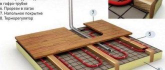
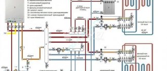
It is possible to achieve the functionality of the TP system only by having a clear understanding of the structure of the control system and the practical purpose of its main and auxiliary elements. It will be convenient to disassemble the structure and operation of a typical unit using the example of a circuit with a sequential connection of a pumping unit and a two-way thermostat valve (Fig. 3). The specified layout has a mixing unit for Valtec heated floors (Fig. 5), sold in the retail chain as a ready-made set of equipment.
Figure 3
Main functional elements of the Valtec NSU
These include:
- circulation pump;
- balancing shut-off valve (primary circuit);
- balancing valve (secondary circuit);
- bypass valve (bypass).
Pump (Fig. 3 and 5, item 3)
Initiates the supply and return of coolant through the TP units and loops. Circulation equipment similar to that used in the primary circuits of the heating system is used. The values of its main operating parameters (pressure and productivity) must be sufficient to overcome hydraulic resistance in the pipelines in order to ensure circulation of the coolant at the required speed and in specified volumes.
Balancing valve of the primary circuit (Fig. 3 and 5, item 8)
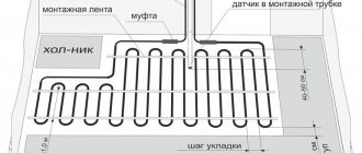
Responsible for the incoming volumes of coolant that feeds the underfloor heating system from the primary high-temperature heating circuit (T1, T2). Balancing the fluid flow is carried out by changing the valve capacity. The balancing valve is adjusted by rotating its adjusting screw with a hex key, which is closed with a protective cap. The process is also synchronized with the operation of the thermostat valve (item 1), controlled by a remote immersion sensor (item 1a). The sensor's sensitive element is mounted in a threaded sleeve (item 4).
Balancing valve of the secondary circuit (Fig. 3 and 5, item 2)
Its setting depends on the area of the heated surface of the floor covering. The opening/closing of the control device affects the change in the proportion of the ratio of the volumes of coolants from the TP return (T21) and the supply of the primary heating system (T1). Covering the return flow from the secondary circuit with a balancing valve promotes a more intensive flow of heated liquid from the heat generator (boiler). Thus, the heat output of the TP increases.
The degree of opening of the valve (Fig. 4) is set using the scale on its head (Fig. 5, item 2), where its throughput capacity is indicated in m3/hour. After completing the adjustment, the scale is secured against accidental displacement with screw 2a.
Figure 4
Bypass valve (Fig. 3 and 5, item 7)
Together with the bypass pipe (item 12), it ensures trouble-free operation of the circulation pump in the boost mode, when circulation through the TP loops stops completely or becomes insufficient. This mode can be caused by shutting off the circuits on the comb using manual valves or by the operation of their valves with simple thermostatic or automatic control. As a result, the resistance to fluid flow, as well as the load on the equipment, increases. At a certain pressure difference, the value of which is adjusted on the scale of the bypass valve (graduation in bar), it opens slightly. The coolant or part of its flow begins to flow through the bypass pipe, closing a small circulation cycle through the pump. Thus, emergency overload is eliminated and the safety of the equipment is ensured.
Auxiliary elements
Various auxiliary and service devices also help to ensure, support and control the operation of the NCS:
- thermometers – pos. 5;
- float type air vents (automatic) – pos. 9;
- drain valves – pos. 10;
- check ball valve – pos. eleven.
Figure 5
Manufacturing materials
Three-way thermomixing valves are made from the following materials:
- Brass is a copper alloy with zinc additives. The product is not subject to corrosive destruction, it is strong and durable. Sometimes these thermomixers have a chrome or nickel coating, which protects against darkening. This option is most often used in residential areas.
- Bronze is a copper alloy with tin additives. It is rare, although the quality is no worse than brass.
- Stainless steel is an excellent metal for making control products. It is characterized by durability, strength, and corrosion resistance. But the cost of appliances made from it is high, so they are not suitable for a private home.
There are titanium and carbon steel regulators, but they are recommended for industrial use. Valves are produced from silumin (an alloy of aluminum and silicon), their disadvantage is low strength.
Heating a house without a pump. Two time-tested options
Until the 90s of the last century, heating a house without a pump was the only option available, since the direction of manufacturing circulation pumps and promoting them to the masses was not developed. Thus, owners and developers of private houses were forced to install heating in their houses without a pump.
But when good boiler equipment, pipes and compact circulation pumps began to be brought to the CIS in the 90s, the situation changed dramatically. Everyone started installing heating systems. which do not work without a pump. They began to forget about gravity systems. But today the situation is changing. Developers of private houses are once again thinking about heating a house without pumps. Since interruptions and shortages of electricity, which is so necessary for the operation of the circulation pump, can be traced everywhere.
The issue of quality and quantity of electricity supply is especially acute in new buildings.
That is why today, more than ever, one proverb comes to mind: “Everything new is well-forgotten old!” This proverb is very relevant today for heating a house without a pump.
For example, previously only steel pipes, homemade boilers and open expansion tanks were used for heating. The boilers had low efficiency, steel pipes were bulky, and it was not recommended to hide them in walls.
Expansion tanks were located in attics. Because of this, there was heat loss and the threat of the roof flooding or the pipes in the tank freezing. Which in turn often led to a boiler explosion, pipe rupture and human casualties.
Today, thanks to modern boilers, pipes and other heating devices, it is possible to create a luxurious, economical heating system without a pump. Thanks to modern, efficient boilers, significant savings can be achieved.
Modern plastic or copper pipes can be easily hidden in walls. Today, home heating can also be done with both radiators and heated floors.
Today there are two main home heating systems without a pump.
The first and most common system is called Leningradka. or with horizontal spill.
The main thing in home heating systems without a pump is the slope of the pipes. Without a slope, the system will not work. Due to the slope, Leningradka is not always suitable, since the pipes run along the entire perimeter of the house. Also, due to the fact that the slope may not be enough, you have to lower the boiler below the level of your floor. In this case, the boiler is inconvenient to heat and clean.
Also, when installing a heating system at home without a Leningradka pump, doorways along the route of the pipes interfere. In this case, it is necessary to make window sills with a height of at least 900 mm.
This is necessary so that the radiator is mounted and there is enough height for the pipes along the slope. Otherwise, the system is quite functional, namely with cast iron, steel and aluminum radiators.
The second home heating system without a pump is called a "Spider" or vertical top-spout system.
Today this is the most reliable and practical home heating system without a pump. The main thing is that the “Spider” system is devoid of all the disadvantages of the “Leningradka”, with the exception of the slope of the return line, due to which the boiler also has to be lowered below the floor.
Otherwise, the Spider system is the most efficient system. You can attach any radiators and heated floors to the Spider system. You can mount valves under the thermal head on radiators in the “Spider” system and hide pipes in the walls, and so on.
Today, it is increasingly necessary to recommend the “Spider” system to developers, because... Today this is the ideal home heating system without a pump.
Thank you for reading this article!
Advantages and disadvantages
Three-way thermostatic mixing valves are simple in design, yet reliable and durable. Their use allows for high-quality and precise control of the floor heating level.
Thermostatic valve for heated floors: types and their design, how to choose, installation diagrams and alternative connection methods
The devices are sealed and compact. Plus - they do not allow the pipes and screed to overheat, which extends the life of the system.
The benefits of control valves are irrefutable, but they have a number of disadvantages:
- They increase hydraulic resistance - this negatively affects the functioning of a unit that has more than one collector.
- There is a risk of a large volume of hot coolant entering the floor pipes. And this can lead to leakage and airing of the system. Such problems most often occur when the device is starting up.
Pipe laying methods
Along the perimeter of the house, highways in such a system, both on the first and second floors, are usually carried out under the floor. Such a “hidden” system does not spoil the appearance of the premises. However, it should be taken into account that with such an installation, most likely, you will have to use the bottom method of connecting radiators. And with this insertion method, unfortunately, the batteries do not work at full capacity. The solution may be to use a bypass of a special design.
In this case, a metal-plastic piece of length equal to the height of the battery is cut into the “supply” pipe in front of the radiator. Connection to the main line is made through it, at the top of the section. A short vertical section is welded to the “return” pipe. The radiator is connected to it at the lower point of the opposite section.
Manufacturers
Preference should be given to mixing valves from manufacturers that have proven themselves well in the market. Such companies include:
- Esbe (Sweden) - occupies a leading position in the quality of products of this type. The valves are reliable, with a warranty period of more than 5 years.
- Valtec is a Russian-Italian company; its mixing taps have good characteristics at an affordable price. Warranty - 7 years.
- Honeywell (America) - the priority of mixers from this company is considered to be convenient and uncomplicated installation. They are reliable, but expensive.
However, it should be remembered that even high-quality products if installed incorrectly will not ensure correct operation of the system.
How to choose?
It is recommended to select a three-way valve in specialized stores. When choosing a model, you need to take into account its characteristics. When purchasing a device you need:
- study all documentation - warranty, manufacturer’s certificate, installation and operating instructions;
- give preference to bronze or brass devices - they will not expand when heated;
- based on the valve capacity - this parameter must correspond to the boiler performance;
- select a valve with a cross-section that exactly matches the size of the floor pipes; if there is a mismatch, you will have to buy adapters.
An important point is that even the apparent coincidence of the diameters of the valve inlet and outlet does not indicate the throughput level. This is affected by the size of the internal cross-section of the holes. This parameter is specified in the accompanying documents.
You need to choose a device based on the size of the heated room - for large areas an automatic device is recommended; it is able to maintain heating at the proper level. For small rooms, a simple one with a thermal head will do the job, so there is no point in overpaying for a more complex model.
When purchasing, you must visually inspect the device for chips and cracks. If the device is brass, then the inside should be golden.
Purchasing automatic devices will facilitate the adjustment process. And the presence of software will allow you to adjust the temperature taking into account the time and day of the week.
Heated floor diagram with a three-way valve
A three-way valve can be installed together with a mixing and distribution unit, or as a separate device.
Three-way valve. We install it correctly.
Scheme with separately installed valve
If the valve is mounted separately, it takes over all the functions of the manifold. This scheme is intended for small rooms, no more than 25 m2. The temperature level is adjusted using a special device and a thermostat, they are located in the valve.
The disadvantage of using a valve according to this scheme is that there is no way to dose the flows.
The system looks like this:
- a three-way valve is installed on the hot coolant supply pipe;
- a temperature sensor is attached behind it;
- Next, a circulation pump is installed; it will deliver water with the required heating degree to the sex pipeline.
Scheme without mixing unit
Valve with mixing unit
If the area is large, then it is necessary to use a scheme where the valve is part of the distribution unit.
It will ensure uninterrupted operation of the floor heating device, and the water entering the floor line will be at the required temperature and volume.
The connection diagram is as follows:
- a pump is installed on the supply pipe; it will pump the heated coolant from the source;
- then a temperature sensor is installed, it will control the degree of heating;
- at the next stage, a three-way valve is attached - it mixes the coolant to a given degree;
- a tap is placed on the return circuit through which cooled water will flow into the three-way device.
Scheme with a mixing unit
That is, coolant heated to the required temperature will be supplied to the underfloor heating pipes.
Connection diagrams depending on design
In addition, the connection diagrams differ in the design and direction of the coolant in the device, there are:
- L-shaped - the product is equipped with two holes on the side and one round hole on the bottom of the body. The heated liquid is supplied to the side inlet, and the cooled liquid is supplied to the bottom. After mixing, the water moves into the floor branches through another side hole.
- T-shaped - both flows, cold and hot, enter the mixer through the side inlets. The mixed coolant is sent to the floor through the central lower outlet.
When deciding on a diagram for installing a three-position valve, you should consider how it will fit into the pipeline piping.
Varieties
Existing types of valves are capable of working with boiler equipment from leading foreign (Vaillant, Baxi, Ariston, Navien, Viessmann) and domestic (Nevalux) manufacturers using gas, liquid and solid fuels in situations where automatic control of the system operation due to the type of fuel is difficult or broken when the automation fails. Depending on their design and operating principle, safety valves are divided into the following groups:
- According to the purpose of the equipment in which they are installed:
- For heating boilers that have the above design, they are often supplied on fittings in the form of a tee, into which a pressure gauge is additionally installed to check the pressure and a venting valve.
- For hot water boilers, the design includes a flag for draining water.
- Tanks and pressure vessels.
- Pressure pipelines.
- According to the operating principle of the clamping mechanism:
- From a spring, the clamping force of which is regulated by an external or internal nut (its operation is discussed above).
- Lever-load type, used in industrial heating systems designed to discharge large volumes of water; their response threshold can be adjusted by hanging weights. They are suspended on a handle connected to the shut-off valve using a lever principle.
- Locking mechanism speeds:
- Proportional (low-lift spring) - the sealed lock rises in proportion to the pressure and is linearly related to its increase, while the drain hole gradually opens and closes in the same way with a decrease in the volume of coolant. The advantage of the design is the absence of water hammer under various modes of movement of the shut-off valve.
- Two-position (full-lift lever-load) - operate in open-closed positions. When the pressure exceeds the response threshold, the outlet hole opens completely and the excess coolant volume is released. After the pressure in the system is normalized, the outlet is completely blocked; the main drawback of the design is the presence of water hammer.
- By adjustment:
- Non-adjustable (with caps of different colors).
- Adjustable screw parts.
- According to the design of the spring compression adjusting elements:
- An internal washer, the operating principle of which was discussed above.
- External screw, nut, models are used in domestic and communal heating systems with large volumes of coolant.
- Using a handle, a similar adjustment system is used in flanged industrial valves; when the handle is fully raised, it is possible to perform a one-time release of water.
Installation and connection of a three-way valve to a warm floor
Connecting a three-way valve to a warm floor is not difficult; you can do it yourself. The main thing is to follow the steps according to the attached instructions.
All inputs and outputs are indicated by letters:
- A - input for heated coolant;
- C - inlet for chilled water;
- AB is the outlet.
Before connecting the device, it should be taken into account that it may need to be dismantled, so it is necessary to have an unobstructed approach to the unit.
Materials and tools
Before installing the valve, you need to stock up on the necessary tools. You will need wrenches (2 pcs), pliers, American nuts with union-type gaskets, FUM tape.
Work progress
Connecting a heated floor to the heating system. Three-way mixing valve.
First of all, the three-way valve must be checked for functionality.
To do this, the minimum value is set on the regulator, then hot water is released through the valve. If the device is functioning correctly, the damper should close immediately.
Installation of the tap must be done together with the installation of the manifold group and before pouring the screed.
When using any scheme, the valve is installed using American union nuts.
The work looks like this:
- The fittings located at the ends of the pipes are cleaned of dirt and burrs.
- The same procedure is done with the valve pipes.
- The nut is checked for gaskets.
- Then screw the nuts onto the pipes and tighten them - but not too much. This procedure involves two wrenches - one for tightening the nut, the second for holding the valve.
- A mechanical filter is installed in front of the valve.
It is necessary to monitor the correct connection of the valve outputs: to A - hot water, to B the bypass coming from the return line, to AB the manifold with floor outlets.
To ensure the tightness of the joints, it is recommended to screw plumber's tape or FUM tape.
System check
In addition to the correct installation of the mixing tap, its operation must be checked. System testing is carried out with the coolant heated to 25 degrees. The time for crimping is 24 hours.
After checking, you can proceed to pouring the screed.
Joint connection of two boilers
To increase the heating comfort of a private home, many owners install two or more heat sources that run on different energy sources. At the moment, the most relevant combinations of boilers are:
- natural gas and wood;
- solid fuel and electricity.
Accordingly, the gas and solid fuel boiler must be connected in such a way that the second automatically replaces the first after burning the next portion of firewood. The same requirements are put forward for connecting an electric boiler to a wood boiler. This is quite simple to do when a buffer tank is involved in the piping scheme, since it simultaneously plays the role of a hydraulic arrow, as shown in the figure.
As you can see, thanks to the presence of an intermediate storage tank, 2 different boilers can serve several heating distribution circuits at once - radiators and heated floors, and in addition load an indirect heating boiler. But not everyone installs a heat accumulator with a TT boiler, since this is not a cheap pleasure. In this case, there is a simple diagram, and you can install it yourself:
Note. The scheme is valid for both electric and gas heat generators operating together with solid fuel.
Here the main source of heat is a wood heater. After a stack of firewood burns out, the air temperature in the house begins to drop, which is registered by the room thermostat sensor and immediately turns on heating by the electric boiler. Without a new load of firewood, the temperature in the supply pipe decreases and the overhead mechanical thermostat turns off the pump of the solid fuel unit. If you ignite it after some time, everything will happen in the reverse order. This video is described in detail about this joint connection method:
Tying using the method of primary and secondary rings
There is another way to combine a solid fuel boiler with an electric one to supply a large number of consumers. This is a method of primary and secondary circulation rings, which provides for hydraulic separation of flows, but without the use of a hydraulic needle. Also, for reliable operation of the system, a minimum of electronics is required, and a controller is not needed at all, despite the apparent complexity of the circuit:
The trick is that all consumers and boilers are connected to one primary circulation ring by both the supply and return pipelines. Due to the small distance between connections (up to 300 mm), the pressure drop is minimal compared to the pressure of the main circuit pump. Due to this, the movement of water in the primary ring does not depend on the operation of the secondary ring pumps. Only the temperature of the coolant changes.
Theoretically, any number of heat sources and secondary rings can be included in the main circuit. The main thing is to choose the right pipe diameters and the performance of the pumping units. The actual performance of the main ring pump must exceed the flow rate in the most “gluttonous” secondary circuit.
To achieve this, it is necessary to perform a hydraulic calculation and only then will it be possible to select the right pumps, so an ordinary homeowner cannot do without the help of specialists. In addition, it is necessary to link the operation of solid fuel and electric boilers by installing shut-off thermostats, as described in the following video:
Common installation mistakes
The most common mistake when installing a three-way valve is that the supply and return floor circuits are incorrectly connected. For example, when floor contour pipes are connected to the inlet.
Therefore, care is required; for this, there are letter designations at the mixer outputs. If you mix up the holes, the device will not function.
In addition, it is necessary to strictly follow the manufacturer's instructions regarding the distance between straight sections before and after the screw. If this rule is violated, the functioning of the regulator will be disrupted.
Rules for installing fittings
Typically, the manufacturer indicates the movement of water flow with arrows on the body of a three-way valve. Using these guidelines, you can determine the type of valve. Connection to the system occurs as indicated by the arrows. The installation location should be convenient for subsequent adjustments or replacement in case of malfunction. Both return and supply are suitable for this. But read the instructions carefully, since not all valves can be installed for supply.
Since most of the valves inside are made of ceramic, they do not handle dirty water well. Therefore, it is better to install a filter in front of the valve. If this is not done, the device may become clogged. In some cases, it is enough to clean it, but sometimes even this does not save. Therefore, you should not skimp on filters.
The electric drive should not be located at the bottom, and mechanical thermostatic mixers are also not recommended to be installed this way, only vertically. But I can say from my own experience that in some cases this is possible. And reviews from some owners confirm this.
Features of operation
When operating a heated floor mixing valve, there are special points. The main one is the mandatory installation of a filter. In addition, it is not recommended to place a mixer with a thermal head in a manifold group that serves more than one room or is located in an adjacent room. A device with a remote temperature sensor placed in a heated room is suitable.
The mixing valve is the main element in the water heated floor system. The quality of room heating depends on how correctly it works. Therefore, its selection and installation must be approached responsibly. If you are not confident in your abilities, then it is better to invite a professional.
Useful tips
Before starting the heating system, you must make sure that the three-way valve and other components are in full working order, do not need repair or replacement, and also meet operational requirements. It is not recommended to install a tee on a pipeline with a pipe diameter of 40 millimeters or more. When operating in a hot environment, the valve must be opened with extreme caution, otherwise there is a risk of hydraulic valve failure.
The best material for a three-way valve is brass.
Experts recommend placing control devices or a turning handle with a rod so that they are freely accessible. When choosing a suitable faucet model, it is advisable to give preference to products made of brass. They are characterized by a long service life and resistance to all kinds of influences.
As for the control method, the best option would be a product with pneumatic control. Before making a choice and buying a tee, it is better to consult with a specialist, talk about the possible pros and cons of the available models, and also read reviews about them on thematic forums.