For individual water supply, borehole and well sources of clean water are used, the intake of which is carried out using submersible or surface electric pumps. They cannot operate continuously and must be turned off as the main line fills; the cycles of turning on and off the electric pump are controlled by automation for the well or well.
When organizing a water supply system for a private home, an electric pump is selected based on flow rate, after which an automatic control system for its operation is installed, including electronics and a storage tank. The efficiency of water supply, the service life of the electric pump and the ease of use of the water supply depend on the correct selection and configuration of electronic control devices.
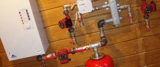
Fig. 1 Example of water supply arrangement
Accumulator pressure
Understanding how a hydraulic accumulator works will help you better cope with self-tuning of control equipment.
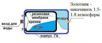
There are two types of hydraulic tanks: with a rubber insert resembling a pear, or with a rubber membrane. This element divides the container into two non-communicating parts, one of which contains water, and the other contains air.
Inside the hydraulic tank there is a rubber pear-shaped insert or rubber membrane. The pressure in the hydraulic tank can be adjusted by pumping or bleeding air
In any case, they work approximately the same. Water enters the tank, and a rubber insert presses on it to ensure the movement of water through the plumbing system.
Therefore, there is always a certain pressure in the hydraulic tank, which changes noticeably depending on the amount of water and air in the tank.
In order to measure the air pressure in the hydraulic tank before setting the relay, you should connect a pressure gauge to the nipple connection provided on the device body
There is usually a car nipple on the tank body. Through it, you can pump air into the hydraulic tank or bleed it to adjust the operating pressure inside the tank.
When connecting the pressure switch to the pump, it is recommended to measure the current pressure in the hydraulic tank. The manufacturer sets the default value to 1.5 bar. But in practice, some of the air usually escapes, and the pressure in the container will be lower.
To measure the pressure in the accumulator, use a regular car pressure gauge. It is recommended to choose a model with a scale with the smallest gradation step. Such a device will allow for more accurate measurements. It makes no sense to measure pressure if it is not possible to take into account one tenth of a bar.
In this regard, it makes sense to check the pressure gauge that is equipped with an industrial pumping station.
Manufacturers often save money and install inexpensive models. The accuracy of measurements using such a device may be questionable. It is better to replace it with a more reliable and accurate device.
When choosing a pressure gauge for a pumping station or a pump with a hydraulic tank, you should pay attention to mechanical models with an accurate gradation scale
Mechanical car pressure gauges do not look very presentable, however, judging by the reviews, they are much better than newfangled electronic devices. If, nevertheless, the choice is made in favor of an electronic pressure gauge, you should not save. It is better to take a device made by a reliable manufacturer than a cheap plastic craft that does not provide accurate data and can break at any time.
Another important point is that the electronic pressure gauge requires power supply, you will have to monitor this. Checking the pressure in the hydraulic tank is very simple.
The pressure gauge is connected to the nipple and the readings are taken. Normal pressure is considered to be between one and one and a half atmospheres. If the pressure in the hydraulic tank is too high, the water supply in it will be less, but the pressure will be just fine.
This diagram clearly shows the procedure for connecting a pressure switch and pressure gauge to a submersible pump and hydraulic tank in order to automate the operation of pumping equipment
It should be remembered that too high pressure in the system can be dangerous. In this case, all components of the water supply system constantly work under increased load, and this leads to rapid wear of the equipment. In addition, in order to maintain increased pressure in the system, you have to pump water into the tank more often, and therefore turn on the pump more often.
This is also not very useful as it increases the likelihood of breakdowns. When setting up a system, a certain balance is required. For example, if the pressure in the accumulator is too high or too low, it can damage the rubber gasket.
The addition of a pressure switch with a five-way fitting and a pressure gauge transforms the device into the category of automation units
The union nut makes it much easier to connect the device in hard-to-reach places
The design uses a five-way fitting that connects to the relay and has 3 more threaded outputs
Briefly about the main thing
Automation for wells is needed if frequent switching on and off of the pumping station is required, as well as to maintain constant pressure in the system.
There are three generations of automation for pump control.
The first generation of automation is most often mechanical, which is why it has a low cost.
The second generation has an electronic control system, due to which water is supplied autonomously.
The most reliable automatic water supply control systems are of the third generation, since they are equipped with an electronic control unit with a frequency converter. It extends the service life and also reduces electricity consumption.
Ratings 0
Operating principle and existing types of automation
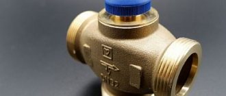
Water pressure switch for pump
There is no point in buying automation for surface pumps used only for watering the garden. You can turn it on yourself for a certain time and then turn it off. But connecting a well pump to the water supply system of the entire house cannot be done without a smart device. When giving preference to one or another automation model, you must first find out what protection system is already installed in the pump by the manufacturer. Typically, modern units are already equipped with protection against overheating and dry running. Sometimes a float is included in the package. Based on these data, we begin to select automation for the pump, which is presented to the consumer in 3 options.
The simplest automation of the 1st generation
This protection is most often used for automated water supply. Automation consists of 3 devices:
- The dry run blocker will turn off a running unit without water, protecting it from overheating. Sometimes you can additionally install a float switch. It plays the same role, turning off the pump when the water level drops, preventing it from overheating during dry running. At first glance, the devices are primitive, but they protect the engine effectively.
- The hydraulic accumulator is an integral part of the 1st generation automation. Sometimes this is inconvenient, but without it you won’t be able to automate the water supply. The automatic hydraulic accumulator of a submersible pump works as a water storage tank. Inside there is a working mechanism - a membrane.
- The relay monitors the water pressure in the accumulator. A pressure gauge must be installed on it, allowing you to configure the parameters for the operation of the relay contacts.
It is easiest to install any pump with 1st generation automation, since there is no complex electrical circuit. The system works simply. When water flow begins, the pressure in the accumulator decreases. Having reached the lower limit, the relay turns on the pump to pump a new portion of water into the tank. When the pressure in the accumulator reaches the upper limit, the relay turns off the unit. During operation, the cycle repeats. The minimum and maximum pressure in the accumulator is regulated using a relay. The device sets the lower and upper response limits, and a pressure gauge helps with this.
Electronic automation 2nd generation
The 2nd generation automatic control device is an electronic unit with a set of sensors. The latter are located on the pump itself, as well as inside the pipeline, and allow the system to operate without a hydraulic accumulator. The signal from the sensors is received by the electronic unit, where the operation of the system is controlled.
How an installed sensor can replace a hydraulic accumulator can be understood by the operation of the system. Water accumulation occurs only in the pipeline where one of the sensors is installed. When the pressure decreases, the sensor sends a signal to the control unit, which, in turn, turns on the pump. After the water pressure in the pipeline is restored, a signal to turn off the unit is sent according to the same scheme.
To install such automation you will need basic knowledge of electrical engineering. The operating principle of 1st and 2nd generation protection is almost the same - based on water pressure. However, an electronic unit with sensors is much more expensive, which does not make it popular among users. Automation also allows you to refuse to use a hydraulic accumulator, although it often helps out during a power outage. There is always a supply of water left in the container.
Advanced electronic automation 3rd generation
The most reliable and efficient is the 3rd generation automation. Its cost is quite high, but it saves significant energy thanks to precise tuning of the engine operation. It is better to entrust the connection of such an automatic unit to a specialist. The 3rd generation automation 100% protects the engine from all kinds of breakdowns: overheating from dry running, combustion of windings due to voltage drop, etc.
As in the 2nd generation analogue, the automation operates from sensors without a hydraulic accumulator. But the essence of its effective work lies in fine settings. The fact is that any pump electric motor, when turned on, pumps water at full power, which is not always required when its flow rate is low. The 3rd generation automation switches on the engine at the power required for a certain amount of water intake and flow. This saves energy and extends the service life of the unit.
Video description
This video shows how to correctly configure a pressure switch:
You should install automation only if it is necessary. For example, for an autonomous heating system. To water the site in the summer seasons, automation is not needed. A simple pump will suffice for this. A pump that has a performance higher than the well's flow rate (return) will supply water in jerks, which can lead to breakdown.
The automation control unit should be placed in a dry place so that the contacts inside the system do not oxidize and a short circuit occurs. Also, the place should be easily accessible, since in the event of a breakdown or when changing settings, it will be inconvenient to approach the unit if it is blocked.
Periodic maintenance of the automation unit (adjustment, performance testing, replacement of parts) should be carried out. This is required because if the motor does not operate correctly and is not turned on in a timely manner, the contacts in the pump burn out and it stops working.
Automation unit service Source mhs-perm.ru
Installation of electronic automation should only be carried out if you have experience. If it is not there, then it is better to contact specialists, since an incorrectly installed system will quickly fail or not start working at all.
If an external pump is used, which is connected to a well, then a storage tank (if there is none) and a pressure regulator should be installed for it. There are external pumps that come complete with these modules or are initially connected to its housing. You should also install a fluid flow relay in the form of electrolytic sensors. This will prevent air from entering the motor.
Expensive systems are best installed if frequent use of water in different volumes is required, since they will be able to regulate its flow.
Well automation control unit Source aspekt-ekb.ru
Setting up the pressure switch
Water pressure switch for pump
During the assembly of the pumping station, special attention is paid to setting the pressure switch. The ease of operation of the water supply system, as well as the trouble-free service life of all components of the device, depend on how correctly its maximum levels are set.
At the first stage, you need to check the pressure that was created in the tank during the manufacture of the pumping station. Typically, at the factory, the switch-on level is set at 1.5 atmospheres, and the switch-off level is 2.5 atmospheres. They check this with an empty tank and the pumping station disconnected from the power supply. It is recommended to check with an automotive mechanical pressure gauge. It is housed in a metal case, so the measurements are more accurate than using electronic or plastic pressure gauges. Their readings can be affected by both the room temperature and the battery charge level. It is desirable that the pressure gauge scale limit be as small as possible. Because on a scale of, for example, 50 atmospheres, it will be very difficult to accurately measure one atmosphere.
To check the pressure in the tank, you need to unscrew the cap that closes the spool, connect the pressure gauge and take a reading on its scale. The air pressure should continue to be checked periodically, for example once a month. In this case, the water must be completely removed from the tank by turning off the pump and opening all taps.
Another option is to carefully monitor the pump shut-off pressure. If it increases, this will mean a decrease in air pressure in the tank. The lower the air pressure, the greater the supply of water can be created. However, the pressure spread from a completely filled to an almost empty tank is large, and all this will depend on the preferences of the consumer.
Having chosen the desired operating mode, you need to set it by bleeding off excess air, or pump it up additionally. It must be borne in mind that the pressure should not be reduced to less than one atmosphere, nor should it be over-pumped. Due to the small amount of air, the rubber container filled with water inside the tank will touch its walls and be wiped. And excess air will not make it possible to pump in a lot of water, since a significant part of the tank’s volume will be occupied by air.
Conclusions and useful video on the topic
The following material very clearly shows how to properly disassemble a water jet pump, as well as the process of reassembling one of the models:
Disassembling and repairing Vodomet pumps requires attention to detail and some skill. Over time, the task becomes quite feasible and familiar. Many DIYers service and repair these pumps with complete success.
Have questions about the topic of the article, found inaccuracies, or have information that you would like to share with visitors to our site? Please leave your comments in the block below.
Hydraulic accumulator device, principles of operation
Setting the accumulator pressure switch
To better understand the functions of individual elements, it is necessary to consider the system as a whole.
From a well or other source, water is pumped into the main pipeline. To prevent it from moving in the opposite direction, a safety valve is installed. Shut-off valves are installed in the required places. It is used for preventive maintenance, adjustments, and replacement of failed units.
Water flows through the pipeline into a special container, which performs several functions:
The main working element of such a container is a flexible partition. But the initial pressure in the tank itself is created by the pump. With appropriate equipment, it is controlled from a special remote control. Data is received there from the pressure switch for the hydraulic accumulator.
Above is part of a smart home class diagram. It connects to the general control system. In practice, more economical solutions are often used.
To successfully solve the identified problems, the following designs of hydraulic accumulators are used:
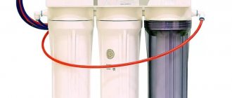
This picture shows another important element, the flow filter. It prevents the entry of mechanical contaminants, damage to the relay and blocking of its drive mechanisms. The increased tank capacity is useful not only for high daily consumption. It will reduce the number of pump starts/stops, which will have a positive impact on the durability and reliability of the system.
The standard method for calculating tank volume (VT) uses the following formula:
OB=16.5 x RV/KV x CD x 1/DVK, where:
In order not to embarrass oneself when living year-round, a tank with a capacity of 40-60 liters is sufficient for a family of three. Similar advice is given by specialized experts. In fact, it is better to make a more accurate calculation using the above method. The results obtained should be increased taking into account guest visits and other situations accompanied by increased water consumption. This approach will help you purchase a hydraulic accumulator for water supply, the price of which will correspond to the technical characteristics and needs of future users.
When placing the tank at the highest point of the structure, the force of gravity will be used. But we must take into account that the room must be reliably protected from adverse external influences. It maintains temperatures above 0°C all year round.
It is necessary to remember about the increase in mechanical loads. A large water tank weighs a lot, so sometimes additional reinforcement of the structure’s load-bearing frame is required. For these reasons, large containers are often installed in the basement.
How to install a pressure switch for a hydraulic accumulator
Before performing work operations, it is necessary to clarify the general requirements. In order for the water supply system to function optimally, the pressure difference for turning the pump on and off is set within the range from 0.9 to 1.8 atm. Exceeding it will increase energy consumption.
To calculate what pressure should be in the hydraulic accumulator (DHA), use the formula DHA = (B+6.5)/10, where:
The process of connecting a pressure switch to a hydraulic accumulator
For study, this article discusses a mechanical pressure switch for a hydraulic accumulator. This design is repeated in modifications by different manufacturers, with relatively minor changes.
This product is connected to the water supply system in assembled form. Flexible tubing designed for appropriate pressure levels can be used to place it in a convenient location. If necessary, use transition fittings. Upon completion of installation, the tightness of the threaded connections is checked experimentally.
The electrical connection can be made directly to the pump power supply circuit. Use wires designed for appropriate power. To eliminate errors, it is recommended to use products with color braiding. The “earth” standard is a combination of yellow and green. The electric motor is connected to a 220 V network through an automatic device, which ensures quick shutdown in the event of a short circuit.
All electrical installation work is carried out with the voltage turned off. It is necessary to exclude accidental supply of voltage during the process of adjusting the pressure switch for the hydraulic accumulator.
How to disassemble the pump?
The design of the Vodomet pump cannot be called completely simple and understandable. Before starting disassembly, it is recommended to familiarize yourself with the features of its design in as much detail as possible. It doesn’t hurt to record the correct position of each element: write it down, photograph it, shoot it on video, etc.
You should also pay attention to the correct position of each part in relation to the concepts of “top” and “bottom”. If the wheels were installed incorrectly after repair, the pump will still work, but not very efficiently.
Problems may also arise after rewinding the motor. Not all pump owners remember the correct location of the contacts.
To carefully remove the cover of the Vodomet pump, you can use the so-called oil filter puller or its soft analogue - twisting their fabric (rope) with a lever
Before disassembling, the pump, of course, should be disconnected from the power supply and removed from the well. To make the work easier, it is better to disconnect the water supply pipe from the pipe and remove the metal cable.
When the pump is in operating position, its washed motor is in the upper part, and the pumping part, consisting of impeller wheels and cups with lids, is in the lower part. But when disassembling the pump, it is more convenient to hold it “upside down”, i.e. engine down.
The first step in disassembling the pump is to unscrew the bottom cover. This operation is performed using a sufficiently long screwdriver threaded through the eyelets for hanging the cable. You need to unscrew it counterclockwise.
It may be more convenient to use other devices, for example, gas wrench number three. A device for removing the oil filter cover, well known to motorists, or its equivalent made from a strip of durable fabric with a lever for twisting it, is also suitable.
After this, you need to carefully remove the chambers with lids and impeller wheels from the pump housing. The lids of the glasses are numbered from 1 to 3. Usually all the glasses with the number “1” are put on the shaft first, then with the number “2”, then with the number “3”.
When disassembling the water jet pump, these elements will be removed in the reverse order. It is better to write down the numbering order of the glasses to avoid mistakes during assembly.
This photo shows the pump part of the device disassembled. The elements are laid out in the order in which they were assembled. You should immediately remember which side is the top (click to enlarge)
It wouldn’t hurt to immediately clarify the direction of movement of the shaft. To do this, the pump with the wheels removed is simply turned on for a few seconds. The wheel should be positioned in such a way that water is sucked in from the bottom center, and water flows upward to the outer part of the ring.
In the correct position, the ring with the blades should be installed with the wide part towards the engine, i.e. protrusion down and smooth side up.
This is what the Vodomet pump motor looks like when removed from the device body. The shaft is secured with two clips that need to be held with pliers to remove it.
The pump shaft is not twisted, as in similar models, but is fixed with two clips. If it needs to be removed, tighten the clips with pliers and remove the shaft. When the cups with impellers are removed, it may be necessary to also remove the electric motor. This will require some effort, since it is pressed into the body quite tightly.
To avoid bending the shaft, place the pump housing on a support with a hole into which the shaft can be inserted. After this, you should carefully knock the engine out of the housing using a hammer and a piece of wood. They hit the end with a hammer, and the board acts as a shock absorber.
When the position of the motor in the housing changes, you must first remove the ring-shaped retaining gasket. It needs to be rotated 90 degrees inside the case, squeezed a little and removed so as not to damage it on the internal threads of the case. You can immediately pay attention to the position of this gasket.
The photo shows the elements of a disassembled Vodomet pump engine: 1 – hydraulic part shaft; 2 – oil seal spring, 3 – oil seal, 4 – front cover; 5 – membrane; 6 – front flange; 7 – rotor
It should be facing the engine with the side from which the chamfer is removed. After this, you can remove the engine from the housing. It is closed by the top cover of the pump, which is secured with two strong sealing rubber bands.
To remove the cover, you need to lay the engine on its side. Then the cover is carefully knocked out of the engine housing by hitting it with a wide screwdriver and a rubber mallet. You can use other suitable tools for this. There is a capacitor under the cover. Sometimes this element fails, but it is not difficult to replace.
Be careful when handling the pump housing. Sometimes it becomes necessary to fix the device in a vice. First, it is recommended to wrap the body at the fixation site with shock-absorbing material. The force should be moderate so as not to deform the product.
Image gallery
Photo from
Common pump problem
Assembly of the mechanical part of the pump
Fastening the stationary glass with a washer
Location of parts during assembly
Cost of relays and hydraulic accumulators of some manufacturers
Relay models can be purchased relatively inexpensively. Usually the cost of products does not exceed one thousand rubles. However, electronic analogues may have a higher price, as they allow for more precise adjustments. The table shows models of some manufacturers and their prices.
| Image | Model | Dimensions in millimeters | Price in rubles |
| Gilex RDM-5 | 110x110x70 | 900 | |
| Danfoss KP1 | 107x65x105 | 1 570 | |
| Belamos PS-7 | 150x80x150 | 575 | |
| Caliber RD-5 | 103x65x120 | 490 |
Related article:
As for hydraulic accumulators, their cost can be noticeably higher. It mainly depends on the volume of the structure. A large tank can significantly reduce the number of work cycles. However, there is not always enough space for it. The table shows prices for hydraulic accumulators for water supply of different sizes.
| Manufacturer | Volume in liters | Cost in rubles |
| Gilex | 24 | 1 400 |
| 50 | 3 500 | |
| 100 | 6 300 | |
| Poplar | 24 | 1 100 |
| 50 | 2 900 | |
| 100 | 5 100 |
Decoding the markings of various models
Marking of water pump models Vodomet.
Pumping mechanisms are available in several modifications; you can choose a unit with characteristics suitable for both domestic needs and industrial purposes. Design features are reflected in the markings of the models.
Example of designation: “Water cannon” 55/35, where
- "Water cannon" - serial name;
- the number 55 indicates the maximum water flow, indicated in l/min;
- 35 - highest pressure.
The marking may contain additional letter designations:
- “A” - the pump is equipped with a float switch;
- “BK” - a unit with a 1 m long cable without an electrical plug;
- "PROF" - pump without an automatic shut-off mechanism;
- “M” - main unit;
- “HOUSE” - for automatic water supply systems in private homes;
- “Ch” - automatic control mechanism;
- “DF” - with a bottom filter.
What should be the pressure in the accumulator?
One part of the accumulator contains compressed air, and water is pumped into the second. The air in the tank is under pressure - factory settings - 1.5 atm. This pressure does not depend on the volume - it is the same on a tank with a capacity of 24 liters and 150 liters. The maximum permissible maximum pressure may be more or less, but it does not depend on the volume, but on the membrane and is indicated in the technical specifications.
Accumulator design (image of flanges)
Preliminary check and pressure correction
Before connecting the accumulator to the system, it is advisable to check the pressure in it. The settings of the pressure switch depend on this indicator, and during transportation and storage the pressure could drop, so monitoring is very desirable. You can control the pressure in the hover tank using a pressure gauge connected to a special input in the upper part of the tank (capacity of 100 liters or more) or installed in its lower part as one of the piping parts. Temporarily, for control, you can connect a car pressure gauge. Its error is usually small and it is convenient to work with. If this is not the case, you can use the standard one for water pipes, but they are usually not very accurate.
Connect the pressure gauge to the nipple
If necessary, the pressure in the accumulator can be increased or decreased. There is a nipple at the top of the tank for this purpose. A car or bicycle pump is connected through the nipple and the pressure is increased if necessary. If it needs to be vented, the nipple valve is bent with some thin object, releasing the air.
What air pressure should be
So should the pressure in the accumulator be the same? For normal operation of household appliances, a pressure of 1.4-2.8 atm is required. To prevent the tank membrane from tearing, the pressure in the system should be slightly higher than the pressure of the tank - by 0.1-0.2 atm. If the pressure in the tank is 1.5 atm, then the pressure in the system should not be lower than 1.6 atm. This value is set on the water pressure switch, which works in tandem with the hydraulic accumulator. These are the optimal settings for a small one-story house.
If the house is two-story, you will have to increase the pressure. There is a formula for calculating the pressure in the hydraulic tank:
Vatm.=(Hmax+6)/10
Where Hmax is the height of the highest point of water intake. Most often this is a shower. You measure (calculate) at what height relative to the hydraulic accumulator its watering can is located, substitute it into the formula, and get the pressure that should be in the tank.
Connecting a hydraulic accumulator to a surface pump
If the house has a jacuzzi, everything is more complicated. You will have to select it empirically - changing the relay settings and observing the operation of water points and household appliances. But at the same time, the operating pressure should not be greater than the maximum permissible for other household appliances and plumbing fixtures (indicated in the technical specifications).
Video description
This video shows how to properly install the automation:
The length of the pipe should be sufficient to immerse it in water at least 1 m so that air cannot enter the system, as this may cause the motor to burn out. Before starting the system, you should fill it with water to squeeze out the air. If the automation for the pump with a hydraulic accumulator has been installed correctly, then after activating the power, the water supply will begin.
Connected external pump with automation and hydraulic accumulator Source kanaliza.ru
Purpose of the pump control cabinet
Connecting the pump to the automation is not complete without installing an electrical cabinet. It is especially important in a water supply system powered by a submersible unit. All control, monitoring and fuses are located inside the cabinet.
The automatic machines installed in the cabinet perform a smooth start of the engine. Easy access to the equipment allows you to adjust the frequency converter, measure current characteristics at the terminals, and adjust the rotation speed of the pump shaft. If several wells with pumps are used, all control devices can be placed in one cabinet. The photo shows a typical diagram of equipment that may be located in a cabinet.
The video talks about pump control:
Video description
This video shows an analysis of individual parts of the automation and their properties:
In the third generation system, surge protection devices are installed in the network, which prevent the combustion of electronic elements inside the control unit, as well as its restart after a surge.
Also, for such systems, a control cabinet is installed, which is similar to an electrical distribution panel. For submersible pumps, it is more important than for external ones, since it can be used to adjust the operation of the device, but getting to the submersible pump is problematic.
Inside such a cabinet there are fuses and all control elements, for example, a smooth motor start and a frequency converter regulator. Also inside are current sensors and a motor shaft speed controller. It is recommended to install third-level systems with a control cabinet if you need to connect several wells to each other.
Submersible pump control system (electrical cabinet) Source www.owen.ru
Criteria for selecting a relay for a pump
There are many universal models that are sold separately from pumping stations and can be used to assemble a system with your own hands. When purchasing a relay or automation unit, you must rely on the characteristics of the device. They can be found in the technical documentation.
It is important that the relay’s capabilities match the characteristics of the rest of the equipment. .
Before purchasing an automation unit or relay, carefully study the technical data of the model
In most cases, they are standard: nominal pressure from 1.5 atm, maximum - 3 atm.
Before purchasing an automation unit or relay, carefully study the technical data of the model. In most cases, they are standard: nominal pressure from 1.5 atm, maximum - 3 atm.
You should start from the nominal pressure, but the upper limit of the operating pressure is also important. It is necessary to take into account electrical indicators and maximum water temperature. A mandatory parameter is the IP class, which indicates dust and moisture protection: the higher the value, the better.
Connecting thread sizes are indicated in inches: for example, ¼ inch or 1 inch. They must match the dimensions of the connection fitting. The dimensions and weight of the devices themselves are approximately the same and are secondary characteristics.
It should also be remembered that there are built-in and remote models. Most commercially available devices are universal: they can be connected directly to or mounted on a pipe.
Electronic relays have the same functions as mechanical ones: they are responsible for the water supply and protect the pump mechanism from dry running. They are more capricious than simple models and are sensitive to suspended particles in the water. To protect the device, a mesh dirt filter is installed in front of its connection point.
In essence, the electronic device is an automation unit with a convenient display and a system of buttons that makes it possible to make adjustments without disassembling the device
One of the differences from the traditional model is the delay in turning off the pump. If, when the pressure increases, the mechanical device responds quickly, the electronic analogue turns off the equipment only after 10-15 seconds. This is explained by a careful attitude towards equipment: the less often the pump is turned on/off, the longer it will last.
Some switch models, as well as automation units, operate without a hydraulic accumulator, but their functionality is limited to simpler use. Suppose they are great for watering the garden or pumping liquid from one reservoir to another, but are not used in the home water supply system.
At the same time, the technical characteristics of the devices are the same as those of traditional relays: factory setting is 1.5 atm, shutdown threshold is 3 atm, maximum value is 10 atm.
What is well automation?
Automatic control systems include electronics (pressure switch, idle speed, flow), pressure gauge, accumulator or modules in which these elements are combined - all of them are responsible for the optimal functioning of the water main.
In the water supply line, automation performs the following role:
- Controls the electric pump, turning it off as the line fills. In high-tech systems, instead of turning it off, it is used to adjust the rotation speed of the electric motor.
- Protects the water main from water hammer and helps create some water reserves in the event of equipment breakdown or power outage.
- Includes protective devices for the pump that interrupt the flow of electrical current to it in the event of a lack of water at the source.
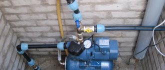
Rice. 2 Example of a borehole water intake source
Installing a submersible pump and connecting it to automation
The connection diagram for the submersible unit depends on what kind of automation is used for the pump, and it is usually reflected in the operating manual. As an example, let's look at the option of assembling a circuit with class 1 automation powered by a hydraulic accumulator.
These videos show you step by step how to install a submersible pump:
Work begins with tying the hydraulic accumulator. According to the diagram, equipment is connected to it one by one. All threaded connections are sealed with fume tape. In the photo you can see the order of assembly.
The first to screw onto the threads of the hydraulic accumulator is the “American” one. This detachable connection will be useful in the future for servicing the water storage tank, often associated with replacing the rubber membrane. A bronze adapter with threaded elbows is screwed onto the American free thread. A pressure gauge and pressure switch are screwed into them. Next, attach one end of the PVC supply pipe using an adapter fitting to the end of the bronze adapter on the hydraulic accumulator. The other end of the pipe is fixed with a fitting to the pump nozzle.
The supply pipe with the pump is laid on a flat area. A safety cable with a reserve length of about 3 m is attached to the loops on the body of the unit. The cable and cable are fixed to the pipe in increments of 1.5–2 m with plastic clamps. The free end of the cable is secured near the well casing. Now all that remains is to lower the pump inside the well and tighten the safety rope. The casing is covered with a protective cap to prevent clogging of the well.
When everything is ready, the cable is connected to the relay and led to the electrical control cabinet. After turning on for the first time, the pump will immediately begin pumping water into the hydraulic tank. At this stage, you must immediately open the water tap to bleed out the air.
When the water begins to flow evenly without air impurities, close the tap and look at the pressure gauge. Usually the relay is already adjusted to the upper water pressure parameter - 2.8 atm, and the lower limit - 1.5 atm. If the pressure gauge shows different data, the relay must be adjusted with the screws located inside the housing.
Video description
This video shows an analysis of the types of automation and its components:
See also: Companies specializing in equipment for water supply, heating, sewerage and septic tank systems.
Elements of the second generation system often fail because it operates at maximum performance during startup. In order to avoid breakdowns, careful adjustment of all parts or a frequency converter, which is installed in more expensive systems, is required. Automation for a pump without a hydraulic accumulator will fail faster than with an additional tank. Electronic units have a higher cost than mechanical ones.
For modular automatic control units, the performance directly depends on the network voltage, since if there is a lack of power, the motor will not operate at full power or will not start at all. Also, most well pump control units contain fixed settings that are suitable only for a certain engine model.
Automatic control module for pump Source cdek.market
Third generation
Third generation automation are devices that have the highest reliability, power and cost. It differs from its predecessor by the presence of speed control.
The most important part of this automation unit for a well pump with a hydraulic accumulator and a pressure switch is the frequency converter. It helps reduce engine load, extend operating time and reduce electricity use.
When the pump is running, this module independently reduces its power. For example, if you open only one tap, the system will not start at its limit, but after opening the second tap, the pressure will drop and the converter will increase the pressure.
Due to its high cost, a frequency converter is not often mounted in a control unit. It is recommended to install a small hydraulic accumulator with the automation for the well pump, which will prevent the frequency converter from restarting if there is a water leak.
Preparing the storage tank of the pumping station
Before adjusting the pressure switch itself, it is necessary to prepare the hydraulic accumulator. It consists of a sealed container and a rubber bulb that divides this tank inside into two parts. When water is pumped into the first, air pressure rises into the second. Then this air mass, by pressing on the bulb, will maintain the pressure in the water supply pipe.
Hydraulic accumulator (storage tank)
In order for the pumping station to operate in optimal mode, the air pressure for the hydraulic accumulator must be correctly selected. If you make it too high or low, the hydraulic pump will start working too often. Such a setting is a direct path to rapid wear of the equipment.
The required air pressure in the accumulator is set after it is completely emptied of water. After its descent, air is pumped in at the rate of 1.4–1.7 atmospheres for a tank of 20–25 liters and 1.7–1.9 atmospheres for a larger volume. Specific values should be found in the station data sheet.
Total pump automation
Gilex Crab automation unit is a device that automates the operation of an electric pump. It turns on the system when the pressure decreases (the valve opens), and turns it off when the flow stops (the valve closes). Automation also consists of protecting the pumping station when it is “idle” - operating without water, on “dry running”.
Characteristics of the Gilex automation unit
The automatic Gilex block applies only to clean water that does not contain solid elements. If the latter are available, then you need to separately purchase a filter element for the automation unit. And if you install a pressure gauge, the pressure can be monitored visually.
How it works?
The automatic unit Gilex 9001 turns on 30 seconds after connecting to the power supply. It then turns off and goes into sleep mode. Further switching on of the device occurs when the pressure changes - the valve opens and closes.
As soon as the pressure level drops to the minimum permissible norm, the automation control element will turn off the pump. This significantly extends the safety and performance of the device.
After the pressure drops to the minimum permissible level, the system will not turn off immediately, but after several tens of seconds (usually from five to twenty, depending on the specific model). A delay in turning off the pumps is necessary so that, with low water pressure, it does not systematically turn off. This allows you to extend the life of the system.
Automation block Jelex (Dzhileks): looking at the insides (video)
To automate the control of the pump, you need to purchase the appropriate additional components for it (depending on your needs), and connect them in the following sequence:
- The pressure gauge is attached to the automatic unit on the side using the fasteners included in the kit. Which side to mount on is “a matter of discretion.” But, it is important to carefully secure the device to the panel without using sealing elements.
- The automation unit is mounted exclusively in a vertical position. It can also be fixed in any convenient place, but in the section between the tap (the first water intake point) and the pump supply system. Moreover, this must be done so that the external inlet of the system is adjacent to the water outlet channel from the pump, and the side outlet is adjacent to the water flow in the pipe.
- All connections must be tightly fixed. It is worth making sure that they are tight and double-checking that all connecting elements are connected correctly.
- If automatic equipment is used for electric pumping systems with a maximum pressure threshold of 15 bar, then a pressure reducer is mounted at the input of the automation.
- The device body (or circuit board) contains an electrical circuit for connecting the automation. Follow it strictly when connecting! If a single or three-phase pump with an operating current of more than 10 Amps is used, the automation must be connected via an electromagnetic starter. The cable used to connect the device must be resistant to elevated temperatures (above 100 degrees) and non-flammable.
- Automatic adjustment and operation of systems (minimum pressure) is designed for a pressure of 2 atm. This option is the most common and optimal for most systems. But, this parameter can be easily adjusted if necessary. This is done by rotating the tap, which is located on top of the automatic system and has “plus” and “minus” markers.
Installation diagram of a water supply system with Gilex automation
Starting the automatic system
Important! When the incoming water level is lower than the level at which the pumping system is installed, it is imperative to install a check bottom valve on the inlet pipe.
We start the automation as follows:
- Immediately before turning on the device, completely fill the inlet pipe of the pump with water and start it (the “Network” LED should light up). This manipulation will turn on the automation unit. As soon as the pump starts working and stops after a while, you need to open the outlet valve, which is located at the highest point.
- If the pump runs all the time with the tap open and provides a continuous flow of water, the installation is considered correct. The absence of water flow indicates that you need to hold down the “Restart” button and hold it for as long as the automatic system operates. If after such manipulation the flow is still missing, you need to repeat the launch.
Idling protection
When the “Protection” LED on the automation unit lights up and the pump itself is turned off, this may indicate a danger of idle operation of the system. This is how press control works.
Recheck all systems. If everything is in order, drain the water from the incoming system and refill it. Then click the “Reboot” button.
How to choose the right model
When choosing a water pump model, take into account the following criteria:
- Source flow rate.
- Volume of fluid intake.
- Maximum number of starts in 1 hour.
- Fluid temperature.
- Electrical network parameters.
- Water quality, presence of inclusions and impurities, particle size.
- The depth to which the pump will be immersed.
In addition to these factors, the determining ones are:
- installation location;
- principle of operation of the mechanism;
- aquifer thickness;
- height of liquid rise;
- water pipe length;
- number of consumers.
Information about the source is recorded in the well passport. This document is issued upon completion of drilling work.
Water pump models Vodomet.
The main characteristics of the pump are indicated in the marking . The maximum flow rate of liquid during spouting is the largest amount of water unobstructed at the outlet in 1 minute. The parameter is determined by summing all water points (bath or shower, kitchen sink, etc.).
The second indicator is the maximum height of the water column when water intake points are closed, depending on the distance and height of the taps. The manufacturer produces units with a flow rate of 40, 55, 110 and 150 l/min and a head of 30, 35, 45, 50, 60, 75, 90, 110 and 160 m.
For wells with low flow rates, simple models are suitable, such as “Vodomet” 40/50 and 40/75, providing a flow rate of 40 l/min and raising water by 50 and 75 m, respectively.
With an average source productivity with a consumption of 2-3 m³/h, it is recommended to choose pumps that provide a flow rate of 60 l/min; this will be enough to supply water to 3-4 consumers.
With a nominal flow rate of 3-4 m³/h, it is better to buy equipment with a flow rate of 110 l/min. If the well has a high flow rate, a unit that pumps 150 liters of water per minute is suitable for uninterrupted operation of the water supply system.
If the dynamic level is no more than 5 m, pumps with a liquid column height of 30 or 35 m are suitable; for well depths up to 25 m, pumps of 45 or 50 m are suitable. If the static level is 25-45 m, units with a pressure of 60 or 75 m are selected For greater well depths, 90 or 110 m systems are suitable.
Some models, for example "Vodomet" 55/35, 55/50, 55/70, are equipped with a float switch. Such pumps are used in wells where there is space to install the mechanism.
Submersible units 55/35, 55/35A, 150/30A are not used in automatic water supply systems. These pumps do not have a pressure reserve and do not provide sufficient flow; the flow and pressure indicators are low.
Water pumps Vodomet.
Scope of equipment application
Vodomet submersible pumps from the domestic manufacturer Gileks are used in everyday life to install a water supply system and supply water from wells with a diameter of 100 mm or more, as well as tanks, wells and other open reservoirs. With their help, they transport water to the house and irrigate garden plots.
Pumps of the Vodomet PROF series, thanks to their innovative design and floating wheels, are capable of pumping water with a high concentration of solid impurities no larger than 1.5 mm in size.
Rules for installing and configuring AQUAROBOTA TURBIPRESS
The AQUAROBOT TURBIPRESS block is designed for automatic control of both surface and submersible pumps. This automation is compatible with single-phase pumping devices whose power does not exceed 1.5-2.2 kW.
The main functionality of the automation is as follows:
- pump control by maintaining user-specified upper and lower pressure in the system;
- turning off the pump if there is no possibility of water intake;
- maintaining the operating condition of the system when the voltage drops to 170 V.
"AQUAROBOT" has the following technical characteristics:
The connection diagram for a deep-well pump with automatic “TURBIPRESS” is standard
- permissible operating voltage – 170-250 V;
- maximum current – 16-20 A;
- maximum pump capacity – 120 l/min., minimum – 3 l/min.;
- pressure level for switching on – 0.5-4.5 bar, for switching off – 2-5 bar;
- protection response rate is 5.5-7 bar.
The connection diagram for a deep-well pump with automatic “TURBIPRESS” is standard: the unit is installed on the pressure pipe of the pump up to the first point of water consumption from the system.
It is not allowed to connect this automation to a system without a hydraulic accumulator. The minimum volume of the membrane tank must be at least 20 liters.
Important! When using a vertical hydraulic accumulator in the system, you cannot install the TURBIPRESS automation on the flange of the membrane tank.
“TURBIPRESS” automation cannot be connected to a system without a hydraulic accumulator
Advantages of Vodomet pumps
“Vodomet” is highly reliable, maintainable, resistant to voltage surges, and has a long service life. Maintenance of the pump is convenient and safe; settings and installation do not cause difficulties. To assemble the unit, materials are used that meet sanitary and hygienic standards and are suitable for contact with drinking water.
The devices operate silently, do not overheat and pump water from great depths. When developing water supply systems, the manufacturer took into account the wishes of users, so the pumps are adapted to local conditions and have a lower price than foreign analogues.
How to make a water pump with your own hands at home
Summer residents are not lazy and savvy people. Therefore, the question of how to make a water pump with your own hands without electricity is asked quite often. In fact, there are many options, all of them are quite feasible. One of the most effective and most affordable is a pump based on a pump mechanism. This is the type that is most often used in conditions where there is no electricity.
To create a pump you will need the following elements and parts:
- PVC pipe with a diameter of 5 cm;
- PPR pipe with a diameter of 2.4 cm;
- two 0.5 inch check valves;
- pipe plugs and bends;
- 8 mm bolts with nuts, rubber gaskets.
The pump is assembled from the above parts. The main thing is to ensure the tightness of the structure, otherwise the mechanism will not work. The piston creates pressure in the working chamber. Under its influence, water, passing through the valves, is supplied to the outlet. It is very important that the gaskets fit tightly.
Related article:
Pressure switch for a hydraulic accumulator: how to install and configure correctly
Purpose and installation location of the pressure switch. Rules for adjusting and configuring the device.
It is difficult to perceive when described, but in fact it does not cause problems to create a pump powered by solar energy with your own hands. The operating principle is somewhat reminiscent of how a submersible pump is connected to a hydraulic accumulator: gas takes part in pushing out water.
A pump based on a pump mechanism is the most affordable to make yourself
Required components:
- metal grate;
- rubber bulb;
- cylinder with propane-butane mixture.
The grate is filled with gas and connected to the bulb. The pear is placed in a tank pre-equipped with valves for inlet and outlet. Solar energy expands the gas, the latter pushes out air, providing a pressure difference in the water tank.
Important! All tank seams must be sealed tightly. Such a pump must be located in a well-lit place.
Design Features
Gilex hydraulic accumulators compare favorably with similar products from other manufacturers. Their developers took into account all the subtleties and nuances of the Russian water supply and achieved maximum adaptability to existing conditions. The reservoir has a relatively simple structure: a metal block, inside of which there is a pear-shaped rubber membrane. Between this membrane and the outer walls there is air in products for home use, and inert gas in industrial products.
A hydraulic accumulator differs from a simple barrel in that it must not only release water into the system, but also maintain a certain pressure in it.
The device is divided by a membrane into two lobes. The first part communicates with the external atmosphere through a nipple, and the second part is connected to the water supply network. When the tank is filled with water, the membrane stretches and presses on the gaseous medium until the pressure equalizes. When the tap is opened, compressed gas displaces liquid from the tank. As soon as the automation unit registers a reduction in pressure to a certain value, it gives the command to start the pump.
After closing the tap, the pump will continue to operate for some time, thereby achieving pressure equalization again. To ensure that pumps and membranes last as long as possible, cleaners must be installed at the inlet. In order for the hydraulic accumulator to work successfully and solve its problem 100%, a connection diagram must be thought through. In any case, it includes a pressure switch and a check valve. Experts advise installing a pressure gauge to reliably monitor changes in pressure in the system.
Hydraulic accumulators in a water supply network with a surface pump are usually placed next to the pumping machine. The check valve in this arrangement is located on the suction pipeline. To connect devices into one complex, a fitting with five terminals is used. Theoretically, it is possible to replace it with an arbitrary combination of pipe fragments, but this is too labor-intensive and not always of high quality. To securely fix the membranes and connect them to water pipes, it is recommended to use a stainless flange from leading manufacturers.
In particular, the Belamos SS modification is distinguished by such parameters as:
- connecting thread – 1 inch external;
- outside diameter – 160 mm;
- the gap between the attachment holes through the center of the part is 12.8 cm;
- the same gap between the centers of adjacent holes is 6.4 cm.
When choosing a flange, it is important to check whether it is compatible with hydraulic accumulators and expansion tanks from their manufacturers. The hydraulic accumulators themselves are divided into vertical and horizontal. The choice of a specific type is determined by how compact the device will be and whether it will be convenient to place it in a certain way. But it's not just about design and comfort. The approach to venting air outside is different.
Thus, in a vertical system, oxygen can be released using a safety valve - and it is sufficient. And horizontal devices require for this purpose the formation of a separate pipeline with a nipple and a ball valve.
Attention: vertically placed devices with a capacity of up to 100 liters can only be emptied of air if the liquid has been completely removed. In addition, a horizontal tank is much better suited for working with an external pump, while a vertical tank goes well with a submersible one.
Vertical systems will have to be chosen if you need a very large tank capacity, from 750 liters. This is ideal for additional liquid storage. But if simple designs are required that can be used in any place where there is enough space for them, then the choice of horizontal is already justified. Important: do not confuse hydraulic accumulators and expansion tanks, even though they look similar in many ways. The second type of device is used only in heating systems and is therefore always made of a material that can withstand high temperature and pressure.
A hydraulic tank for water supply is not designed for such extreme loads in principle. The purpose of their use is completely different - it is to reduce the number of pump starts, prevent water hammer and provide water for some time in the event of a power outage or breakdown of the pump or main line. Not only can hydraulic accumulators be used in heating circuits, reverse replacement is also unacceptable. After all, contact of water with the tank body will inevitably lead to its corrosion. It is important to remember this circumstance so as not to accidentally purchase a membrane heating tank instead of a water supply one.
The hydraulic accumulator is part of the Jumbo 60/35 pumping station. The 24L horizontal tank, covered by a general warranty, is made of carbon steel. In an empty tank, the pressure is 1.5 atm if measured inside the diaphragm. According to technical standards, it is prohibited to use the system to work with liquid heated to more than +50 degrees.
Attention: it is prohibited to start the system in dry mode.