A hydraulic accumulator (expansion membrane tank) serves to maintain pressure in a pressure water supply system, and when used in conjunction with a pressure switch, allows you to create an automatic station based on a submersible or surface pump. The main purpose of the hydraulic accumulator in the system is to maintain and smoothly change the fluid pressure in the system.
Additional functions performed by the hydraulic accumulator are as follows:
- Protection against water hammer (changes in fluid pressure caused by an instantaneous change in its speed)
- Ensuring a minimum supply of water
- Limitation of intermittent pump starts
Thus, it is the hydraulic accumulator that makes it possible to use a pressure switch and automate the water supply process. Without a hydraulic accumulator, the relay cannot work correctly, since an instantaneous change in pressure in the system (at the moment of opening a tap, disconnecting or connecting new consumers, turning a pump on or off, etc.) would cause the relay to constantly operate. And this, in turn, leads to instability of supply, overheating or breakdown of the electric motor, and breakdown of the relay.
Since water is practically incompressible, turning on a pump in a system with a pressure relay, but without a hydraulic accumulator, would cause an instant increase in pressure in the system and the relay would immediately react to this and turn off the pump. On the other hand, when the tap was opened, the pressure would immediately drop and the relay would react and turn on the pump.
Water compressibility coefficient = 5 x 10^10 1/ Pa. Those. An increase in water pressure (the pressure created by the pump) practically does not cause a change in its volume (these are hundredths of a percent). Therefore, the pressure in the system would change at a high speed, which would cause the relay to constantly operate.
It must be clearly understood that the hydraulic accumulator does not create any pressure and does not pump water to the consumer itself - all this is done by the pump. It only maintains the liquid pressure that is created in it by the pump and supplies water at that moment in time while the consumer’s tap is open and the pump is not turned on. For example, the question “What volume of hydraulic accumulator do I need if I have two showers?” not entirely correct. Because when using a shower (one or two), the hydraulic accumulator supplies water only until the pump is turned on, and then only the pump supplies water for the remaining time of use. And it will stop only after all the taps are closed and the pressure in the tank rises to the shutdown pressure.
Sometimes it happens that the pump turns off even while consumers are using water. However, this mode of operation is undesirable (since after a short time the pump will have to turn on again) and indicates that the selection of the pump and/or the settings of the entire system are incorrect (in most such cases it is necessary to change the settings of the pressure switch).
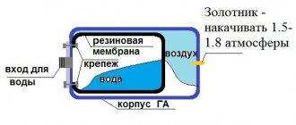
Any hydraulic accumulator is divided by a membrane into two cavities: air and water. By supplying water under pressure into the water cavity of the tank, the membrane expands and compresses the air in the air cavity. Thus, the membrane is balanced by pressure on both sides (P1V1 = P2V2). The pressure will increase until the pump is switched off at the pressure switch setting (pump cut-off pressure). At the moment water flow begins, air presses on the membrane, thereby pushing water out of the accumulator. The water pressure slowly drops and when the pump activation pressure is reached, the relay will close the contacts and the pump will start. This is the schematic diagram of the automatic operation of the pump together with a hydraulic accumulator and a pressure switch.
What should be the air pressure in the air cavity of the accumulator?
The pressure in the air cavity of the hydraulic accumulator should be 10% less than the pump activation pressure.
Moreover, the air pressure needs to be measured only with the tank disconnected from the system (without water pressure). Air pressure must be regularly monitored and, if necessary, brought back to normal; this will significantly extend the life of the membrane. For the same purpose, it is not recommended to make the pressure difference between turning the pump on and off too large. The optimal difference is 1.0-1.5 atm. Larger differences stretch (load) the membrane more, thereby reducing its service life, and moreover, large pressure differences are not comfortable when using water.
It is recommended to install hydraulic accumulators in places not subject to flooding and with low humidity. In this case, the accumulator flange will last much longer. Since the tank does not bear any load, there is no need for additional fastening. The hydraulic accumulator can simply be installed on the floor on standard supports.
When choosing a specific brand of hydraulic accumulator, you should pay attention to the membrane material, the availability of certificates and sanitary and hygienic certificates certifying that the hydraulic accumulator is intended for use in drinking water systems. It’s also a good idea to make sure you have spare membranes and flanges, so that in case of problems you don’t have to buy a completely new tank.
The maximum pressure for which the accumulator is designed should not be less than the maximum possible pressure in the system (for example, if the pressure switch breaks down). This is why most tanks are designed for a pressure of 10 bar.
The question often arises about how much water is in the accumulator?
For example, if the power goes out, how many liters of water can be used?
This value depends on the settings of the pressure switch. As you might guess, the higher the pressure difference between turning the pump on and off, the more water will enter the accumulator, however, this difference must be limited for the reasons stated above.
As an example, we provide a table of the filling capacity of hydraulic accumulators.
| P air, bar | 0,8 | 0,8 | 1,8 | 1,3 | 1,3 | 1,8 | 1,8 | 2,3 | 2,3 | 2,8 | 2,8 | 4,0 |
| P on pump, bar | 1,0 | 1,0 | 2,0 | 1,5 | 1,5 | 2,0 | 2,0 | 2,5 | 2,5 | 3,0 | 4,0 | 5,0 |
| P off pump, bar | 2,0 | 2,5 | 3,0 | 2,5 | 3,0 | 2,5 | 4,0 | 4,0 | 5,0 | 5,0 | 8,0 | 10,0 |
| Total tank volume, l | Water reserve, l | |||||||||||
| 19 | 5,70 | 7,33 | 4,43 | 4,99 | 6,56 | 2,53 | 7,09 | 5,37 | 7,46 | 6,02 | 8,11 | 8,35 |
| 24 | 7,20 | 9,26 | 5,60 | 6,31 | 8,28 | 3,20 | 8,96 | 6,79 | 9,43 | 7,60 | 10,24 | 10,55 |
| 50 | 15,00 | 19,29 | 11,67 | 13,14 | 17,25 | 6,67 | 18,67 | 14,14 | 19,64 | 15,83 | 21,33 | 21,97 |
| 60 | 18,00 | 23,14 | 14,00 | 15,77 | 20,70 | 8,00 | 22,40 | 16,97 | 23,57 | 19,00 | 25,60 | 23,36 |
| 80 | 24,00 | 30,86 | 18,67 | 21,03 | 27,60 | 10,67 | 29,87 | 22,63 | 31,43 | 25,33 | 34,13 | 35,15 |
| 100 | 30,00 | 38,57 | 23,33 | 26,29 | 34,50 | 13,33 | 37,33 | 28,29 | 39,29 | 31,67 | 42,67 | 43,94 |
| 200 | 60,00 | 77,14 | 46,67 | 52,57 | 69,00 | 26,67 | 74,67 | 56,57 | 78,57 | 63,33 | 85,33 | 87,88 |
| 300 | 90,00 | 115,71 | 70,00 | 78,86 | 103,50 | 40,00 | 112,00 | 84,86 | 117,86 | 95,00 | 128,00 | 131,82 |
| 500 | 150,00 | 192,86 | 116,67 | 131,43 | 172,50 | 66,67 | 186,67 | 141,43 | 196,43 | 158,33 | 213,33 | 219,70 |
| 750 | 225,00 | 289,29 | 175,00 | 197,14 | 258,75 | 100,00 | 280,00 | 212,14 | 294,64 | 237,50 | 320,00 | 329,55 |
| 1000 | 300,00 | 385,71 | 233,33 | 262,86 | 345,00 | 133,33 | 373,00 | 282,86 | 392,86 | 316,67 | 426,67 | 439,39 |
According to this table, in a 200 liter hydraulic accumulator with the following pressure switch settings: Pump on - 1.5 bar Pump off - 3.0 bar Air pressure - 1.3 bar
The water supply will be 69 liters, which is approximately a third of the total volume.
In conclusion, a few words about the required volume of the hydraulic accumulator.
V t = K x A max x ((P max +1) x (P min +1)) / (P max - P min) x (P air + 1)
A max - estimated maximum water flow (liter/min) K - coefficient depending on the power of the pump electric motor (see table below) P max - pump switch-off pressure, bar P min - pump switch-on pressure, bar P air. — pressure in the air cavity of the hydraulic accumulator, bar
| Pump power, kW | 0,55-1,5 | 2,2-3,0 | 4,0-5,5 | 7,5-9,0 | ||||||||
| Factor K | 0,25 | 0,375 | 0,625 | 0,875 | ||||||||
We will select the minimum required volume of the hydraulic accumulator for the water supply system based on the Aquarius BTsPE 0.5-50 U pump with the following settings:
P max = 3.0 bar P min = 1.8 bar P air. = 1.6 bar A max = 2.1 m³/h (35 l/min) K = 0.25 (since the pump power is in the range of 0.55–1.5 kW)
V t = 31.41 liter
We select the next closest volume of the hydraulic accumulator - 35 liters.
Note that the tank volume of 24-50 liters is in excellent agreement with other methods for calculating hydraulic accumulators for domestic water supply systems and empirical recommendations of various manufacturers of pumping equipment.
A larger volume should be chosen if there are frequent power outages, but it must be remembered that in any case, water fills approximately a third of the total volume (see the occupancy table above). And of course, the more powerful the pump is installed in the system (relevant for pumps with a power of 1.1 kW and above), the larger the size of the hydraulic accumulator should be preferred, this will reduce the number of repeated short-term starts and extend the service life of the pump motor.
When purchasing large-volume hydraulic accumulators, you must be aware that water must be used regularly, since with prolonged inactivity, its quality begins to deteriorate. After all, using all the water from a hydraulic accumulator with a volume of 24 or 50 liters is much easier and faster than from a 100 or 200 liter one.
Models and prices for hydraulic accumulators can be found in the section “
And one question remained unclear: when to inflate the accumulator with air, before filling with water or after? Logically, it seems that you need to pump up before, but after searching the answer on the Internet, it turned out that some recommend doing this after.
In general, it is correct to pump the accumulator dry until it is filled with water.
To calculate the required pressure in the air part of the accumulator, you can use formulas; if you are lazy, then the air pressure in the accumulator is calculated using a very simple formula, it should be 10% less than the pressure at which the pressure switch turns on the pump. Typical values of the minimum and maximum pressure values at which the pump turns on and off are 1.5 and 3 bar, subtract 10% from 1.5 bar and get 1.35 bar of air we need to pump into the accumulator.
If you don’t like this calculation, you can use a more scientific approach:
Also keep in mind that the hydraulic accumulator requires periodic maintenance. Water always contains a small part of dissolved air, and this air gradually reduces the useful volume of the bulb (rubber membrane) in the accumulator. On large-capacity hydraulic accumulators, as a rule, there are special valves for releasing this air; in small hydraulic accumulators, which are usually equipped with household pumping stations, there are no such valves, and to remove air from the membrane, a simple operation must be performed every couple of months.
1. It is necessary to turn off the power to the pump and drain all the water from the accumulator; it is best, of course, to provide a special tap for this, or use the tap closest to the accumulator.
2. The procedure from point 1 must be done 2-3 times in a row.
And please do not confuse the hydraulic accumulator and the water storage tank, these are different devices, the hydraulic accumulator is designed to reduce the number of pump starts, and as a result increase its service life, as well as to protect against water hammer; in the event of a power outage, the hydraulic accumulator will of course supply water for some time you with water, but I wouldn’t count on much. In case of power outages or water supply breakdowns, a storage tank is needed.
Pressure switch
- an element that controls the operation of a pumping station (for example AQUAJET or AQUAJET-INOX) and which makes it possible to operate it in automatic mode. The pressure switch has several characteristics:
- Turn-on pressure
(
P on
) is the pressure (bar) at which the pumping station is turned on by closing the contacts in the pressure switch. Sometimes the switching pressure is also called “lower” pressure. - Switch-off pressure
(
P off
) is the pressure (bar) at which the pumping station is switched off by opening the contacts in the pressure switch. Sometimes the shutdown pressure is also called “upper” pressure. - Pressure drop
(
ΔP
) is the absolute difference between the cut-out pressure and the cut-in pressure (bar). - The maximum shutdown pressure
is the maximum pressure (bar) at which the pumping station can be turned off.
Any pressure switch has factory settings and, as a rule, they are as follows: Switch-on pressure: 1.5-1.8 bar Switch-off pressure: 2.5-3 bar Maximum switch-off pressure: 5 bar
How it all works:
Let’s say the pumping station is connected (more on this in the article “Preparing the DAB pumping station for operation”), and the entire system is filled with water. After opening any tap (shower, sink, etc.) and starting to draw water, the pressure in the system will begin to drop smoothly (thanks to the membrane hydraulic tank), which is easy to track with a pressure gauge. All this time, water is supplied to the consumer from the hydraulic tank. When the “lower” switching pressure is reached (it can also be monitored by a pressure gauge at the moment the pump is switched on), the contacts inside the pressure switch will close and the pump will start. The rest of the time of water collection, the pump continues to operate, supplying water directly to the consumer. After the water withdrawal is completed (all taps are closed), the pump still continues to work, only now the water is not supplied to the consumer, but is pumped into the hydraulic tank (since it has nowhere else to go) and the pressure gradually increases. When the shutdown pressure is reached (can be easily monitored on the pressure gauge when the pump stops), the contacts inside the pressure switch open and the pump stops. At the next water draw, the cycle repeats. It's quite simple.
But what to do if the factory settings of the pressure switch are not very comfortable? For example:
on the upper floors the pressure drops very noticeably, or the water purification system requires at least 2.5 bar at the inlet, while the pump turns on only at 1.5-1.8 bar.
Criterias of choice
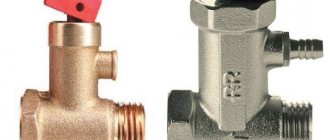
When choosing a regulator, be sure to pay attention not only to the design of the device and its technical characteristics, but also to the material from which it is made. . Design features
Design features
Modern RDVs, depending on their design, are divided into piston and membrane. Despite the fact that the piston practically does not wear out, gearboxes of the first type are less reliable. This is due both to sensitivity to the purity of water (the piston can jam due to particles of dirt or sand), and to the possibility of corrosion of structural elements.
Membrane-type RDVs are unpretentious in maintenance, since the diaphragm divides their working space into two chambers. One of them is completely sealed from contact with water. As you probably already guessed, it is in this half that most of the gearbox parts are installed. If the operating rules are followed, the operation of the device does not require intervention, so the only drawback can be considered the need to regularly monitor the integrity of the membrane.
Technical specifications
Household gearboxes produced by industry are designed for different inlet and outlet pressures. For example, a device that allows connection to a 15 bar line can provide output parameters within the range of 1–4 bar. To avoid confusion in terms, the value of 1 bar is often taken to be equal to 1 atmosphere, although in fact 1 bar = 0.987 atm. The outlet pressure of household regulators ranges from 0.5 to 4 atm or from 1 to 6 atm. To determine which device you need, look at the connection requirements for the equipment installed in your home. Most often, the manufacturer indicates them in the technical data sheet or a special plate mounted on the rear panel.
The second important parameter when choosing is the operating temperature of the RDV. Devices designed for a temperature range of 0–40 ºС can only be used when used in cold water systems. If you need a device for “hot” water supply, choose a device that operates in the range of up to 130 ºС.
Material and workmanship
Like other plumbing fittings, pressure regulators must be made of durable metals and alloys - steel, brass, bronze, etc. In addition, alloys that include iron must contain alloys with anti-corrosion properties. In practice, in retail chains you can find both very worthy products, distinguished by high quality workmanship, and outright rubbish. “Separating the wheat from the chaff” is easy thanks to two criteria – price and weight. Firstly, a good thing cannot be cheap, and secondly, pick up the products you are comparing and choose the one whose weight differs more. In addition, be sure to pay attention to the quality of the casting. Remember that a good manufacturer will never release a product with shells or flaking on the walls outside its workshops.
You can set the pressure switch yourself:
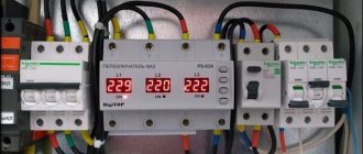
Using a pressure gauge, we record the on and off pressure when the pump is running. Turn off the power to the pump and remove the top cover of the pressure switch (usually by unscrewing one screw). You will see two screws, one larger one is located on the top of the relay, and the second, slightly smaller one, is located below it. The top screw is responsible for the shutdown pressure and, as a rule, next to it there is the letter “P” and an arrow with the signs “+” and “-”. Then we rotate the screw in the desired direction (if the shutdown pressure needs to be raised, then rotate in the direction of the “+” sign, if lowered, then in the direction of the “-” sign). How much to rotate? Make a turn (half a turn, one and a half - as much as you want). After this, we start the pump and see at what pressure it turns off now. We remember, turn off the power to the pump, and rotate the screw further, start the pump again and write down the new value, thus getting closer to the desired value.
The lower screw is responsible for the difference between the cut-off pressure and the cut-in pressure. As a rule, “ΔP” is written next to it and there is an arrow with “+” and “-” signs. Setting the pressure difference is similar to setting the cut-off pressure. There is only one question left: what should it be? The difference between switch-on and switch-off pressure is usually 1.0-1.5 bar. Moreover, the higher the shutdown pressure, the greater this difference can be. For example, with factory settings P on = 1.6 bar, P off = 2.6 bar, the difference is 1 bar, this is exactly the standard value. If we want to change the factory settings and raise P off to 4 bar, then the difference can be made by 1.5 bar, i.e. P on should be set at 2.5 bar. You must understand that the greater this difference, the higher the pressure drop in the system, which is not always comfortable. But at the same time, the pump will turn on less often, and more water will flow from the hydraulic tank before the pump turns on.
This is only true if the pump can provide the required pressure (see pump characteristics). Those. if the pump can only produce 3.5 bar according to its passport (taking into account all types of losses), then setting the pressure switch to turn off 4 bar will not do anything. The pump simply will not be able to provide the required pressure and in this case will work without stopping. And if you still need exactly 4 bar, then you will have to change the pump to a more powerful one.
What should the air pressure be in the air cavity of the hydraulic tank?
Many people don’t think about it, or simply don’t know that they need to keep an eye on this. Unfortunately, yes, it is necessary; the service life of the hydraulic tank membrane, and ultimately the pump, directly depends on this.
We measure the air pressure in the air cavity of the hydraulic tank. We do this only with the hydraulic tank disconnected from the system.
— turn off the power to the pump, open any tap behind the pump and wait until the water comes out of the hydraulic tank.
Or we measure it on an installation that is not yet connected to the water supply system. To do this, remove the decorative cap from the air nipple of the hydraulic tank and connect a regular car pressure gauge to it (to check the pressure in the car tires). Let's remember this pressure. (As a rule, on small hydraulic tanks with a capacity of up to 50 liters, this pressure will be 1.5 bar). Now the most important rule : the air pressure in the hydraulic tank should be less than the pump activation pressure by about 10%
. Those. if the pump activation pressure is 1.6 bar, then the air pressure should be 1.4-1.5 bar. In most cases, these are the factory settings mentioned above. Those. By purchasing a ready-made pumping station, you already have a fully configured system. But once you have made changes to the factory settings of the pressure switch, you must always change the air pressure in the hydraulic tank. For example, if you set P on = 2.5 bar, P off = 3.5 bar, then it is necessary to raise the air pressure to a value of 2.2-2.3 bar.
By the way, even if you haven’t changed anything in the factory settings, you need to regularly monitor the air pressure, or at least check it once a year at the beginning of the summer season. It is important that this pressure be constant, but if it has dropped a little over the winter, it can always be raised with a regular car pump to the required level.
All these simple operations will not take much time; it is enough to pay attention to them once a year, especially since everything will pay off in the long and uninterrupted operation of the entire water supply system as a whole.
2007 website Setting the pressure switch and adjusting the air pressure in the accumulator.
To prevent the pump from turning on every time a faucet is opened in the house, a hydraulic accumulator is installed in the system. It contains a certain volume of water, sufficient for a small flow rate. This allows you to practically get rid of short-term pump starts. Installing a hydraulic accumulator is not difficult, but you will need a few more devices - at least a pressure switch, and it is also desirable to have a pressure gauge and an air vent.
Do I need to repeat the procedure?
It may be necessary to revise the adjusted parameters only if the operating mode of the equipment changes.
The following situations may force you to do this:
- change in the number of family members;
- transfer of the installation along with the house or cottage to new residents;
- installation of a hydraulic accumulator of a different volume.
In order to maintain stable operation of the system in accordance with the settings, the amount of air in the storage tank is checked once a quarter.
Functions, purpose, types
Installation location - in a pit or in a house
In the water supply system of a private house without a hydraulic accumulator, the pump turns on whenever water flows somewhere. These frequent starts lead to wear and tear on the equipment. And not only the pump, but the entire system as a whole. After all, every time there is an abrupt increase in pressure, and this is a water hammer. To reduce the number of pump starts and smooth out water hammer, a hydraulic accumulator is used. The same device is called an expansion or membrane tank, a hydraulic tank.
Purpose
We found out one of the functions of hydraulic accumulators - to smooth out water hammer. But there are others:
It is not surprising that most private water supply systems have this device - there are many advantages from its use.
Kinds
The hydraulic accumulator is a tank made of sheet metal divided into two parts by an elastic membrane. There are two types of membrane - diaphragm and balloon (bulb). The diaphragm is attached across the tank, a pear-shaped cylinder is secured at the inlet around the inlet pipe.
According to their purpose, they are of three types:
- for cold water;
- for hot water;
- for heating systems.
Hydraulic tanks for heating are painted red, tanks for water supply are painted blue. Expansion tanks for heating are usually smaller in size and lower in price. This is due to the membrane material - for water supply it must be neutral, because the water in the pipeline is potable.
Depending on the type of arrangement, hydraulic accumulators can be horizontal or vertical. Vertical ones are equipped with legs; some models have plates for hanging on the wall. It is the elongated upward models that are most often used when independently creating water supply systems for a private home - they take up less space. The connection of a hydraulic accumulator of this type is standard - through a 1-inch outlet.
Horizontal models are usually equipped with pumping stations with surface-type pumps. Then the pump is placed on top of the tank. It turns out compact.
Principle of operation
Radial membranes (in the form of a plate) are used mainly in gyroaccumulators for heating systems. For water supply, a rubber bulb is usually installed inside. How does such a system work? As long as there is only air inside, the pressure inside is standard - the one that was set at the factory (1.5 atm) or that you set yourself. The pump turns on, begins to pump water into the tank, and the pear begins to increase in size. Water gradually fills an increasingly larger volume, increasingly compressing the air that is located between the wall of the tank and the membrane. When a certain pressure is reached (usually for one-story houses it is 2.8 - 3 atm), the pump is turned off, and the pressure in the system stabilizes. When you open a tap or other water flow, it comes from the accumulator. It flows until the pressure in the tank drops below a certain level (usually about 1.6-1.8 atm). After which the pump turns on, the cycle repeats again.
If the flow rate is large and constant - you are filling a bathtub, for example - the pump pumps water in transit, without pumping it into the tank. The tank begins to fill after all the taps are closed.
A water pressure switch is responsible for turning the pump on and off at a certain pressure. In most hydraulic accumulator piping schemes, this device is present - such a system operates in optimal mode. We’ll look at connecting the hydraulic accumulator a little lower, but for now let’s talk about the tank itself and its parameters.
Large tanks
The internal structure of hydraulic accumulators with a volume of 100 liters and above is slightly different. The pear is different - it is attached to the body both at the top and bottom. With this structure, it becomes possible to fight the air that is present in the water. To do this, there is an outlet in the upper part into which you can connect a valve for automatic air release.
Engine malfunction
If during the inspection the engine stops and there is no characteristic noise, then we can talk about the following:
- There is no connection to the electrical network or the voltage is too low. The solution to the problem is to check the equipment connection diagram.
- Fuse blown. In this case, the element must be replaced.
- The impeller is jammed. Difficult turning of the impeller indicates that it is jammed, so first of all you need to find out what caused this situation.
- Damaged relay. The solution to such a malfunction will be to adjust the relay or completely replace it, for which you need to know the design of the pressure switch at the pumping station.
Don’t think that engine problems can always be fixed on your own. In most cases, only specialists from the service center can solve problems.
How to choose tank volume
You can choose the tank volume arbitrarily. There are no requirements or restrictions. The larger the volume of the tank, the greater the supply of water you will have in case of a shutdown and the less often the pump will turn on.
When choosing a volume, it is worth remembering that the volume that appears in the passport is the size of the entire container. There will be almost half as much water in it. The second thing to keep in mind is the overall dimensions of the container. A 100 liter tank is a decent-sized barrel - about 850 mm high and 450 mm in diameter. You will need to find a place somewhere for it and the harness. Somewhere - this is in the room where the pipe from the pump comes. This is where all the equipment is usually installed.
If you need at least some guidelines to select the volume of a hydraulic accumulator, calculate the average flow rate from each water intake point (there are special tables or you can look at the data sheet for household appliances). Sum up all this data. Get the possible consumption if all consumers work simultaneously. Then figure out how many and which devices can work at the same time, calculate how much water will be consumed in a minute in this case. Most likely by this time you will have already come to some decision.
To make it a little easier, let’s say that the hydraulic tank volume of 25 liters is enough to meet the needs of two people. It will ensure the normal functioning of a very small system: a faucet, a sink and a small one. If you have other household appliances, the capacity must be increased. The good news is that if you decide that the current tank is not enough for you, you can always install an additional one.
What does the pumping station consist of?
An important element for the normal functioning of any pumping station is pressure. Before you find out what reasons exist that affect pressure, it is worth understanding what elements the device consists of:
- Pump.
- Hydraulic accumulator.
- Pressure switch.
- Pressure gauge.
What should be the pressure in the accumulator?
One part of the accumulator contains compressed air, and water is pumped into the second. The air in the tank is under pressure - factory settings - 1.5 atm. This pressure does not depend on the volume - it is the same on a tank with a capacity of 24 liters and 150 liters. The maximum permissible maximum pressure may be more or less, but it does not depend on the volume, but on the membrane and is indicated in the technical specifications.
Preliminary check and pressure correction
Before connecting the accumulator to the system, it is advisable to check the pressure in it. The settings of the pressure switch depend on this indicator, and during transportation and storage the pressure could drop, so monitoring is very desirable. You can control the pressure in the hover tank using a pressure gauge connected to a special input in the upper part of the tank (capacity of 100 liters or more) or installed in its lower part as one of the piping parts. Temporarily, for control, you can connect a car pressure gauge. Its error is usually small and it is convenient to work with. If this is not the case, you can use the standard one for water pipes, but they are usually not very accurate.
If necessary, the pressure in the accumulator can be increased or decreased. There is a nipple at the top of the tank for this purpose. A car or bicycle pump is connected through the nipple and the pressure is increased if necessary. If it needs to be vented, the nipple valve is bent with some thin object, releasing the air.
What air pressure should be
So should the pressure in the accumulator be the same? For normal operation of household appliances, a pressure of 1.4-2.8 atm is required. To prevent the tank membrane from tearing, the pressure in the system should be slightly higher than the pressure of the tank - by 0.1-0.2 atm. If the pressure in the tank is 1.5 atm, then the pressure in the system should not be lower than 1.6 atm. This value is set on the water pressure switch, which works in tandem with the hydraulic accumulator. These are the optimal settings for a small one-story house.
If the house is two-story, you will have to increase the pressure. There is a formula for calculating the pressure in the hydraulic tank:
Vatm.=(Hmax+6)/10
Where Hmax is the height of the highest point of water intake. Most often this is a shower. You measure (calculate) at what height relative to the hydraulic accumulator its watering can is located, substitute it into the formula, and get the pressure that should be in the tank.
If the house has a jacuzzi, everything is more complicated. You will have to select it empirically - changing the relay settings and observing the operation of water points and household appliances. But at the same time, the operating pressure should not be greater than the maximum permissible for other household appliances and plumbing fixtures (indicated in the technical specifications).
Area of use of the device
The pressure reducer simultaneously performs several functions. First of all, it is used to protect plumbing fixtures from high pressure. Thus, most plumbing fixtures and household appliances are designed to operate when the water pressure in the pipeline does not exceed 3 Atm. If this indicator is slightly higher, then the water supply system is under serious stress. Subsequently, valves, connections and other elements of the system and plumbing fixtures suffer
The gearbox is also used to combat water hammer, which can occur both in industrial enterprises and in residential buildings. As a result of a sharp jump in water pressure in the water supply system, a hydraulic shock occurs, which can damage the structural elements of the system. There are cases when such a sharp jump led to a rupture of the boiler. Therefore, experts recommend installing a gearbox, as it will prevent such problems from occurring.
It is very important to consider the installation in the system.
How to choose
The main working body of the hydraulic tank is the membrane. Its service life depends on the quality of the material. The best membranes today are made from isobutated rubber (also called food grade). The body material only matters in membrane-type tanks. In those in which a “pear” is installed, water comes into contact only with rubber and the material of the body does not matter.
The flange should be made of thick galvanized steel, but better - stainless steel
What's really important about bulb tanks is the flange. It is usually made of galvanized metal. In this case, the thickness of the metal is important. If it is only 1 mm, after about a year and a half of operation, a hole will appear in the metal of the flange, the tank will lose its tightness and the system will stop working. Moreover, the warranty is only one year, although the stated service life is 10-15 years. The flange usually deteriorates after the warranty period expires. There is no way to weld it - the metal is very thin. You have to look for a new flange at service centers or buy a new tank.
So, if you want the accumulator to last a long time, look for a flange made of thick galvanized or thin, but made of stainless steel.
List of common breakdowns
Typical causes of automation problems include:
burnt contacts;- salt deposits on the coils;
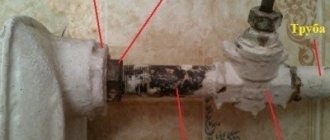
- clogged and rusty hydraulic inlet;
- the entry of sand and other foreign particles into the membrane compartment and the formation of deposits;
- incorrect mechanical settings of the automation.
Another reason for a failure to pump water, which is not directly related to a malfunction of the relay itself, can be voltage surges in the electrical network.
Connecting the accumulator to the system
Typically, the water supply system of a private home consists of:
This scheme may also include a pressure gauge for operational pressure control, but this device is not necessary. It can be connected periodically to carry out test measurements.
With or without five-pin fitting
If the pump is of a surface type, the hydraulic accumulator is usually placed next to it. In this case, the check valve is installed on the suction pipeline, and all other devices are installed in one bundle. They are usually connected using a five-pin fitting.
It has terminals with different diameters, just for the devices used for tying the hydraulic accumulator. That’s why the system is most often assembled on its basis. But this element is not at all necessary and everything can be connected using ordinary fittings and pieces of pipe, but this is a more labor-intensive task, and there will be more connections.
How to connect a hydraulic accumulator to a well - diagram without a five-pin fitting
With one inch outlet, the fitting is screwed onto the tank - the pipe is located at the bottom. A pressure switch and pressure gauge are connected to the 1/4 inch outlets. The remaining free inch terminals are connected to the pipe from the pump and wiring to consumers. That's all for connecting the gyroaccumulator to the pump. If you are assembling a water supply circuit with a surface pump, you can use a flexible hose in a metal winding (with inch fittings) - it is easier to work with.
A visual diagram of connecting the pump and accumulator - use hoses or pipes where necessary
As usual, there are several options, the choice is yours.
The hydraulic accumulator is connected to the submersible pump in the same way. The whole difference is where the pump is installed and where the power is supplied, but this has nothing to do with the installation of the accumulator. It is placed in the place where the pipes from the pump enter. Connection is one to one (see diagram).
How to install two hydraulic tanks on one pump
When operating the system, sometimes owners come to the conclusion that the available volume of the accumulator is not enough for them. In this case, you can install a second (third, fourth, etc.) hydraulic tank of any volume in parallel.
There is no need to reconfigure the system; the relay will monitor the pressure in the tank on which it is installed, and the viability of such a system is much higher. After all, if the first accumulator is damaged, the second one will work. There is another positive point - two tanks of 50 liters each cost less than one of 100. The point is that the technology for producing large-sized containers is more complex. So it is also more economical.
How to connect a second accumulator to the system? Screw a tee onto the input of the first one, connect the input from the pump (five-pin fitting) to one free output, and connect the second container to the remaining free one. All. You can test the circuit.
Set filters
Two filters for cleaning. Self-washing and polypropylene thread
Initially, the design and connection of a pumping station requires compliance with the requirements of the established regulations for the general operation of the entire structure as a whole. For primary water purification, the presence of certain cleaning elements is required. A common option is to install mechanical cleaning filters at the water supply inlet before the pumping station.
The first filter consists of a plastic flask with a mesh inside to collect large debris particles. The next cleaning element is installed immediately after the first, consisting of a flask with a polypropylene thread filter installed inside. With its help, the final filtration (purification) of water entering the main water supply of the house occurs.
Typically, both filters are used not only for water supply. Experienced designers, in parallel with the water supply, use a filter at the outlet for the storage tank. That is, filtered water can be supplied directly to the house, or through a storage tank. This could be a water heater, a large backup storage tank, etc.