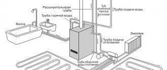
To ensure comfortable living conditions in a country house, a wide variety of equipment is installed. In the absence of electricity or interruptions in its supply, the generator is connected to the network of the country house. Such a device is designed to convert mechanical energy into electricity.
The generator connection diagram used must be safe, since voltage surges can cause malfunction of household appliances. Before connecting the generator, you should pay attention to useful recommendations.
Common mistakes
If the generator is connected incorrectly, not only the household appliances used can be damaged, but also the electrical wiring of the house and the device itself. A common mistake is when a mini-power station is connected to the electrical wiring through an outlet, bypassing the machines. The use of such a scheme is unacceptable for the following reasons:
- The generator power may be higher than the wiring capacity. In addition, the capacity of the sockets is no more than 3.5 kW. Too high a load causes the wiring to overheat, the insulation loses its properties, and a short circuit occurs. Too much heat can even cause a fire.
- A similar scheme for connecting a generator to a house is characterized by the fact that when the machine is turned on, the mini-power station breaks down. Such equipment is intended solely for the delivery of electricity, and not for the purpose of consuming it.
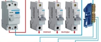
When considering how to connect a generator to a house, you should pay attention to a diagram that involves the use of a changeover switch or reversing switch. In addition, an automatic reserve start system can be used.
Automatic manual autostart of backup generator
If you have the skills, you can implement a circuit that automatically starts a gasoline electric generator when the network is de-energized. Use a key start/stop backup station model. For a product with a starter, when you have to pull the cord, theoretically this can also be done, but this option is too complicated and not worth the effort.
To better understand the operating principle of autorun, you need to familiarize yourself with the order of manipulations that are usually performed:
- After 1–2 minutes. after the main line is turned off, open the engine air intake and start it. The delay is needed just in case, to eliminate situations where the light blinked and immediately appeared again.
- Wait 2 minutes. - this is warming up, switch the load from the main line to the generator, close the air damper.
- After the main line is restored to service, 30–60 seconds later. They turn off the backup source and switch the load to it.
Implementation of automation
To implement the automation of the described algorithm, you will need to mount 4 pieces. pause relays, EM starters, magnetic pushers with limit switches (reminiscent of servo units for car locks). In fact, this will be a homemade AVR.
The EM starter has a coil (KM), and normally disconnected power contacts (KMk) and 2 control contacts (KMnr1 - 2), as well as 2 normally closed control contacts (KMnr1 - 2).
Autostart circuit algorithm:
- When the main line becomes inoperative, the KM4nz2 contacts close on KM4, and the engine ignition is activated.
- At KM1, KMk1 is disconnected - the line is disconnected from the home network.
- At the same time, KM1nz1 and 2 converge, the servo drive removes the air seal, an impulse is sent to delay relay 1. After 1 minute. the key contact will be closed and the starter will start.
- The start initiates activation of KM3, KM3nz1 and 2 open, the starter stops, and Serovodrive-1 is de-energized. At the same time, KM1nz2 converge - the pulse arrives at another delay relay, after 2 minutes. Servo-2 starts, the air intake closes, KM2 operates, which closes KMk2, the current is then supplied to the object by the backup station.
Choosing the right model
There are a variety of generator models on sale. Many are intended for use on construction sites or in industrial buildings. A home power plant is represented by an internal combustion engine, which is connected to a generator. It is the generator that produces electricity by converting mechanical energy. For home use, in most cases, they choose a four-stroke model with a rotation speed of up to 3,000 rpm, and the fuel tank volume is 10-15 liters.
When choosing, pay attention to the following characteristics:
- Power.
- Economical.
- Motor resource.
- Comfort in use.
- Reliability.
The power is selected depending on how much equipment will be powered by the generator. Profitability largely depends on the characteristics of the used internal combustion engine and generator. Comfort in use depends on the following indicators:
- Design dimensions.
- Noise during operation.
- Features of control, connection and fuel filling.
Reliability depends on the popularity of the brand under which the generator is produced.
The main question when choosing is also the purpose of the device. In most cases, it is purchased for backup use when an emergency occurs on the line. An example is the case of heavy snowfall. A mini-power plant is used extremely rarely as the main power source.
Connecting a device requires the coordinated work of several elements:
- Home consumption network.
- Central power supply circuit.
- Cables from reserve.
On sale you can find a variety of options for mini-power plants for the home. Gasoline models are the most popular:
- Big choice.
- Power suitable for domestic use: from 0.8 to 12 kW .
- There are compact models on sale that do not take up much space.
- Single-phase models are sold for home use, but a three-phase version can also be purchased.
- Reliable operation and low noise level.
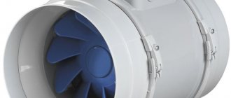
The cooling scheme depends on whether the generator will be used constantly or only as a backup source. Many models not intended for long-term use are equipped with air fans. If the device will work around the clock, then you should choose a water-cooled model.
There are also diesel generators on sale, which are installed extremely rarely today due to their high cost and complexity. Their use is advisable only in cases of large volumes of work.
Installations for generating current are divided into several main types:
- Asynchronous - characterized by simplicity and reliability. Modern models have a housing that protects the main components from dust and moisture. It is recommended to purchase similar models for active loads.
- Synchronous units are devoid of almost all the disadvantages that are inherent in asynchronous ones. Design features allow you to maintain voltage with greater accuracy. It is recommended to choose a brushless model , as it is characterized by better performance.
- Inverter ones are much more expensive than previous versions. At the same time, the design is less reliable and the device performs worse in operation: it cannot maintain a constant voltage.
If there are no three-phase consumers, you should purchase a single-phase generator. This is due to the fact that the three-phase model is more expensive.
Device and main parameters of generation
Three-phase generator design
A three-phase generator is a device that operates on the principle of converting the mechanical energy of a rotating shaft into electricity. In addition to the moving part associated with the drive, it consists of three coils made up of many windings and placed on the stator core. In brushless generators, when the rotor rotates, an EMF is induced in the coils, whose parameters correspond to the standards of 3-phase mains power. This means the following:
- the resulting voltages have a sinusoidal shape;
- the amplitude of each of the 3 phases is 220 Volts;
- the voltage between them is 380 Volts;
- frequency of generated oscillations – 50 Hz.
A design feature of such units is a phase shift of 120 degrees.
An alternating voltage is supplied from the stator coils to the serviced line, providing it with the necessary power of 380 Volts.
Connection features
When looking for an answer to the question of how to connect a generator to the home network (the connection diagram between the energy source and the consumer may differ depending on the characteristics of the house), you should answer several questions:
- How often does the central power supply network break down and is automatic connection of a reserve required?
- What is the total power of consumers taking into account losses (power reserve is taken into account).
- Where the device can be safely placed and connected to the system.
The use of automation significantly increases costs during installation work. In case of rare power outages, it is recommended to install a manual switch, which has a long service life and high reliability.
When calculating the required generator power, the following are taken into account:
- Total consumer power of all equipment.
- A reserve of 30%, which is designed for a higher starting current and the connection of additional equipment.
The connection diagram can be simple. It is important to compose it correctly and protect the generator itself and consumers from high loads.
How to perform grounding and lightning protection of a diesel generator set?
Networks with a rated voltage of up to 1 kV, powered by step-down transformers connected to networks with Un > 1 kV, are carried out with solid neutral grounding. Networks with Unom up to 1 kV, powered from an autonomous source or an isolation transformer (according to the condition of ensuring maximum electrical safety in case of ground faults), are carried out with an ungrounded neutral. Networks with Un = 110 kV and higher are carried out with effective neutral grounding (the neutral is grounded directly or through a small resistance). Networks 3 - 35 kV, made by cables, with any ground fault currents are carried out with grounding of the neutral through a resistor. 3-35 kV networks with overhead lines with a circuit current of no more than 30 A are carried out with the neutral grounded through a resistor.
Applicable schemes
There are several connection schemes, each of them has its own characteristics. The most commonly used methods for using an additional power source are:
- Direct connection of the reserve to the selected group of consumers.
- Via a three-position switch or changeover switch. In this case, you can provide power to all outlets and switches in the house if the wiring is designed to handle the generator's power. The disadvantage of this scheme is that three-phase equipment will not work.
- Creating two contacts: one will work from the city network, the second from a backup source. This method involves the use of ABP.
Connection via ABP
If problems frequently arise with city power supply, it is advisable to use a scheme with ABP. A special device controls the external network almost immediately after it is turned on. The installed machine, before connecting the generator, pauses for about 10 seconds from the moment of voltage loss from the main source, then turns off the main network. It takes about 20 more seconds for the mini-power plant to gain the required power. After the voltage from the main source is lost, the system takes about 30-40 seconds to supply electricity from the backup generator.
The connection diagram in this case looks like this:
- The local power supply supplies current to the meter through the circuit breaker on the ABP.
- The ABP is connected in parallel with the generator.
- After the ABP there is another circuit breaker.
This scheme is very convenient to use, but is very expensive.
After voltage appears on the external network, the backup power source is turned off, and the home network returns to normal operation. Such a scheme requires periodic maintenance.
Changeover switch
To reduce the cost of installation work when connecting an autonomous power source, you can use a changeover switch. This connection method has the following features:
- The middle contacts of the switch are connected to the load network.
- The extreme contacts are used to connect the home network with the power plant and the city power supply network.
- It is recommended to choose a switch model that has an additional intermediate position.
In the normal state, the switch supplies current from the city network; when switching, consumers will be powered by the generator.
a large number of old-style switches on sale . They are characterized by the fact that they can spark when changing the position of the handle. Modern versions have a protective casing, which significantly increases the reliability of the design.
Reversing switch
To connect a gas generator, you can use a reversing switch. The features of using such a device include the following points:
- The switch can be in three positions: the extreme ones close two circuits, the central one opens both.
- The device is suitable exclusively for homes with low power consumers. This is why a reversible generator is often used in the country.
This type of switch is cheap and easy to install.
Through an automatic (distribution) switch
The ideal option is if the panel has an outlet. This method should not be confused with the one described above. On the electrical goods market, some ready-made panels are initially equipped with such outputs (it is recommended to choose them for private households). Sometimes, when assembling the panel yourself, they install an incoming AV, a meter, an RCD and one or two sockets for insurance, so it is convenient to carry out repairs. Then the generator can be connected there without any problems.
You need to be reliably aware that this is not an ordinary power outlet.
The rules must be followed:
- the socket must pass at least 16 A or more under the power of the backup device;
- AV at the input must be disabled.
Other recommendations
You can connect the generator yourself. When performing work, you need to take into account the following features:
- The design of a backup energy source is rarely well protected from the effects of precipitation. That is why it must be installed under a canopy or in a separate room.
- The equipment in question is always connected after the meter, otherwise you will have to pay for a backup energy source.
- In some cases, it is possible to use a generator as a top-up when peak loads occur.
Before installing a backup energy source, you should study the manufacturer's operating recommendations in detail. Some models can be connected to automatic machines, others have only a manual control unit. To select the optimal generator connection diagram, you need to study in detail the features of the equipment used.
Through a changeover, reversing switch (switch)
In fact, this is the same option with a distribution AV, but a three-position switch is already added to the circuit and is mounted permanently. Thus, there will be no need to remove the wires from the machine.
A switch of this type means that current can be supplied to it from 2 different branches when a load is connected to one. The middle position is neutral to prevent short-circuiting of the incoming wires. This scheme is very popular; it is chosen for car generators if there is no desire to spend money on an automatic transfer switch.
The generator has its own zero, so a conventional switch, single-wire, opening and switching only the phase, cannot be used.
If there is no factory 3-position switch, then you can assemble a temporary version; a two-position changeover design consisting of two 2-pole breakers is also suitable. It is advisable to take devices from the same manufacturer, identical in nominal value and size, this will make it more convenient to connect them.
The devices have a “jack”: one is upside down. The keys are fastened together; for this purpose, manufacturers make holes on them for pins, for which you can use thick, rigid wire or a paper clip. Thus, “foolproof protection” will be triggered immediately: one AV is turned on, the second is turned off at the same time.
You can build the described device from 4 single-pole AVs - the principle is identical. You can also not turn them over, switch each one separately, but there will be no “fool protection”, which is dangerous for an uninformed person.
The switch can be mounted anywhere in the line, but it is most advisable to install it near the generator, since the start-up is carried out in a certain order:
- Start.
- Waiting for it to warm up.
- Connect the load.
To prevent the mini-station from running idle when the main voltage resumes, make a tap for the signal in a noticeable position. And when you connect it through a switch, it will not light up constantly.
Graphically, a system with a changeover switch looks like this (there is no signal in the image - it is placed immediately after the meter):
Installing a ground loop
The circuit must be placed underground, therefore, to make it easier to enter the ground, the lower end of the vertical grounding conductors is cut at an angle. The ground loop usually has the shape of a triangle, therefore, at a distance of at least 3 meters from the building, a triangular trench is prepared with dimensions: depth 70 cm, width 50 cm. A trench is laid from this triangle to the distribution cabinet. Vertical grounding conductors are driven into the vertices of the prepared triangle to the extent of soil freezing from 1.5 m to 3 m. a segment measuring 20-25 cm should protrude above the soil (inside the trench).
Advice: if the soil is dense, it is possible to prepare holes for mounting electrodes in advance.
When the electrodes are installed, a horizontal ground electrode is welded to the ends of the electrodes that remain above the ground. The joints should be treated with anti-corrosion agents. Next, a grounding wire is welded to this structure using a 10mm bolt. When assembling the entire structure of the grounding loop, twisting is not allowed; all parts are connected only by welding.
After the circuit is completely assembled and installed, it is checked for resistance level. If it does not exceed the norm, then a trench is buried. The wire from the grounding switch goes into the power cabinet and is connected to the grounding line.