The fact that in modern houses and apartments it is necessary to install protective shutdown devices has already been said more than once. Their main goal is to protect human life from the effects of electric current. But is it always possible to carry out installation, given that the network can be different - three-phase and single-phase, with and without a grounding protective conductor. Let's talk about how to connect an RCD without grounding. The scheme by which these devices are connected is not complicated. If you do all the apartment wiring yourself, you can easily handle installing an RCD. But the best decision would be to entrust this work to professionals.
Before talking about how to connect an RCD without grounding, you need to have a clear understanding of the types of electrical household networks.
Operating principle and scope of application
The main element of the device that checks for the presence of leakage current is a differential transformer. It measures the amount of current entering and exiting an electrical wiring. If they differ from each other, the power supply is turned off. For this purpose, the design contains an electromagnetic relay. For correct selection, the values of rated current, voltage, frequency and differential leakage current are indicated on the model body.
When and where is RCD used:
- residential, public, industrial buildings;
- single-phase or three-phase networks 220V and 380V;
- TN-CS or TN-S grounding systems are required;
- in networks to ensure quick shutdown within 0.1-0.2 seconds;
- together with circuit breakers at high current loads.
The device cannot be integrated into circuits that do not allow interruptions in the power supply. In such cases, other methods are used to protect people from electric shock.
Residual current settings
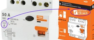
The installation standards for RCDs must take into account I∆n - this icon on the body means the leakage current, the value at which tripping and de-energizing occurs. Example of part of the range: 6, 30, 100, 500 mA. Sometimes it is displayed in Amperes (A), then it must be divided by 1000: 0.006 and so on. The “non-release” phenomenon, when it is impossible to tear your hands away during a current injury, appears at 30 mA, therefore, for household equipment and structures with which people come into contact, products are selected that trip at 10 mA or up to 30 mA of leakage current.
For powerful equipment, such as boilers 1...3.5 kW and above, for wet conditions (“wet” auto-protection) always take I∆n 10 mA.
But if, in addition to the high-power consumer, there are other devices on the line (their powers are taken into account together), then with 10 mA leakage there is a risk of false alarms, therefore in such situations they choose I∆n 30 mA (SP 31-110 clause A.4.15).
Trip occurs within 50–100% of the diphtoc setting. A product with I∆n 30 mA will open contacts at 15–30 mA. When protecting double or with several levels according to SP 31-110 clause A.4.2 for a device located closer to the power point (input), it is recommended that the setting and response speed (selectivity) be three times higher than near the equipment being serviced.
How does an RCD work?
RCDs have found application in both single-phase residential networks and three-phase industrial networks. It is designed to turn off the power supply in 2 cases:
- The person touched a live part. The protective device prevents electric shock.
- Damage to wiring insulation and contact of live parts with the ground or body of an electrical apparatus. For example, a washing machine, water heater or refrigerator.
The principle of operation of an RCD
The operation of an RCD is based on a comparison of currents flowing through the phase and neutral conductors. If they are equal, everything is fine. The apartment is under voltage. If you touch a phase wire, part of the current will flow into the ground through the human body. This will create a difference between the currents flowing through the L and N conductors at the entrance to the apartment. The RCD is triggered if differences appear.
RCD has proven itself as a fire-fighting agent. One of the causes of wiring fires is current flowing through damaged insulation to ground. At the point of breakdown, heat is released, leading to ignition of the cable. If an RCD is installed in the apartment, this situation is almost impossible. When an insulation breakdown and a ground fault occurs, the device will detect the current difference and turn off the system.
Important! It is necessary to distinguish between a circuit breaker, an RCD and a difavtomat. These protection devices have a similar appearance but perform different tasks. The circuit breaker protects the wiring from short circuits and overloads. The RCD serves for human safety. It will turn off the voltage if you touch a live part. The difavtomat combines the functionality of both devices. Protects a person from electric shock and protects wiring from short circuits.
How to choose and not make a mistake
Regardless of the purpose, devices are selected according to the following parameters:
- Load capacity. For a device, the amount of current that its power contacts are designed for is important. At nominal value they are most often used at 16A, 25A, 32A, 40A, 63A, 80A.
- Leak detection method. According to the type of leak detection, they are divided into electronic, in which the leak is determined by an electronic key, and electromagnetic, in which the leak value is taken from the magnetic core. Electronic ones are more affordable, but have disadvantages in the form of failure to operate when one of the phases fails.
- Sensitivity to leakage current. Sensitivity determines the device's ability to trigger. The most sensitive devices for 10 mA leakage current. But their use is limited by the number of consumers due to possible false alarms and the presence of natural leakage currents.
- Circuit current type. Based on the type of current, they are divided into those triggered by alternating current and pulsating current.
Based on the number of connected phases, they are divided into two-pole and four-pole. Single-pole for a 220 V network, three-pole for 380 V. In houses and private households, due to the use of a single-phase network, single-pole RCDs are used.
To select a protection device, it is necessary to determine its purpose. By purpose they can be divided into the following types:
- Household ones are single-pole RCDs of low sensitivity with a load current of no more than 50 A. Such requirements are due to the large number of household appliances and the associated large natural leakage points. Very sensitive ones will constantly trigger false alarms. A load current of 50 A is determined by the parameters of electricity meters installed in residential premises, which do not exceed this rating.
- For industrial applications - sensitive four-pole RCDs with high current ratings. These requirements are due to the high current consumption of industrial equipment, the use of a three-phase network and increased requirements for its protection due to its increased danger and high cost.
- Specialized. Specialized ones include fire-fighting type B. They are highly sensitive not only to AC leaks, but also to minor DC ripples.
Electronic RCDs are more affordable, but have operational drawbacks such as failure to operate when one of the phases fails
Answers to frequently asked questions
- Where in the house should a protective device be installed? Only indoors, away from the bathroom and kitchen.
- They recommend that I buy an RCD on the radio market, it’s cheaper there. How long will they work? Purchasing such devices is unsafe because... dubious devices are not certified, and no one guarantees the quality of their work.
- Usually conductors are connected to terminals regardless of phase, why look for zero? Complex devices, such as automatic machines, include additional components for which phasing is important.
- Is it possible to connect several sockets to one RCD? Yes, only in parallel connection.
- How will several connected sockets affect the operation of the device? No way. The response time is the same.
RCD or differential circuit breaker?
The residual current device does not have overcurrent protection. Therefore, when a short circuit occurs, there is a possibility of its damage - contact burnout, failure of the differential transformer. To do this, one or more automatic machines are installed in the circuit. In them, the current is switched off due to the operation of a release - thermal or electromagnetic.
The machines operate in two modes - overload or short circuit, when the current values significantly exceed the rated one. When overloaded, this occurs relatively slowly, which is why thermal bimetallic plates are used. During a short circuit, the current increases quickly, so the design includes a solenoid with a moving core.
Advantages and features of RCD:
- Protecting people from electric shock.
- Possibility to select a model based on installation parameters, supply voltage, shutdown mechanism and response time, and current application.
- Maintainability.
- The cost will not greatly affect the budget for creating an electrical network.
- Integration into a finished wiring diagram without significant changes.
A differential machine combines the functions of an RCD and a conventional machine. All components are located in one housing. But when designing complex branched electrical networks, their use is impractical, since several circuit breakers can be connected to one residual current device at once.
Selectivity
RCDs with a selectivity function differ from ordinary ones in that they have a certain time delay. They are used when several devices are mounted in one distribution panel at once. In order for the entire chain to work smoothly, it is imperative to adjust the response time settings. According to this characteristic, there are two types of RCDs: “G” and “S”.
Visually about the RCD selectivity in the video:
An ordinary RCD is triggered 0.02-0.03 s after detecting a current leak, a type “G” device is triggered after 0.06-0.08 s. RCD type “S” has the longest time delay of 0.15-0.5 s.
The protective shutdown device on the outgoing lines is mounted without a time delay, and is installed at the input of type “S” or “G”. As soon as a current leak appears on any consumer line, the group RCD instantly reacts and turns off.
If it is not working properly or for some other reason does not work, then after a specified time the input device will turn off.
Selectivity can be ensured not only by time, but also by current.
What are called difavtomats?
Differential automatic machines are, in fact, also a type of RCD. It just turns out that these are two devices in one, since the mechanism is capable of controlling both current leakage and voltage .
The differential machine consists of a switch and a machine
On the body of this device you can notice the presence of special markings that not only indicate the rated current, but also the maximum value that it can withstand. However, the mechanism will work at a lower rated current.
It turns out that this is an improved device that replaces the automatic machine and the standard version of the RCD. The difference is that such a mechanism has a higher cost .
Safety regulations
Device current parameters
In household electrical networks, differential circuit breakers of the C16 type are most often used, while others are not popular. In lighting circuits, devices with a rated leakage current of up to 30 mA are used. If there are single chains, use difavtomat - 10 mA. Protection for input circuit breakers assumes a rated leakage current of up to 300 mA.
It turns out that most energy consumers use more energy at the moment of start-up, and not during operation. Such currents are considered to be starting currents, which exceed operating currents.
In order to ensure that the power supply does not stop when a high-power electric motor is turned on, the difavtomat operates in such a way that shutdown occurs only when the rated current increases several times.
According to the current parameters at which the protection is triggered, the machines are divided into the following types:
- B – withstands load up to five times;
- C – withstands load up to ten times;
- D – power is turned off when the rated current increases up to twenty times.
If the network has a certain number of consumers with minimal capacity, then it is better to install a type “B” device. In an average apartment or private house, a type “C” device is connected. In industrial facilities where powerful equipment is available, type “D” devices are installed.
Connecting an RCD in a two-phase network
Two-phase power refers to non-standard connections, where a converted old-style 127 V transformer was reconnected into a triangle for modern 220 V consumers, which are powered by linear voltage from it.
Connecting an RCD in a two-phase system
To connect a residual current device to a two-phase circuit, it is necessary to disconnect both wires at the input to the panel, since each of them is under potential. Then each of the phases is connected to the corresponding phase terminals and neutral terminals, further observing their polarity. Unlike a single-phase system, circuit breakers at the output of the RCD must be installed for each line, or they can be replaced with one two-pole one.
Some tips for choosing
And some recommendations on choosing an RCD. If you plan to install one device at the input, then choose high-quality products from well-established manufacturers. These are companies such as:
- "ABB";
- "Legrand"
- Schneider Electric.
Residual current devices from these manufacturers will cost you about 1800-2000 rubles.
If you want to connect several RCDs and circuit breakers in an apartment (for each outgoing branch), then you will either have to spend a lot of money or choose devices that are a little cheaper. In case of small financial possibilities, opt for RCD or “EKF”, they are slightly inferior in terms of quality and reliability, but also cost much less (about 600-700 rubles).
We have given several options for how to connect an RCD. Choose the one that is most suitable for you, depending on where you live (in an apartment or a private house), what kind of network you have (single-phase or three-phase). Well, decide how many devices you will supply (one at the input or for each consumer group), based on your financial situation.
Protection in three-phase network
To distribute the load in systems where the total electricity consumption exceeds 10 kW, three-phase networks are used. They have three phase wires, in each the phase of the alternating current is shifted by 120° relative to the neighboring one. The current returns through one neutral wire.
For such a network, special protection devices are used, designed for connection to a three-phase network. Their switching with individual elements is more complicated than connecting for a single-phase network. But this way you can ensure stable operation of the electrical network with heavy loads on individual lines.
General protection device and group RCDs
To organize the circuit, you need a three-phase model and single-phase ones for installation in each power supply line. A central machine with four poles is mounted; single-pole ones are used for individual networks. A feature of an overload or short circuit in a three-phase network is sudden heating and the likelihood of a fire in the wiring.
Recommendations for organizing power supply:
- use of ignition-resistant cable (VVGng, PPGng(A)-HF, PPGng(A)-FRHF);
- for each phase there is a wire with individual color marking (black, red, gray);
- installation of several RCDs and one common one increases the level of protection against leakage currents.
A similar connection for a three-phase network is used in private houses with electric heating, in industrial and commercial buildings.
Circuit with counter
The meter is connected according to the standard scheme - it is located between the main circuit breaker and the protective device. The meter must be three-phase. This technique is advisable if one or more circuits are designed for high power consumption.
Otherwise, you can choose one of the options - installing a common RCD or for each circuit. This will slightly reduce the degree of protection, but will reduce the cost of organizing power supply.
Connect without grounding
How to properly connect an RCD
Connecting an RCD in the absence of grounding is done quite often in many apartments and old houses. Since in old-style houses there are usually power cables with one phase and zero, it is not possible to connect grounding. To make grounding, you will need to install a grounding protective loop around the perimeter of the building, and be sure to change all the wiring in order to place a new cable with “ground”. Only connecting such a core to a special conductor for sockets or individual contacts on powerful household appliances will allow grounding to be done in an apartment or private house. By combining such protective measures together with an RCD and a circuit breaker, it is possible to provide a residential building with all the necessary measures to prevent accidents.
However, many people simply do not have the opportunity to replace all the wiring in the apartment, since today this is an expensive update. For this reason, an RCD without grounding is installed. Despite the fact that the electrical network is not grounded, you should not ignore the connection of the residual current device. The protective equipment itself does not have terminals for the grounding conductor. It has places for connecting a phase and a working zero. Since this device has a completely different purpose, there is no need to make separate grounding points for it.
Connection diagram for a two-pole RCD
A connected RCD in the absence of grounding is expected to cut off the supply of electricity to the network when the potentials of the incoming and outgoing current change. Therefore, if there is no grounding structure in the house and a three-wire wire is not installed, there is also no reason to refuse to connect other types of protective equipment. It is advisable to simultaneously install a residual current device and a circuit breaker. The latter device will prevent short circuits in an apartment or private house if the cable is damaged, as well as prevent burnout of household appliances during voltage surges in the electrical network. An RCD cannot protect or warn against such things. It is designed to prevent AC leakage in the circuit.
According to the Electrical Installation Rules (PUE), you cannot use RCDs that react to differential current in three-phase circuits with four wires (the grounding is combined with the working zero). If you install a residual current device on the entire electrical network, then this circuit will be simpler. When connecting an RCD without grounding, you must know the parameters of the power cable that is laid in a private house or apartment, as well as the total current value, when calculating the simultaneous connection of all household appliances to the network.
Typically, the installation diagram of protective equipment provides for sequential connection of all elements. Even if changes are made to the new circuit by adding a new source or element, the sequence should not be broken. In this case, it will simply be connected to the appropriate section of the electrical circuit. For single-phase electrical wiring in which there is no grounding conductor, the residual current device must be placed in front of the distribution panel and in front of the energy supply meter. Then there are circuit breakers (if there is more than one) and a voltage equalizer. If you follow this scheme, you can exercise full control of all the wiring in the house, and not just its individual branch.
For individual branches with powerful electrical equipment, circuit breakers are installed that will respond to high voltage without turning off the power supply throughout the house. The most common scheme for connecting an RCD is the one designed for a single-phase power cable with a voltage of 220 volts. If the owners want to install less powerful protective equipment on each line with powerful equipment, then such a scheme will have a slightly different look. It is recommended to make connections separately for the bathroom, garage or workshop, basement, and also for the kitchen. There are often large studio kitchens where quite a lot of electrical appliances are connected to the circuit at the same time. In such a situation, it is advisable to divide the residential building and adjacent premises into separate areas with electricity consumption, providing each with independent protection.
Installation location
Typically, the installation location of the RCD is in the electrical panel. It contains various devices for metering and distributing electrical energy of voltage up to 1000 V. In the electrical panel, along with the RCD, there are automatic circuit breakers, an electric meter, distribution terminal blocks, and other electrical devices.
If you have an installed electrical panel, then to install the residual current device you will need a minimum set of electricians. It will include pliers, side cutters, a set of screwdrivers, and a marker.
In rare cases, you may need a set of socket wrenches and an electrical tester. The RCD is installed on a DIN block. If there is no space on the existing block, you will need to install an additional one.
Connection instructions
Installation of a residual current device is carried out only after calculating its characteristics and developing the general electrical circuit of the room. Can be installed in a central electrical panel or in a separate cabinet. Before work, the integrity of the model and the possibility of placing all safety elements are checked.
Installation procedure:
- Power outage, check with a multimeter, indicator screwdriver.
- DIN rail installation. It will record all elements of the protective system.
- Installation is done immediately after the meter, but before the main input machine. This is necessary for short circuit protection.
- The connection of incoming wires (phase, zero) is carried out to the upper contacts. Designations – L (phase), N (zero). The outputs are connected in the same sequence. Polarity must be observed.
- The mounting screws are tightened until they stop.
- Functionality is checked. There is a button on the instrument panel, pressing which simulates leakage current. If after pressing it the switch works, everything works fine.
Another way to check is with an incandescent lamp. The phase and neutral wires are connected to the base, current leakage occurs.
Types of electrical networks
The power supply to our apartments and houses comes from a single-phase or three-phase network.
Single-phase electrical power is one phase and zero. To power household appliances and lighting devices, you need phase voltage, which is obtained at the output after the step-down transformer. This single-phase power supply involves powering from one phase of the line.
Electric current moves through the phase conductor, and through the neutral conductor it returns to the ground. Most often, this type of electrical wiring is used in an apartment, and it has two varieties:
- Single-phase two-wire network (without ground). This type of electrical network can most often be found in old houses; it does not provide for grounding of electrical appliances. The circuit includes only a neutral wire, marked N, and one phase conductor, which is designated L.
- Single-phase three-wire network. In addition to the neutral and phase conductors, it also contains a protective grounding conductor, designated PE. The housings of electrical devices must be connected to grounding conductors; this will protect the equipment itself from burnout, and people from the action of electric current.
The house often contains equipment that requires three-phase voltage (pumps, motors, if there are machines in the barn or garage). In this case, the network will consist of neutral and three phase wires (L1, L2, L3).
Similarly, a three-phase network can be four-wire or five-wire (when there is also a protective grounding conductor).
We have decided on the types of networks, and now we will move directly to the question: is it possible to connect an RCD without grounding and how to properly install this device?
Is it possible to connect an RCD without grounding - on video:
How to properly connect machines and RCDs
Before starting work on connecting the machines, it is necessary to prepare all the devices:
- Mounting rail (sometimes it is already included with the finished shield). In other cases, you will need to measure the required length yourself and cut it with metal scissors.
- Screwdriver.
- Wire cutters.
- Wire stripper.
Connecting machines and RCDs - step-by-step instructions
Step 1. To begin, you should attach two buses to a metal DIN rail: neutral and ground. This is easy to do; you just need to insert them at one end and then snap them into place.
This is what the tires should look like after installation.
Step 2. Now you need to secure the machines in series. At the bottom they have a special latch, which you just need to pull down and then secure the machine to the rail.
Each machine must be secured to the rail one by one.
Step 3. Next you need to take a three-core cable. As a rule, the ground wire is yellow, the neutral is blue, and the phase is white or pink (as in our case).
It is important not to mix up the power cable wires
Step 4. First we need to connect the neutral wire to the neutral bus. This is easy to do - you just need to unscrew the bolt with a screwdriver.
There is a hole for cables of different sections
Step 5. Now you need to connect the yellow ground wire to the ground bus.
This is done in the same way as in the previous version.
Step 6. The next step is to secure the power wire (pink). Contrary to many opinions, it should always come from the top. You should connect the wire, but you shouldn’t tighten it right away - the reason is that you will then have to supply the power wire to all other machines.
In this step, the wiring is connected “live”
Step 7. Seventh: you need to insert the power wire into the upper machine, and then insert one end of the additional jumper into the same hole.
Now you need to insert the jumper into the adjacent machine, and then into the other, alternately tightening the screws
Step 8. Now you need to pay attention to the last differential machine. On its body, as a rule, there is a connection diagram.
The first input here will be designated by the letter N - this will be zero, the second input will be designated as I (L) - this will be the phase.
Step 9. Now it has become clear that the phase is at the second input, which means that the other end of the yellow jumper wire should be secured there. We tighten the screw by analogy with the previous options.
Thus, we have completed connecting the power cable that comes from the shield
Step 10. Now you need to connect the wires that come from the room. First, you will need to remove the insulation layer from their ends. A special tool is used to strip the ends of the wires.
Here you can turn the screw and set the wire thickness
Step 11. Here you should also connect the neutral wire to the corresponding bus.
You can unscrew any loose bolt
Step 12: Now you need to secure the ground wire again.
The wire must be tightened carefully, without catching the insulation layer.
Step 13. Now from below we fix the power wire that comes from the electrical device.
The following wiring, by the same analogy, will be connected only from below
Step 14. Now you need to take an additional wire, connect it to the zero bus, and then to the first input on the differential machine.
We fix the wire in the first hole of the difavtomat
Note! Wiring to electrical appliances will go from the lower hole in the automatic machine.
How to properly connect wiring to machines
There are a large number of devices that will make it easier to connect contacts to automation. In order to choose the appropriate option, we will consider them in detail.
Flexible wire lugs
In order to connect elements of an electrical panel, flexible wires with many wires are often used, because even a beginner can cope with connecting such contacts. But there is a nuance here too.
As we have already discussed above, many craftsmen fix the wire with a clamp without termination , which is why the fragile wires begin to break off and the contact weakens .
If stranded wire is used during installation, then do not forget about the lugs
double tips were invented for this purpose . They are best suited when you have to install a lot of jumpers.
Special tip for forming bridges
Arched bend
Usually, to connect the conductors to the clamps, it is necessary to remove 10 millimeters of the insulating layer - this is enough to form an arc on the messenger, which is then placed in the terminal. As practice shows, most electricians, in the absence of tips, use this method.
As a result, it is possible to obtain reliable contact that will not weaken over time. This method is suitable if there is a monolithic core at the end.
Thanks to this connection, the area of interaction between the contact and the clamp expands, this will avoid problems with the operation of the machine
Unbreakable jumpers
When you have to connect several machines with one wire, it becomes necessary to use a comb (bus) . However, it is not always at hand, so you can form a homemade comb from wire of any cross-section.
You should bend the wire so that you get a comb. Then, at the bend site, you need to strip the wires.
Method for forming a continuous comb
Connection errors
During the drawing up of the diagram or installation, errors may appear that lead to the incorrect functioning of the system or its complete inoperability. These can be avoided until the final start-up, when most of the wires are hidden and the devices are installed.
Common connection errors:
- Rated current value
. It must be equal to or higher than that of the input machine. - Poor polarity
. The input and output zero and phase are incorrectly connected. - Incorrect grouping
of each electrical network. Zero is connected to another line or is a common circuit for everyone. Leads to false protection activation. - Installation of sockets
. When connecting the neutral and connecting wires, false triggering of the RCD will occur in them when a load occurs. - Extra jumpers
, combining neutral wires between two devices.
To check the correct operation, you need to use the “Test” button, as well as simulating the appearance of a leakage current. This is done before the final installation of the system in order to correct possible errors.
Circuit assembly
There are no difficulties in practical implementation. The entire algorithm will look like this:
- All work with electricity always begins with de-energizing the workplace. Therefore, turn off the apartment input machine. Using an indicator screwdriver, make sure that there is really no voltage at its output.
- Attach the residual current device to the DIN rail. On the back side there are latches that must be inserted into the perforated holes on the rail.
- The body of the residual current device is marked with input and output contacts for neutral and phase conductors. Power is supplied to the RCD from above, and the load is connected from below. From the output terminal of the circuit breaker, connect the phase conductor “L” to the corresponding input terminal of the RCD. Make similar connections with the neutral wire “N”.
- Distribute the phase output from the RCD among all outgoing line machines.
- Connect the output from the zero contact to the zero bus. And from there the conductors will disperse to consumers. After the RCD, the neutral conductors are not combined into one node; this will cause false alarms of the device.
- After completing all the switching, turn on the input machine. Check the correct connection and operation of the residual current device. For this purpose, there is a special “TEST” button on the RCD body. Its main goal is to simulate current leakage. From the phase conductor, current is supplied to the resistance, and from it, bypassing the transformer, to the neutral conductor. Due to the resistance, the current at the output has become less and, due to the resulting imbalance, the shutdown mechanism will operate. Press the test button, the RCD should turn off. If this does not happen, it means that there are inaccuracies in the connection or the device is not working properly.
Common mistakes when connecting an RCD on video:
If you connect an RCD with grounding, remember that it is unacceptable to use water pipes or other communication structures for this purpose.
Grounding must be done correctly, and not done independently, only in this case can you be completely confident in safety. If the grounding is not working, then be sure to disconnect and insulate the conductors coming into the electrical panel.
Safety regulations
If you decide to connect the RCD yourself, the success and safety of the work performed will depend on your compliance with the safety rules:
- Before starting installation operations, be sure to remove the voltage from the area (after disconnecting it would be a good idea to check the presence of potential with an indicator);
- Take care of the marking of the wires - this will make it much more convenient to connect the device so as not to confuse the leads;
- Be sure to use factory terminals and clamps, and never allow twisting, soldering or other connections with poor contact;
- After installation, check the reliability of the connections and the presence of sufficient insulation on all current-carrying elements;
- When commissioning, be sure to check the functionality by pressing the test button;
- When you first apply voltage to a newly installed device, it may fly apart due to manufacturing defects or installation defects, so it is better not to stand nearby or take measures to protect your eyes.
Before applying voltage after completing installation, be sure to ensure that no one in your household or colleagues touches live elements.