According to the rules for designing electrical installations and fire safety standards, the electrical network at the entrance to an apartment or cottage must have a fire protection RCD. This is a regular differential switch, only it has a higher leakage current value than classic electric shock protection devices.
When choosing such a device designed to prevent fire, a number of conditions must be met. Its installation also requires compliance with specific electrical installation requirements.
Let's look at the operating features of this device, its scope of application and the key features that you need to pay attention to when choosing this equipment.
General functions of differential switch
In household and industrial electrical networks, several types of protective devices are used to prevent fires and electric shock to people. All of them are designed to be triggered in the event of breakdowns in electrical installations or breakdown of wiring insulation.
The principle of operation, the elements inside and the controlled characteristics are different. However, the task is the same everywhere - if problems arise, quickly break the power supply chain.
You should not confuse RCD and difavtomat; their design and functionality are different. The first device exclusively monitors the occurrence of leakage current, and the second is also designed to operate in the event of short circuits and overloads in the network
RCD (differential switch) is an electrical device that breaks the power supply line when a high leakage current occurs. The latter occurs when the insulating layer in various thermal electric heaters and wires breaks down.
If at this moment a person touches the body of the broken equipment, then the electric current will flow through it into the ground. And this is fraught with serious injuries. To prevent this from happening, a residual current device (residual current circuit breaker) is installed in the circuit.
The RCD consists of a regular and a fire protection device consisting of:
- housings;
- transformer with three windings;
- EMF relay.
In normal operating condition, the electric current passing through the transformer windings forms magnetic fluxes with different poles. Moreover, when they are added, the final result is zero. The relay in this state is in the closed state and passes current.
But when a leak occurs, the balance on the windings is disrupted. The automatic switch in question reacts to this by opening the circuit. As a result, the voltage in the network disappears - the broken electrical appliance is de-energized, and the person is no longer in danger. The RCD is triggered literally in a few milliseconds.
Electrical equipment becomes a source of fire when:
- short circuits;
- overloads in the network and/or the electrical installation itself;
- excess leaks associated with insulation degradation.
In the first two cases, protective shutdown is carried out using a difavtomat (thermal electromagnetic release) or by blowing a fuse. For the third situation, there is precisely the RCD under consideration for differential current. There are also special insulation monitoring devices, but they are expensive and are rarely installed in apartment or house panels.
Standards
As mentioned above, the requirements for RCDs are given in various GOSTs. The package of documentation related to RCD-D covers AC devices used in protection against electric shock and the negative consequences of leakage with voltages up to 440 V and power up to 200 A. Among these documents:
- GOST R 50807-95 - classifies, lists the characteristics of RCDs and contains testing measures and methods;
- GOST R 30331.3 - defines the rules of application.
The standards are similar to internationally accepted ones and contain all the necessary information. Note that GOST R 50807-95 classifies only mechanical electrical switching devices/complexes as RCD-D.
How can an RCD prevent a fire?
In case of electrical injuries, sparks that can cause a fire are not generated. But a fire can still occur if a leakage current occurs. It's a matter of wiring and electrical current passing through the cables. Initially, the cores are designed for strictly defined voltage values. If these parameters go beyond the design standards, then it won’t be long before an open fire appears.
If a powerful leakage of electric current begins through the broken insulation, then the metal of the wires, which is not designed for this, begins to heat up too much - this leads to the melting of the insulating braid and heating of surrounding objects
The task of the fire protection RCD is to control this situation and prevent overheating of the wiring. If the insulation is damaged and a leakage current has formed, the protective device simply disconnects the problem line from the network. If there is a differential switch in the circuit, the metal cores heat up too much and a fire does not even occur.
The leakage current in the range of 300–500 mA and a voltage of 220 V is the heat generated, equal to the heat generated from a lit household lighter. Such heat generation inevitably leads to ignition of the wiring and everything nearby.
The main function of the class of RCD under consideration is not human protection, but increased fire safety. To prevent electric shock, conventional devices with a lower leakage current rating are placed in the circuit after fire protection devices.
Functionally, the fire protection RCD protects:
- Input cable in front of you.
- Wiring the consumer line after yourself.
- Connected electrical equipment when the standard differential switch located below does not operate in the event of a fault.
The fire protection RCD is part of the cascade protection of the 220 V electrical network. It is not used in smoke and fire monitoring systems. On the contrary, such protective devices should not be present in them. Under certain circumstances, they can disable such a control system, which is completely unacceptable.
Description of the device and its types
All models on the market today are designed for installation in a load control cabinet or on an electrical panel equipped with a DIN rail. RCDs are divided into several types, depending on the type of protection required. The figure below shows the symbols on the RCD body.
By type of current there are:
- Type “AC” - they can disconnect the circuit both when an instantaneous leak occurs and when it gradually increases.
- Type “A” is similar to the previous one, but differs in the presence of a node that controls direct current, which is why its cost is much higher.
- Type “B” is capable of detecting leakage of both direct and alternating currents, as well as rectified ones, due to which it is used in manufacturing enterprises, but for domestic needs it is impractical due to its high cost. If protection is required in the circuit of a private house or apartment, in the case of the operation of expensive devices and equipment, many manufacturers recommend installing an RCD of type “A”.
Based on the response time delay, the following are distinguished:
According to the operating principle, there are electromechanical and electronic:
- The first ones are triggered by the leakage current itself
- The latter have an electronic circuit and require an additional power source for their operation.
Based on the number of poles, RCDs are divided into:
- Two-pole (single-phase).
- Four-pole (three-phase).
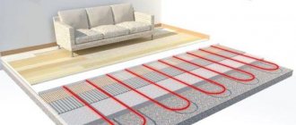
Equipment selection criteria
Existing RCDs are divided into single-phase and three-phase. Only the first devices are used in everyday life. A single-phase line almost always goes to an apartment or a private house from the electrical panel. For this purpose, a differential switch is used with two terminals (input plus output), whereas three-phase analogues have four terminals for wires.
All RCDs are divided according to the type of leakage current into three groups: “A”, “B” and “AC”. For fire-fighting needs, you should take the “AC” option (only for alternating current), “A” and “B” are more expensive, as they are additionally designed to work with pulsating and rectified currents
Residual current devices are:
- electronic;
- electromechanical.
The former are more expensive, but less reliable. In almost all cases, it is best to take a fire protection RCD of the electromechanical class. This switch does not require external power. If the supply line breaks, the electronic analog stops working and monitors for insulation damage. Plus, during a power surge, its response time increases.
The two main criteria for choosing a fire RCD are the selectivity of the device (the ability to set a shutdown delay) and the high leakage current parameter (100–300 mA). If one of these conditions is not met, then the system of protective devices in the electrical panel will not work as expected.
A selective type RCD is marked on the body with the letter “S”; it is the one that needs to be installed as a fire protection element of the cascade (it switches off with a set time delay)
According to the standards, a fire protection RCD must differ at least three times in a larger direction from the downstream conventional one in:
- leakage current;
- response time.
If the difference in these parameters is less than three times, then when the downstream differential switch is triggered, the fire protection device will also react to disconnect the circuit. As a result, it will be more difficult to find out the cause of the shutdown, and all consumers in parallel lines that have no problems will be left without power.
Ideally, a cascade circuit of various RCDs should work so that when problems arise, only the device that is located closest to the location of the insulation breakdown reacts. In this situation, only the protected circuit is switched off. The rest remain under tension.
With the requirement of a high leakage current parameter, the situation is as follows. For conventional RCDs it is selected within the range of 10–40 milliamps. The operating electric current (maximum consumption by electrical appliances connected to the line) in this case reaches 16–40 A. For lighting and sockets with household appliances, this is quite enough.
However, in any electrical network there are natural leaks. In the project of an intra-apartment or intra-house energy system, they are specially calculated in order to correctly select the RCD. They should not exceed 1/3 of the leakage current of the selected differential switch for a particular line. Otherwise, the protective device will trigger falsely on a regular basis.
According to the rules, a fire protection RCD is installed immediately after the electric meter at the entrance to the house; it sums up the natural electrical leakages from all household appliances connected to the home
If the protective device is selected, as for the usual case, at 10–40 mA, then the power supply will be permanently disconnected. In fact, the RCD will continuously detect leaks, triggering a power shutdown in all power supply lines of the house.
Connecting an RCD with grounding
Depending on the configuration of the electrical network in which the RCD will be installed, the device itself should be selected. It is important to pay attention to the presence of a PE conductor in the circuit (a separate protective conductor intended for protective grounding of the electrical circuit). This type of wire is present to a greater extent in new buildings. In buildings built during the Soviet Union, the PEN scheme was used, in which the protective conductor was combined with the neutral wire. The installation option with grounding is more preferable, since the protection of people and electrical appliances in this case will be more effective - the circuit will be disconnected immediately at the moment of current leakage. The connection diagram is shown below:
Whereas when connecting an RCD in a network with a PEN circuit, disconnection will occur only upon contact with a dangerous device.
Before direct installation, you should find out what type of grounding is used in the circuit. If the neutral of the power supply is solidly grounded, then such a circuit is called TN. One of the varieties of such a circuit is TN-C - this is a circuit in which the zero working and zero protective conductors are combined in a single wire throughout the entire circuit. This is the most common scheme due to its simplicity and low cost. But this scheme also has its drawback - if the PEN conductor breaks, and the body of the electrical device has its own grounding, then the use of such a device will become dangerous, since all the potential will be transferred to the body, and a voltage will arise on it equal to the voltage in electrical circuit.
“Some electricians, due to inexperience, use a jumper between the neutral and the ground terminal in the socket - this is also incorrect and can lead to electric shock, even if a protective device is installed in the circuit. If the PEN wire breaks, the RCD will not work, and voltage will appear on the housing of electrical devices, which can lead to damage. In this case, only an accident can save a person - if, at the moment of touching the body of the device, he also comes into contact with a grounding loop, such as a water pipe or heating system.”
When connecting an RCD, the TN-S scheme is also used, in which the neutral protective conductor is connected separately, and its connection with the neutral occurs only in the power source, which provides maximum protection for electrical appliances and virtually eliminates the possibility of electric shock to humans. With this scheme, even if one of the wires (N or PE) breaks, the devices in the circuit will continue to function, and no voltage will appear on their cases, since the potential will transfer to the remaining wire. Even if both wires break, the circuit and devices will remain safe for humans; in this case, a blackout will simply occur.
Safety switch installation diagrams
The RCD is not designed to monitor overloads in the electrical network, so it must be installed together with a standard “machine” - a circuit breaker. This way the protection will be complete in all problematic areas.
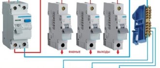
The standard diagram for connecting protective devices in an electrical panel is as follows:
- The first machine at the entrance is a machine.
- Then an electricity meter is installed.
- Then a fire protection RCD is connected (100–300 mA).
- Afterwards, the circuit is divided into several separate consumption lines with an RCD against electric shock (10–40 mA).
In some schemes, the first circuit breaker is replaced with a packet switch, and less powerful circuit breakers are then installed on consumer lines. This option also does not contradict the rules.
Image gallery
Photo from
General diagram for connecting a single-phase RCD
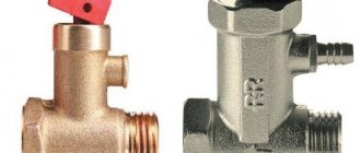
Differences between fire and conventional RCDs
Differential current switch and automatic circuit breaker
Installation of protective devices in different electrical networks
When connecting wires, it is important to ensure that the outputs from the RCD are not combined at a common zero and do not intersect anywhere with other neutral conductors or the panel body. After this protective device, the line should immediately go to another RCD or circuit breaker, and then directly to consumers.
After installation is completed, it is necessary to check the correct assembly of the entire circuit and the functionality of the protective device.
First, some equipment is plugged into the outlet to create a load in the network and voltage is applied. If everything is correct and the insulation is intact everywhere, then no RCD trips should occur
Then the differential switch itself is checked. To do this, most RCDs have a “T” (“TEST”) button. When it is pressed, the calculated leakage current is simulated, as a result of which the protection should operate normally. Moreover, testing should work regardless of whether there is a load or not.
If when you press “TEST” the RCD does not disconnect the line, then it is faulty. It is possible that the leakage simulation circuit is broken. In this case, the protection device will continue to perform its functions as intended. However, even such a switch is better to be replaced immediately. It is recommended to carry out such a check once a month.
RCD parameters
By what main parameters is the RCD characterized? The two most important of them are:
- ⚡
rated differential breaking current (or leakage current) - ⚡
rated load current
In 220-380V home electrical wiring networks, in order to protect a person from the effects of electric current, an RCD with sensitivity or differential is used. shutdown current 10mA and 30mA. In order to protect against fire, you need to choose an RCD with a sensitivity of 100mA or more.
If you have only one or two groups of electrical wiring at home, you can install one RCD with a current of 30 mA.
It will play the role of both fire protection and will be able to protect you from electric shock.
Why is it needed?
Installation of such devices is necessary for several reasons. Mainly, it was designed for protection. From what? Firstly, the RCD protects people from electric shock, especially in cases where there are faults in the electrical installation. Secondly, the device is triggered and cuts off the current due to accidental or erroneous contact with live parts of the electrical installation, in case a current leak occurs. And thirdly, it prevents the electrical wiring from igniting in the event of a short circuit. As can be seen from the above, this machine actually performs a very important function.
RCD
Today you can find differential circuit breakers, the peculiarity of which is to combine a circuit breaker and an RCD. Their advantage is that they take up less space in the shield. In all cases, when connecting, all contact connections must be connected to it not from below, but only from above. One reason is that it is more aesthetically pleasing. But there is a much more compelling reason. The fact is that an RCD can reduce the efficiency of all household items. Moreover, during repair work, the electrician will not get confused, and he will not have to study complex, confusing diagrams. So now it's time to look at your connection options.
Connection features
It is very important to know that when connecting a residual current device, the grounding cable is not connected to it. Many people who do not have special knowledge in the field of electrical engineering believe that the protective zero must be connected to all contacts of equipment connected to the electrical network
This opinion is wrong. If you short the ground to the working neutral conductor, the device will malfunction.
When connecting the contacts of the power cable to the RCD, you must carefully ensure that the polarity is strictly observed (otherwise it will not work). The phase wire must be connected to the corresponding socket on the device, as well as “zero”. To distinguish them from each other, you should pay attention to the colors of the outer braid of each core. Color and markings allow you to find out what purpose a particular wire has. The phase is usually red, sometimes brown or white. The working neutral conductor is blue or light blue, and the protective neutral conductor is yellow, green or yellow-green (longitudinal stripes along the braid).
On the equipment body you can see symbols that determine what type of wire needs to be connected to it. For the phase - “L”, and for the zero working core - “N”. Typically, the energy supply meter is connected to the upper terminals, and the load cables are connected to the lower points, respectively. In a diagram that takes into account the connection of circuit breakers, the polarity must also be observed - phase to phase, and zero to neutral. If the system does not have a grounding conductor, then only two wires need to be connected to the distribution panel.
If the polarity is observed correctly, the device should operate stably and respond quickly to changes in potentials in the network. Of course, all work with electrical engineering must be carried out with a de-energized electrical line. During installation work, it is necessary to comply with safety regulations, as well as comply with fire safety standards. It is also necessary to take into account the rules of the PUE. To provide the RCD with reliable protection from moisture, gases, fire, dust and other external factors, it is placed in the housing of the distribution panel. It is made from sustainable materials. If used correctly, the device will last quite a long time.