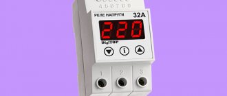
Specifications
Underneath there is indeed a diode bridge, which is mounted in a hinged manner, and a varistor to limit voltage surges at the contactor input and coil protection. ESB is a series.
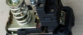
Connection diagram for ABB esb 20-20 contactor for 220V via a switch
Well, in fact, contactors of common series have a bunch of bells and whistles.
And the second contactor is completely de-energized, and the red-green lamp goes out, indicating that the non-priority is not working AT ALL. EN series contactors. The contactor is modular. The number of pairs of power contacts for ABB magnetic starters is even, either two or four. Here I was somewhat surprised, but perhaps it comes from my ignorance of this series. Now new contactors are slowly starting to be supported in warehouses.
Each symbol in the name of ABB contactors has a specific meaning. The reverse procedure awaits you when you return; by pressing the switch key, you turn on all the lights that were working before leaving. If the full power supply of the shield is turned on, then the non-priority automation is also powered. It can be used for both direct and alternating current. Electrical panel assembly diagram introductory group. Voltage relay and contactor. Electrical panel assembly
Bedroom
The bedroom differs from other rooms, among other things, in that a person stays in it at night. This means that one switch located near the door is clearly not enough. Otherwise, every evening, when going to bed, having already undressed, you will have to go to the light switch, and then get from it to bed in the dark. And when you wake up, repeat this journey again.
Pass-through switches in the bedroom are a must. They allow you to turn on the light with one device, located, for example, at the door, and turn it off with another, installed near the bed. Of course, their connection should be done by a person who understands how to properly connect the wires so that all the keys of the pass-through switches work in full harmony with each other. That is, if you turned on the switch by the door by pressing the top button, then the light should turn off when you press the bottom button of the switch that is installed by the bed. By the way, pass-through switches function like a swing, without a specified position.
When planning bedroom lighting, it is advisable to foresee in advance the possibility of a crib with a baby appearing there. To avoid having to lay additional electrical wiring later, or use an extension cord that gets tangled in your feet, it is better to provide lighting in advance for the place where the new family member is supposed to sleep.
Turning on/off a 380 V asynchronous motor
Despite the fact that the motor is 3-phase (380V), a 220 V coil is used. The difference between this circuit is that the power contacts switch 3 phases (380 V), and the magnetic starter is controlled using 1 phase (220 V ). Phases A, B, C are connected to contacts L1, L2, L3, and the electric motor is connected to contacts T1, T2, T3. The control voltage is supplied to contacts A1 and A2, and one of these contacts is supplied with one of the phases, for example phase B, although any phases can be connected. The second contact is connected to the neutral wire. A block contact (BC) is also connected, ensuring the operation of the equipment after the “Start” button is released.
Connecting a three-phase motor via a starter
The circuit has been slightly modified due to the addition of a thermal relay that protects the electric motor from overloads, as well as a QF circuit breaker that protects the circuit from short circuits.
The connection procedure is presented in the following video.
How to connect a three-phase motor through a magnetic starter.
Watch this video on YouTube
Kitchen
What especially needs ergonomics is the kitchen with its abundance of appliances, equipment and a large amount of work for the housewife. For convenience, the light control center should be within reach of the kitchen unit area. If you need to change the illumination of a certain place, you just need to reach out and press a key.
The kitchen apron should, on the one hand, have a sufficient number of sockets and switches for all appliances, and on the other hand, not be oversaturated with them. It is impossible to do without a scrupulous calculation of all possible devices. Sockets for microwave, coffee maker, kettle... What else? Oh yes. Blender, multicooker, bread maker... In order not to forget something, and also in case something new, now unknown, appears, it is advisable to add at least a couple more connection points to the calculated number.
Installation Tips and Tricks
- Before assembling the circuit, you need to free the working area from the current and check that there is no voltage with a tester.
- Set the core voltage designation which is mentioned on it and not on the starter. It can be 220 or 380 volts. If it is 220 V, phase and zero go to the coil. Voltage marked 380 means different phases. This is an important aspect, because if connected incorrectly, the core may burn out or will not fully start the necessary contactors.
- Starter button (red) You need to take one red “Stop” button with closed contacts and one black or green button with the inscription “Start” with invariably open contacts.
- Please note that power contactors only force or stop the phases, and the zeros that come and go, conductors with grounding are always combined at the terminal block, bypassing the starter. To connect a 220 Volt core to the addition, 0 is taken from the terminal block into the design of the starter organization.
You will also need a useful device - an electrician's probe. which you can easily do yourself.
ATS circuit for 2 starters
The second scheme is a little more complicated. It already uses two magnetic starters.
Let's say you have two three-phase inputs and one consumer. The circuit uses magnetic starters with 4 contacts:
3 normally open
1 normally closed KM1
The starter coil KM1 is connected through phase L3 from the first input and through the normally closed contact KM2. So when you apply power to input #1, the coil of the first starter is closed and the entire load is connected to voltage source #1.
The second contactor is turned off, since the normally closed connector KM1 will be open at this moment, and power will not be supplied to the coil of the second starter. When the voltage disappears at the first input, contactor-1 disappears and contactor-2 turns on. The consumer remains with the light.
The main advantage of these schemes is their simplicity. The downside is that such assemblies can be called automation schemes with a very big stretch.
As soon as the voltage disappears in the phase that powers the switching coil, you can easily get a counter short circuit.
You can, of course, improve the entire system by choosing a contactor coil not for 220V, but for 380V. In this case, control will be carried out in two phases.
But you still won’t protect yourself 100%. And if you take into account the moment of possible sticking of contacts, then even more so.
In addition, you will not be protected in any way from too low voltage. Starter No. 1 can turn off only if U at the input is below 110V. In all other cases, your equipment will continue to receive low-quality electricity, although it would seem that there is a second serviceable input nearby.
To increase reliability, you will have to complicate the circuit and include additional elements in it:
voltage relay
phase control relay, etc.
Therefore, recently, to assemble ATS circuits, special relays or controllers—the “brains” of the entire device—have increasingly begun to be used. They can be from different manufacturers and perform the function of not only turning on backup power from one source.
Suddenly you are faced with a more difficult task. For example, it is necessary for the circuit to control two inputs at once and, in addition, a generator. Moreover, the generator should start automatically.
The working algorithm here is as follows:
1.If input No. 1 is faulty, automatic switching to input No. 2 occurs. 2. If there is no voltage at both inputs, the generator starts and the entire load is switched to it.
How to choose a switch location
Before you begin installing the switch, you should decide on its location. It is necessary to weigh all the pros and cons of its location. The most common location of switches is near the door. This is convenient when you can control the light in the entire room when leaving or entering. Other options are also possible. For example, switches are located at the head of the bed.
Before you begin installing the switch, you need to understand its connection diagram. Regulatory regulations for installation should be taken into account: the switch cannot be located closer than sixty cm from the shower stall and at least half a meter from the gas branch.
According to them, you also need to step back about 10 cm from the doors and almost a meter from the floor. In rooms with high humidity and large temperature changes, you should avoid installing switches.
Connection diagrams for a magnetic starter with a 220 V coil
Before we move on to the diagrams, let’s figure out what and how these devices can be connected. Most often, two buttons are required - “start” and “stop”. They can be made in separate housings, or they can be a single housing. This is the so-called push-button post.
Buttons can be in the same housing or in different ones
Everything is clear with individual buttons - they have two contacts. One receives power, the other leaves it. There are two groups of contacts in the post - two for each button: two for start, two for stop, each group on its own side. There is also usually a ground terminal. Nothing complicated either.
Connecting a starter with a 220 V coil to the network
Actually, there are many options for connecting contactors; we will describe a few. The diagram for connecting a magnetic starter to a single-phase network is simpler, so let's start with it - it will be easier to understand further.
Power, in this case 220 V, is supplied to the coil terminals, which are designated A1 and A2. Both of these contacts are located at the top of the case (see photo).
This is where you can supply power to the coil.
If you connect a cord with a plug to these contacts (as in the photo), the device will be in operation after the plug is inserted into the socket. In this case, any voltage can be applied to the power contacts L1, L2, L3, and it can be removed when the starter is triggered from contacts T1, T2 and T3, respectively. For example, a constant voltage from a battery can be supplied to the inputs L1 and L2, which will power some device that will need to be connected to the outputs T1 and T2.
Connecting a contactor with a 220 V coil
When connecting single-phase power to the coil, it does not matter which output is supplied with zero and which with phase. You can switch the wires
Even most often, the phase is supplied to A2, since for convenience this contact is located on the bottom side of the housing. And in some cases it is more convenient to use it and connect the “zero” to A1.
But, as you understand, this scheme for connecting a magnetic starter is not particularly convenient - you can also supply conductors directly from the power source by building in a regular switch. But there are much more interesting options. For example, you can supply power to the coil through a time relay or a light sensor, and connect the street lighting power line to the contacts. In this case, the phase is connected to contact L1, and zero can be taken by connecting to the corresponding coil output connector (in the photo above it is A2).
Diagram with start and stop buttons
Magnetic starters are most often installed to turn on an electric motor. It is more convenient to work in this mode if there are “start” and “stop” buttons. They are connected in series to the phase supply circuit to the output of the magnetic coil. In this case, the diagram looks like the figure below
note that
Switching diagram of a magnetic starter with buttons
But with this method of switching on, the starter will operate only as long as the “start” button is held down, and this is not what is required for long-term operation of the engine. Therefore, a so-called self-catching circuit is added to the circuit. It is implemented using auxiliary contacts on the starter NO 13 and NO 14, which are connected in parallel with the start button.
Connection diagram for a magnetic starter with a 220 V coil and a self-retaining circuit
In this case, after the START button returns to its original state, power continues to flow through these closed contacts, since the magnet has already been attracted. And power is supplied until the circuit is broken by pressing the “stop” key or by triggering a thermal relay, if there is one in the circuit.
Power for the motor or any other load (phase from 220 V) is supplied to any of the contacts marked with the letter L, and is removed from the contact marked T located underneath it.
It is shown in detail in what order it is better to connect the wires in the following video. The whole difference is that not two separate buttons are used, but a push-button post or push-button station. Instead of a voltmeter, you can connect a motor, pump, lighting, or any device that operates on a 220 V network.
Bathroom
Initially, the concept of placing light switches for bathrooms outside was driven by safety concerns. Oxidation of contacts due to high humidity, the possibility of short circuits and electric shock due to the presence of moisture made the placement of sockets and switches in the bathroom undesirable. However, from the point of view of convenience, it is still better to place them inside - at least so that someone does not accidentally or as a joke turn off the light in the bathroom, making the person who washes there completely helpless.
The designs of modern switches and sockets allow them to be placed inside the bathroom without any risk, which is recommended to do to increase comfort. It’s even more convenient to use motion sensors that control lighting and are set to a timing of 4-7 minutes. This is enough to wash your hands or brush your teeth.
Mirror lighting and lamps that illuminate individual areas - niches in the walls, floor space or contours at shoulder level - look aesthetically pleasing in the bathroom.
Currently used electric toothbrushes, irrigators, hair dryers, etc. require sockets in the bathroom. But they must be protected with waterproof covers to prevent water from entering their nests.
Subtleties of connecting a 220 V device
Regardless of how it is decided to connect the magnetic starter, the project must have two circuits - power and signal. Voltage is supplied through the first, and the operation of the equipment is controlled through the second.
Features of the power circuit
Power for the MP is connected through contacts, usually designated by the symbols A1 and A2. They receive a voltage of 220 V, if the coil itself is designed for such voltage.
It is more convenient to connect the “phase” to A2, although there is no fundamental difference in the connection. The power source is connected to the contacts located lower on the housing.
The type of voltage does not matter, the main thing is that the rating does not go beyond 220 V.
Through a magnetic starter equipped with a 220 V coil, it is possible to supply voltage from a diesel and wind generator, battery, and other sources. It is removed from terminals T1, T2, T3
The disadvantage of this connection option is that to turn it on or off you need to manipulate the plug. The circuit can be improved by installing an automatic machine in front of the MP. It is used to turn the power on and off.
Changing the control circuit
These changes do not affect the power circuit; in this case, only the control circuit is upgraded. The whole scheme as a whole undergoes minor changes.
When the keys are in the same casing, the assembly is called a “button station.” Each of them has a pair of inputs and a pair of outputs. The “Start” button has normally open (NC) terminals, while the one directly opposite has normally closed (NC) terminals.
The keys are built in series in front of the MP. The first one is “Start”, followed by “Stop”. The contacts of the magnetic starter are manipulated by means of a control pulse.
Its source is the pressed start button, which opens the path for supplying voltage to the control coil. “Start” does not have to be kept on.
It is supported by the principle of self-capture. It consists in the fact that additional self-locking contacts are connected in parallel to the “Start” button. They supply voltage to the coil.
After they are closed, the coil is self-energized. A break in this circuit results in the MP being turned off.
The stop button is usually red. The start button can have not only the inscription “Start”, but also “Forward” and “Back”. Most often it is green, although it can also be black.
Connection to 3-phase network
It is possible to connect 3-phase power through an MP coil operating from 220 V. Typically, the circuit is used with an asynchronous motor. The signal circuit does not change.
One phase and “zero” are connected to the corresponding contacts. The phase conductor is laid through the start and switch off keys. A jumper is placed on contacts NO13, NO14 between the closed and open contacts
The power circuit has differences, but not very significant. Three phases are supplied to the inputs indicated on the plan as L1, L2, L3. The three-phase load is connected to T1, T2, T3.
Input into the thermal relay circuit
In the gap between the magnetic starter and the asynchronous electric motor, a thermal relay is connected in series. The choice is made depending on the type of motor.
The thermal relay will protect the electric motor from malfunctions and emergency situations that may arise when one of the phases fails
Connect the relay to the terminal with the magnetic starter. The current in it passes to the motor in series, simultaneously heating the relay. The top of the relay is equipped with additional contacts integrated with the coil.
Relay heaters are designed to accommodate the maximum amount of current flowing through them. They do this so that when the engine is in danger due to overheating, the relay can turn off the starter.
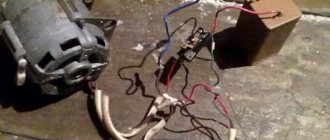
Re: Connecting a motor without a starter
With frequent switching on and off of a loaded machine, premature wear of the power contacts is possible. Carbon deposits form on it, which increases the contact resistance and, as a result, heats up. Starters, by the way, can also sin with this. Older people should remember Soviet times, when electricians on duty at production often had to change contacts on starters due to burnt contacts - fortunately they were replaceable and replaceable within the limits of their size.
Acshel Posts: 46 Joined: 02 Feb 2021, 18:32
Re: Connecting a motor without a starter
By itself! - PML, PME, PMA if I'm not confusing anything. Although in fact it wasn’t that long ago, and they’re probably still changing it here and there...)
Vadim84 Posts: 61 Registered: Jan 19, 2021, 5:59 pm
Connecting an electric motor according to a star and delta circuit
The main methods of connecting three-phase electric motors to the network are used: “star connection” and “delta connection”.
When connecting a three-phase electric motor with a star, the ends of its stator windings are connected together, the connection occurs at one point, and three-phase voltage is supplied to the beginning of the windings (Figure 1).
When connecting a three-phase electric motor using a “triangle” connection diagram, the stator windings of the electric motor are connected in series in such a way that the end of one winding is connected to the beginning of the next and so on (Figure 2).
Terminal blocks of electric motors and winding connection diagrams:
Without going into the technical and detailed theoretical foundations of electrical engineering, it must be said that electric motors with windings connected by a star operate smoother and softer than electric motors with windings connected in a triangle, it should be noted that when the windings are connected by a star, the electric motor cannot develop full power. When the windings are connected according to a delta circuit, the electric motor operates at full rated power (which is 1.5 times more power than when connected by a star), but at the same time it has very high starting currents.
In this regard, it is advisable (especially for electric motors with higher power) to connect according to the star-delta circuit; Initially, the launch is carried out according to the star circuit, after which (when the electric motor has “gained speed”), automatic switching occurs according to the triangle circuit.
Control circuit:
Connecting the supply voltage through the NC (normally closed) contact of the time relay K1 and the NC contact K2, in the starter coil circuit K3.
After turning on the starter K3, with its normally closed contacts it opens the circuits of the coil of the starter K2 with contacts K3 (blocking accidental switching) and closes contact K3 in the power circuit of the coil of the magnetic starter K1, which is combined with the contacts of the time relay.
When the starter K1 is turned on, the contacts K1 close in the coil circuit of the magnetic starter K1 and at the same time the time relay turns on, the contact of the time relay K1 opens in the coil circuit of the starter K3, and the time relay contact K1 closes in the coil circuit of the starter K2.
Switching off the winding of the starter K3, contact K3 closes in the coil circuit of the magnetic starter K2. After turning on the starter K2, it opens its contacts K2 in the circuit of the power coil of the starter K3.
Control circuit
Three-phase voltage is supplied to the beginning of the windings U1, V1 and W1 through the power contacts of the magnetic starter K1. When the magnetic starter K3 is triggered using its contacts K3, a short circuit occurs, connecting the ends of the windings U2, V2 and W2 to each other; the motor windings are connected by a star.
After some time, the time relay, combined with the starter K1, is activated, turning off the magnetic starter K3 and simultaneously turning on K2, the power contacts of K2 are closed and voltage is supplied to the ends of the motor windings U2, V2 and W2. Thus, the electric motor is switched on in a triangle pattern.
Circuit breaker
The main controller for electricity consumed in a modern apartment is a circuit breaker or simply a “machine”. On the electrical diagram it is located at the very beginning of the circuit, but physically it is usually located next to the electric meter.
Depending on the current strength for which the machine is designed, the maximum permissible power of all connected electrical appliances is set. For example, if the rated current load of the machine is 20 A, then the power of all connected electrical appliances should not exceed 20A x 220V = 4.4 kW. If you simultaneously turn on devices with a total power of 5 kW, then after some time the machine will turn off the power supply. On the one hand, it can be annoying when, simultaneously with a click, the light suddenly goes out and all electrical appliances stop working. But on the other hand, this is a guarantee of fire safety. By turning off the power supply, the machine simply did its job and protected us from major trouble.
To ensure that annoying outages do not occur and safety is maintained, you need to ensure in your apartment such energy consumption conditions under which the rated current of the machine, the power of electrical appliances and the cross-section of the conductors in the electrical wiring correspond to each other. By the way, the required cross-section of wires also depends on the material of the electrical wiring cores. Copper strands can be thinner than aluminum strands because copper has lower electrical resistance and is a better conductor of current.
If the circuit breaker turns off the voltage supply when the permissible power consumption is exceeded, this is a fairly common, one might say, normal situation. But besides this, emergency situations also happen. For example, a short circuit or current leakage controlled by an RCD. In this case, the machine turns off the voltage supply instantly. If this does not happen, the wiring will begin to melt and there will be a fire hazard.
Contact system on the contactor
Regardless of the standard size and manufacturer of electrical equipment, any three-phase contactor has a standard diagram of contacts and their connections. For ease of installation, all contacts are marked indicating their purpose. The marking is applied to the body of the device and looks like this:
- A1 (zero) and A2 (phase) – contacts for controlling the switching on and off of the contactor;
- Odd numbers 1, 3, 5 and markings L1, L2, L3 indicate the three-phase power input locations;
- Even numbers 2, 4, 6 and markings T1, T2, T3 indicate the connection points of the wires going to the current consumer;
- 13NO and 14NO are a pair of block contacts to provide the self-latching function.
Contact A2 is duplicated in the upper and lower parts of the device body for ease of switching. For the same purpose, the upper and lower (odd and even) group of power contacts can also be used to input or output power. When installing the contactor, you must be careful, otherwise the circuit will not work.
Incorrect phase connections must not be allowed. If you mix them up when installing the contactor, you will get reverse rotation of the motor. For this purpose, there are two ways of marking the insulation of cable cores - with numbers and color. The colors 1, 2 and 3 are yellow, green and red. The neutral conductor is white or marked with the number “0”. Connecting power contacts is not difficult. The main thing is the correct connection of the control voltage through the push-button station.
Connecting a magnetic starter via a push-button post
This circuit includes additional start and stop buttons. Both “Stop” buttons are connected in the control circuit in series, and the “Start” buttons are connected in parallel. This connection allows switching with buttons from any position.
Here's another option. The circuit consists of a two-button post “Start” and “Stop” with two pairs of contacts, normally closed and open. Magnetic starter with a control coil for 220 V. The power supply for the buttons is taken from the terminal of the power contacts of the starter, number 1. The voltage approaches the “Stop” button, number 2. It passes through a normally closed contact, along the jumper to the “Start” button, number 3.
We press the “Start” button, the normally open contact number 4 closes. The voltage reaches the target, number 5, the coil is triggered, the core is retracted under the influence of the electromagnet and sets in motion the power and auxiliary contacts highlighted in dotted lines.
The auxiliary block contact 6 bypasses the contact of the “start” button 4, so that when the “Start” button is released, the starter does not turn off. The starter is turned off by pressing the “Stop” button, number 7, the voltage is removed from the control coil and the starter is turned off under the influence of the return springs.
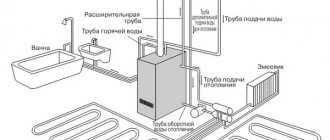
Connecting a heated floor to a thermostat
Such devices are used to regulate the temperature not only of electric heated floors, but also of water floors. There are several types of thermostats, from mechanical to electronic without programming and with software.
The temperature setting is set using a rotary controller or touch control. Floor thermostats with programmable control are more complex and more expensive. But these thermostats have more options for adjusting a comfortable temperature.
You can program the activation of heated floors at different times of the day, week, month and for different durations of operation. Such programmable devices help save energy. Thermostats for heated floors are designed for any electric heated floors, these are;
- a resistive cable that has high resistance. The resistive cable heats up when current flows through it;
— film heated floor has the form of a thin film with glued strips of carbon semiconductor;
— thermal roll mat. This is a heat-insulating film with a heating cable attached to it.
Overview of options
In manual mode, activation is carried out from a push-button station. The start button opens the contact to close, and the stop button works to open. The connection diagram for a self-retaining magnetic starter is as follows:
Let's consider the operation of the on and off circuits of a magnetic contactor. A push-button station of two buttons, when you press START, the phase comes from the network through the STOP contacts, the circuit is assembled, the starter retracts and closes the contacts, including the additional NO, which is parallel to the START button. Now, if you release it, the magnetic starter continues to operate until the voltage disappears or the thermal relay P for motor protection is triggered. When STOP is pressed, the circuit is broken, the contactor returns to its original position and the contacts open. Depending on the purpose, the power supply to the coil can be 220V (phase and zero) or 380V (two phases), the operating principle of the control circuits does not change. Switching on a three-phase electric motor with a thermal relay through a push-button station looks like this:
In the end it looks something like this, in the picture:
If you want to connect a three-phase motor through a magnetic starter with a 220-volt coil, you need to make the switch according to the following wiring diagram:
Using three buttons on the control panel, you can organize the reverse rotation of the electric motor.
If you look closely, you can see that it consists of two elements of the previous diagram. When you press START, the KM1 contactor turns on, closing the NO KM1 contacts, becoming self-retaining, and opening the NC KM1, excluding the possibility of turning on the KM2 contactor. When you press the STOP button, the chain is disassembled. Another interesting element of the three-phase reversible connection circuit is the power section.
On the KM2 contactor, phases L1 are replaced by L3, and L3 by L1, thus changing the direction of rotation of the electric motor. In principle, this circuitry for controlling three-phase and single-phase loads completely covers household needs and is easy to understand. You can also connect additional automation elements, protection, limiters. They all need to be considered separately for each specific device.
Using the above diagram for connecting a magnetic starter, you can organize the opening of a garage door by introducing additional limit switches into the circuit, using NC contacts in series with NC KM1 and NC KM2, limiting the movement of the mechanism.
Count the wires
The number of cores can be judged by the number of keys, but sometimes there are exceptions. Therefore, it is better to make sure that the required number of wires are laid in the wall. This will determine which switch you can install.
Take a close look at the mechanism. Count how many wires are connected to it and find out if there are any unused wires in the wall. There can be from two to four in total.
- Two wires - suitable for a single-key switch. You can control one or all lamps of an individual luminaire.
- Three wires - suitable for a two-key switch. You can control two groups of lamps in one chandelier or two separate lamps.
- Three wires - also three wires are needed for pass-through switches. You can control one or all of the lamps in a single luminaire from two different locations.
- Four wires - suitable for a three-key switch. You can control three groups of lamps in one chandelier or three separate lamps.
Read with this
- Connection diagrams for a magnetic starter for 220 V and 380 V + features of independent connection
- What could be the reason for the malfunction of the socket in one room, and why does it not work, but there is light?
- Instructions for connecting a three-key switch with your own hands
- How to install a socket
- How to replace an outlet in an apartment yourself
- Why is the LED lamp blinking?
- DIY touch switch rgb-light slider
- How to update old tiles in the bathroom
- How to cut metal using a grinder
- The door handle creaks: causes of the problem and solutions
Connection diagram for a 220 V magnetic starter
Here, the current is supplied to the magnetic coil KM 1 through a thermal relay and terminals connected in a chain of buttons SB2 for turning on - “start” and SB1 for stopping - “stop”. When we press “start”, electric current flows to the coil. At the same time, the starter core attracts the armature, resulting in the closure of the moving power contacts, after which voltage is supplied to the load. When “start” is released, the circuit does not open, since the KM1 block contact with closed magnetic contacts is connected parallel to this button. Thanks to this, phase voltage L3 is supplied to the coil. When you press “stop,” the power is turned off, the moving contacts return to their original position, which leads to de-energization of the load. The same processes occur when the thermal relay P operates - a break in the zero N supplying the coil is ensured.
Tags: automatic, sconce, varistor, type, switch, generator, engine, house, , grounding, replacement, star, like, contactor, , magnet, magnetic, marking, installation, power, load, voltage, nominal, lighting, connection , principle, wire, project, start, , work, size, relay, switch, row, light, connection, resistance, means, circuit, ten, type, current, triangle, three-phase, , phase, photo, shield, electric motor, electrical panel , anchor