A time relay (timer) for light is a device that automatically turns on and off electric lighting at specified time intervals.
Have you ever felt your way along the dark paths of your dacha when you appeared there after sunset? Were you upset by the sight of a light bulb burning around the clock in the empty entrance of a multi-story building? Are the fish and algae in your aquarium suffering from lack of light due to your forgetfulness?
A time relay for lighting control will help you avoid such troubles.
These smart devices create comfortable conditions for human life and save energy.
All of them are plastic monoblocks with controls located on the front panel and differ in a number of parameters.
Types of light timers
Based on the operating principle:
- electronic;
- electromechanical.
By frequency of work:
- daily allowance;
- weekly;
- astronomical;
- countdown;
- random on/off;
- universal.
By installation method:
- rosette;
- stationary, installed on a DIN rail in an electrical panel or in an installation box.
According to operating conditions:
- according to the permissible power of consumers;
- according to the degree of protection from external factors.
Let's look at each type in detail.
List of used literature
- Figurnov E. P. “Relay protection” 2004
- Iglovsky I. G., Vladimirov G. V. “Handbook on low-current electrical relays” 1984
- Filipcheiko I, P., Rybin G. Ya. “Electromagnetic relays” 1968
- Gurevich V.I. "Electrical relays. Device, principle of operation and application. Engineer's Handbook" 2011
- Andreev V.A. “Relay protection of power supply systems in examples and tasks” 2008
- Bass E.I., Doroguntsev V.G. “Relay protection of electric power systems” 2002
Characteristics of light timers
Electronic time relay for light
This is a microprocessor controlled device. Programmed using buttons located on the front panel.
The readings are displayed on a liquid crystal display. The power supply is a battery or accumulator.
Its advantages:
- ability to set short switching intervals (up to 1 minute);
- high precision (deviation < 1 sec/day);
- saving the program during a power outage;
- visibility of specified indicators;
- a wide selection of models that meet any requirements for frequency of operation, installation method (in an electrical panel and in a socket) and operating conditions.
The only drawbacks that can be noted are more complex programming and potential problems when the battery life is exhausted.
Any lighting control tasks are solved using electronic relays.
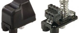
Electromechanical time relay
This is a device in which the timekeeping mechanism operates via a synchronous electric motor powered from the network.
It is used on a daily basis and, less frequently, on a weekly basis.
It is programmed using levers located on the front panel and a graduated wheel.
There are mobile socket and stationary models mounted on a DIN rail or in a mounting box.
The advantage of electromechanical devices is ease of setup, but in a number of parameters they are inferior to electronic ones:
- lower accuracy;
- higher minimum switching interval (10-15 minutes);
- After turning off the power supply, models that are not equipped with a battery or battery will crash the program.
A typical malfunction for this type of relay is failure due to wear of the adjustment wheel gears.
The breakdown cannot be repaired on your own - you will have to contact service.
Algorithms for operation of time relays, functional diagrams, symbols
What algorithms can time relays operate by?
It was already mentioned above that any relay can operate to close, open and switch contacts with the necessary control action. And the time relay provides for either a pause after such an impact, or even compliance with a certain cyclic operation.
There are many algorithms for operating time relays. The diagrams below will discuss the most commonly used ones.
In the diagrams, the top graph (blue) shows the supply voltage supplied to the relay. The bottom graph is the output voltage going from the relay to the actuator (to the load). Red arrows show the ranges of the set response delay.
One more note. Control signals for relays can be supplied in different ways.
- This may be the general power supply voltage supplied to the device. Such relays are called power-controlled.
— A separate external signal supply circuit is used for control.
The diagrams below, just for clarity, will mainly show (with one exception) the algorithms for power controlled relays. But for the second option they are basically the same.
Algorithm 1
Algorithm diagram No. 1
Time relay with switch-on delay. After turning on the power, the output signal will be transmitted to the load after the set pause T .
Algorithm 2
Algorithm diagram No. 2
The output signal in this embodiment is transmitted to the load immediately after turning on the power. But after a set interval T is interrupted.
Algorithm 3
Algorithm diagram No. 3
The load is turned on simultaneously with the supply of general power. But the shutdown is performed after a pause T from the moment the relay supply voltage is removed.
Algorithm 4
Algorithm diagram No. 4
Cyclic operation of the time relay, with a pause at the start. After supplying the supply voltage, the output signal to the load appears after interval T1. This signal is maintained for a certain set interval T2. Then an opening occurs, with a second pause T1, after which the load is turned on again for a time T2 - and so on until the supply voltage is completely removed.
Algorithm 5
Algorithm diagram No. 5
One of the options with permanently connected power and control using an external signal. When a control pulse is applied (or, conversely, when it is removed - shown in highlighted color and dotted line), the relay is activated and switches power to the load. Power is supplied for a set period T1, after which it is automatically turned off until the next control pulse arrives.
These algorithms can be called basic. And from them, as from “bricks”, much more complex circuits can be built, implemented in relays of various designs and models.
One of the most important characteristics of a time relay is the functional diagram
By the way, the graphic diagrams shown above are called relay functional diagrams, and are usually indicated on the device body or in its technical documentation. That is, when choosing the required product for certain needs, knowing how to read such diagrams, you can find a suitable model.
Below, two illustrations will demonstrate the variety of functional diagrams of time relays offered for sale. This is shown as an example only, as in reality the choice may be much wider. Please also note that some relays may have several outputs to the load, as well as several channels for receiving an external control signal.
Examples of functional diagrams of power-controlled time relays.
Functional diagrams of time relays - table A
Examples of functional diagrams of time relays with external signal control.
Functional diagrams of time relays - table B
Values of time intervals T, T1, T2, etc. most often the user can install it. True, there are time relay models in which the response time is already preset and cannot be changed. But these are devices for special purposes, usually installed in protection circuits for electrical devices and installations. Naturally, the delay value in this case is indicated in the technical description of the product.
One time relay can implement several algorithms for its operation, with a choice. And functional diagrams and contact diagrams are usually depicted on the product body.
Designations of time relay contacts on diagrams
When choosing a time relay, you must be able to understand not only the functional diagram, but also the contact layout. Usually the following accepted notations are found:
A. Contacts that operate to open the circuit.
Symbols of contactor time relays operating to open
1 — arc facing down: response delay after control voltage is applied;
2 — arc facing down: response delay after removing control voltage;
3 - two oppositely directed arcs: delays both when the control voltage is applied and when it is removed.
B. Contacts that work to close the circuit.
Symbols of contactor time relays operating on closure
The trigger conditions, of course, don’t need to be described - they are the same as in the previous example.
Installation
When choosing a device, think about what purposes it will serve and how to install it.
Socket relays
The use of socket relays is possible with lighting fixtures that have a standard plug for connecting to a household AC network.
The undeniable advantages of this type of equipment:
- compactness;
- mobility;
- ease of installation and operation;
- installation without connecting wires.
However, they are unsuitable for controlling the apartment lighting system as a whole and are not designed for significant power; in this case, you can pay attention to programmable sockets with Wi-Fi.
Stationary timers
If the consumer is faced with the task of managing not individual devices, but the lighting network of a home or business, then it is necessary to choose stationary devices.
They are mounted in a mounting box or on a DIN rail of a distribution board. Requires additional, in comparison with rosette ones, effort and material costs.
But it provides unity of system control and the ability to connect large capacities.
Electromagnetic
It is used only in electrical circuits with direct current and includes components such as a magnetic conductor element, a control type winding, and a short-circuited turn.
The delay in switching is created due to the short-circuited winding. It contains one turn, which is fixed on the core component of the magnetic circuit. This turn has the appearance of a sleeve. It is made from metal - aluminum or copper.
To provide a delay interval for operation, an auxiliary magnetic flux is provided. Adjustment is possible by changing the gap parameters or the tension of the return spring. Adjustable within 5 s.
The relay is common in circuits that control the acceleration or braking of an electric drive. The time delay is affected by temperature. If the winding temperature deviates by 10°C, then the delay changes by 4%.
Exploitation
When choosing a device, take into account the operating conditions: think about what equipment you will connect to it and in what place you will install it.
Permissible power of consumers
Strictly follow the rule: the total power of consumers connected to the timer should not exceed its own power.
The necessary data is in the technical documentation of the equipment and on the package labels.
Protection of time relays from external factors
Adverse effects of external factors (water, dust) can adversely affect the operation of the timer. Therefore, the degree of its protection (IP - Ingress Protection Rating) must correspond to the operating conditions.
Connecting a 380 V asynchronous motor via a starter with a 220 V coil
This circuit differs only in that three phases are connected to contacts L1, L2, L3 and three phases also go to the load. One of the phases is energized to the starter coil - contacts A1 or A2. In the figure this is phase B, but most often it is phase C as it is less loaded. The second contact is connected to the neutral wire. A jumper is also installed to maintain power supply to the coil after the START button is released.
Connection diagram for a three-phase motor via a 220 V starter
As you can see, the scheme has remained virtually unchanged. Only it added a thermal relay that will protect the engine from overheating. The assembly procedure is in the next video. Only the assembly of the contact group differs - all three phases are connected.
Manufacturers and models of light timers
The desire to improve living comfort and save energy resources is increasing the popularity of light timers. As a result, electrical companies have mastered the production of this type of product.
Let's look at what models European manufacturers offer consumers.
Hager Group (Germany)
The company was founded in 1954 in Blieskastel. Produces low-voltage equipment, electrical cabinets, switches, automatic machines, GSM sockets. The main factories are located in Germany and France. Annual net profit is more than 1 billion euros.
Manufactures electronic and electromechanical light relays.
| Hager EG071 | Hager EH011 | Hager EG203 |
| Operating principle | ||
| electronic | electromechanical | electronic |
| Periodicity | ||
| weekly | daily | weekly |
| Switching time | ||
| 1 minute | 15 minutes | 1 minute |
| Number of contacts | ||
| 1 | 1 | 2 |
| Accuracy | ||
| +/- 1 sec/day | not indicated | +/- 1 sec/day |
| Rated current | ||
| 16 A | 16 A | 16 A |
| Installation method | ||
| On Din rail (1st place) | On Din rail (1st place) | On Din rail (1st place) |
| Voltage | ||
| 230 V | 230 V | 230 V |
Models of the highest quality are presented. The most expensive EG203 has a number of additional advantages: a random on-off function, a five-year power reserve from a lithium battery, and a key that blocks unauthorized program changes.
FINDER (Italy)
Founded in 1954, the company specializes in the production of motion sensors, remote-controlled sockets, and timers. The product catalog includes more than ten thousand items.
Search on the site
To organize this, a coil is introduced that bypasses the start button, which is placed on self-feeding, organizing a self-retaining circuit.
At the same time, the spring holds the upper section of the magnetic circuit in a raised state. When you need to connect 2 conductors to a clamp, you need their ends to be straight and on both sides of the clamping screw. Phase A through KM1. The control circuit is protected from a short circuit by the fuse PU. Under normal circumstances, the relay contact P is closed. See the following video for assembly procedure. Engine power depends largely on the iron and wire cross-section.
The latter is connected to the output of one of the MPs, and the first is connected to the output of the second. The design may also include, as additional elements, a protective relay, electrical fuses, an additional set of terminals, and a starting device. To start, you need to press the START button, after which the coil circuit of the magnetic starter will close and attract and close the PM contacts to start the engine and the PM4 contact, which will make it possible to continue working when you release the start button and not turn off the magnetic starter, called self-retaining. Normal state when contacts are open.
This diagram is usually drawn on the lid. KM2 contacts.
Three-phase voltage is supplied to terminals F1, F2, F3. It is removed from contacts T1, T2, T3. They do not allow both starters to turn on at the same time. The housing, made of electrical insulating material, completely protects a person from accidental electric shock. Therefore, the starter control buttons, which are called a push-button post, have two pairs of contacts - normally open, open, normally closed, NO, NO and normally closed, closed, break, NC, NC. This universalization of all buttons of the push-button post is made in order to anticipate possible support schemes instant engine reverse.
As a rule, they are manufactured in a single dielectric housing, and one of them is red. When current passes through the coil, the core becomes magnetized and attracts the plate with the switching device.
Relay heaters are designed to accommodate the maximum amount of current flowing through them. Indicated by green, white or other neutral color. Reversing magnetic starters in a single-phase network. Reversible electric motor connection diagram.
How to choose
When choosing a device, first of all, identify the goals you want to achieve. In accordance with them, you can determine the required set of options and the accuracy of the work.
There is no need to chase multifunctionality and raise the bar when there is no need for it: there is no need to use an astronomical timer to maintain a home aquarium with a daily cycle and on-off periods of at least half an hour.
Do not forget to check the relay power: it cannot be less than that of the consumers planned to be connected. And, of course, the IP (degree of protection) must correspond to the operating conditions.
Contactors and starters - what's the difference?
Contactors and starters close and open contacts in electrical circuits. The devices are a solenoid, they can operate in DC and AC circuits of different power - from 10 V to 440 V DC to 600 V AC. Have:
- a certain number of working (power) contacts through which voltage is supplied to the connected load;
- a number of auxiliary contacts - for organizing signal circuits.
So what's the difference? What is the difference between contactors and starters? First of all, they differ in the degree of protection. Contactors have powerful arc extinguishing chambers. This leads to two other differences: due to the presence of arc arresters, contactors are large in size and weight, and are also used in circuits with high currents. For low currents - up to 10 A - only starters are produced. By the way, they are not produced for high currents.
The appearance isn't always that different
There is one more design feature: the starters are produced in a plastic case, with only the contact pads exposed outside. Contactors, in most cases, do not have a housing, therefore they must be installed in protective housings or boxes that will protect against accidental contact with live parts, as well as from rain and dust.
In addition, there is some difference in purpose. The starters are designed to start asynchronous three-phase motors. Therefore, they have three pairs of power contacts - for connecting three phases, and one auxiliary one, through which power continues to flow to operate the engine after the “start” button is released. But since a similar operating algorithm is suitable for many devices, a wide variety of devices are connected through them - lighting circuits, various devices and devices.
Apparently because the “filling” and functions of both devices are almost the same, in many price lists the starters are called “small contactors”.
Photo
Adjusting instruments with a digital scale
Setting up devices of this type is illustrated using the example of a timer with a digital scale of the “REV Ritter” brand, plugged into a regular power outlet. The period of validity of its temporary delay is, as a rule, limited to one day, which is quite enough for domestic conditions. Instructions for setting up such a relay include the following points:
- Plug the device into a power outlet.
- Move up all the adjusting elements (segments) aligned around the circumference of the adjustment disk.
- Move down only those that correspond to the set time.
- The center disk indicator is set to the current time.
If the segments located between the numbers 18 and 20 are shifted down, the desired load will turn on after the 18-hour interval and turn off after two hours. The design of such a semi-automatic device provides the ability to organize up to 48 work cycles (on and off) within two calendar days.
Types of such devices
On the shelves of electrical stores you can find various time relays, including:
- analog automation;
- digital devices;
- time relays that plug into a socket and are an adapter.
Analog devices are becoming increasingly rare today. This is not surprising, because the functionality of digital ones is much greater. With their help, you can, for example, plan lighting cycles for a week in advance.
Socket relays are used in everyday life. For example, periodic power supply to the fan is required. Here you don’t even have to figure out how to connect a 220V time relay. You just need to plug it into a power outlet. And the fan itself will be connected to a time relay via a plug.
Configuring electronic-mechanical analog relays
Industrial automation systems, as well as various household modules, are often equipped with electromechanical devices, the design of which allows for adjustment using potentiometers.
Electromechanical type of time counting device with parameter adjustment by potentiometers. There are various configurations of such devices, which makes it possible to use them in circuits of varying complexity.
On the front panel of the housing of such devices there is a potentiometer rod (or several rods) designed for rotation with a screwdriver blade. A marked scale of installation values is applied around the circumference of the rod(s).
The slot on the rod for the screwdriver blade is a kind of pointer that changes its position when the rod rotates. By placing this pointer opposite certain values of the marked scale, the desired parameter can be adjusted.
Multichannel device of electronic-mechanical type. Adjustment is easy and simple by rotating the potentiometers with a screwdriver. The front panel also has LED status indication
Devices of this type (for example, NTE8 ) are widely used in control circuits for ventilation systems, heating modules, and artificial lighting devices.
What are they used for?
The use of time relays is common in domestic conditions. For example, when operating an air conditioner, actions may be required that are carried out cyclically at certain intervals. For example, cooling or heating (depending on weather conditions), which are performed with an hour break.
The switch will help you warm up your food before dinner. If the owner leaves the house for some time during the cold season, it is better for him to turn off the heating. But if he only does this for a couple of days, he can arrange for it to be turned on periodically with minimal parameters.
Socket type timer Source sovet-ingenera.com