Well sources for obtaining clean water belong to the category of individual water supply. To do this, you need to connect surface or submersible electric pumps. They turn off when the main line is full, because the equipment cannot work without interruptions. To do this, connect automation, which is responsible for controlling the shutdown and on cycles.
Automation for the pump maintains normal operation of the system.
What is automation for a pump and why is it needed?
In areas where it is not possible to connect to the general water supply system, a well is often drilled, which becomes a source of water.
But to create a complete plumbing system you need a pump. With its help, water will be pumped into the pipes, and in order not to start it manually, automation for the well is used. This is a device for automatically starting a pump or monitoring the presence of water. If there is automation, the pump can independently pump liquid into the system or supply it to the upper floors. Also, if you have automation and a heating boiler, you can make a heating system that will pump water to create pressure and drive it through pipes not only into radiators, but also into a shower or sink. Using automation, you can prevent overheating of the motor and avoid idle operation of the dispenser (when there is no water in it).
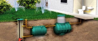
Example of a control unit with a tank Source inhouse-spb.ru
Types of automation
Automation for well pumps has existed for quite a long time and now you can purchase devices of three different generations. They differ in the complexity of the mechanism, the functions they can perform, and also in cost.
First generation
The first generation includes the simplest devices that perform specific functions. With their help, it is impossible to create an autonomous water supply system, since most often these devices are mechanical.
Example of simple first generation automation Source www.italflexo.cz
The pressure switch is one of the most necessary and useful mechanisms in the water supply system. Inside such a device there is a capsule with a spring that closes the contact if the pressure drops. After the water supply stops, the motor pumps up the liquid and opens the terminals. This device must be used in combination with a storage tank. There must be a pressure sensor (pressure gauge) on the body of the relay or near its connection.
Example of a spring pressure control relay Source 4-stihii.ru
A hydraulic accumulator is a storage tank into which water is collected. It helps to avoid frequent activation of the pump and mitigate water hammer, for example, when closing a tap. There is a membrane installed in the tank that squeezes out the water. For it to work, the pressure in the system must be increased so that it is higher than in the membrane.
When the tap is open, water is squeezed out of the tank and the membrane is filled with air. If the pressure drops to the value set on the relay, the power circuit will close and the container will be refilled with liquid. The hydraulic accumulator is most often made of ferrous metal or stainless steel, and a pressure gauge is installed on their body, which shows the pressure inside the tank and helps adjust the water supply.
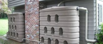
Storage tanks with different sizes Source maxidom.by
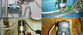
Automation for a pump with a hydraulic accumulator and a pressure switch needs to be supplemented with a float and a relay that prevents idle operation. The first device is needed to control the presence of water. If it falls below the minimum mark, the float will turn off the power to the pump so that it does not overheat. It can be mounted separately on the pump wall or built into the system. Floats are most often installed inside the automation for a submersible pump.
To adjust the water level, you can install an electrolytic sensor instead of a float. It is suitable for placement inside wells and consists of 2 conductors that close the power circuit only if they are in water.
Press control is also used for similar purposes. It consists of a magnetic curtain that is lowered into the water and a reed switch (sealed contact). If there is water in the system, the curtain rises and closes the circuit using a magnetic field, and if there is no liquid, it lowers and interrupts the current supply.
Fluid flow switch (press control) Source ebayimg.com
The level of protection activation depends on the size of the petal, and for finer adjustments there are models in which you can change the distance between the reed switch and the shutter. Flow switches are rarely used for outdoor pumps. Due to the nature of the mechanism, it does not need idle protection.
The idle speed lock is needed to prevent the pump from burning out. It is installed complete with other elements, for example, a tank and a water pressure regulator. The principle of operation of the blocker is similar to the pressure regulator, only it opens the circuit if there is not enough water in the system. The power off limit can be set using the adjustment screws. Most often, such blockers are installed on pumps that stand on the surface.
Power cut-off unit during idle operation Source geyser.com.ua
Second generation
This type of automation unit for a well pump usually consists of electrical devices with sensors that supply data to a microcircuit, which ensures autonomous water supply. Electronic devices are mounted on a pumping station without a hydraulic accumulator, since the sensors operate constantly, but to compensate for water hammer it is recommended to install a tank of at least 5 liters.
Temperature sensors must be installed inside such a unit to ensure that the motor or other components do not overheat, as well as an emergency engine shutdown unit when jammed. In the second generation, all elements are most often located in one case and have a graphical interface for displaying data.
Idle speed blockers and press control are installed inside such blocks. The advantage of such systems is that they take up little space if you do not install a storage tank. Elements in the design can be mechanical (to save money) or electronically controlled (more expensive).
Third generation
The devices retained the advantages of the second generation and acquired a new ability to regulate the speed of the electric pump engine. This is done by fine tuning the electronics. This increases the service life of the pump. With a small water intake, the engine operates at low speeds. If consumption increases, pump power increases. Economical operation allows you to significantly save on electricity bills.
Third generation devices.
Third generation automatic modules are most suitable for water supply pumps without a hydraulic accumulator. The system always has the same pressure, water is supplied in an even flow.
Modular automation for wells: advantages and disadvantages
The latest generation automation is assembled in a small unit and is easy to connect. Advantages over early electromechanical devices are in expanded capabilities, these are:
- fine electronic tuning;
- simple control and management;
- equipment service life increases;
- electricity is saved;
- Water supply with constant pressure is more convenient to use.
Modular automation is not without its drawbacks. Consumers attribute this, first of all, to high cost. It is 10 times higher than the price of simple devices. Work depends on the quality of the power supply; power surges are poorly tolerated. Many modules are configured for electric pumps of the same brand.
Video description
Features of setting up the relay are described in the following video:
When changing standard relay settings, it is important to understand that there is always a difference of 1.4 atm between the indicators. To change this, you need to tighten another nut located on the control panel of the device
In this way, the difference between the device’s response limits can be increased to 2.03 bar. To reduce it, do the opposite - unscrew the adjusting nut.
Design of a protective relaySource 2proraba.com
When setting up dry-running protection, it is important to consider other recommendations:
- Do not set the lower limit of pump shutdown too low. The presence of an error of 0.3 bar in the device will lead to the fact that the relay will not be able to stop supplying voltage in time.
- It is not better to set the values too high for the protection to trigger. In such a situation, the system may lose power for no apparent reason.
- The minimum pressure set to trigger the protection leads to difficulties in starting the pumping station. To turn on the equipment, you will have to drain the water from the accumulator.
- With a significant volume of water consumption, a “rollback” of pressure occurs when it sharply decreases to critical levels. To avoid unnecessary shutdown of the system, it is recommended to lower the lower value for relay activation.
Installation of automation
To install automation on a pump, you need to know how to connect the components correctly. The diagram may differ for different blocks, and its features are most often found in the accompanying documentation for the block. As an example, we can consider the installation of the first generation system, since it is the simplest.
First, you should put an “American” (special fitting) on the thread of the hydraulic accumulator, so that you can then connect a tee to it. It is also useful for conveniently replacing components, since the fitting is easily removed. A sensor for adjusting and measuring pressure must be installed in the thread of the tee.
All connections should be sealed with fum tape to prevent leakage and pressure loss. Next, one end of the pipe needs to be secured to the hydraulic accumulator, and the other to the pump.
Pump control circuit diagram
When the Eurocube is empty, all sensors are not in contact with water. The inputs of logic element D1.3 receive a high-level voltage through resistor R4 from the power source. In this case, the output D1.3 will be logical zero. It goes to pin 5 of element D1.2, which, together with element D1.1, forms a regular RS trigger with inverse inputs.
Since pin 6 of D1.2 is zero, the trigger is set to a state where output D1.1 is also zero, and a logical one appears at the output of element D1.4. The current from output D1.4 through resistor R6 enters the base of transistor VT1, it opens and relay K1, the winding of which is connected in its collector circuit, connects the pump with its contacts, through connector X2 and X2, to the power supply.
Fig.1. Schematic diagram of an automatic water pump control device.
The pump begins to pump water into the Eurocube. Sensors E2 and E3 are immersed first. A logical zero is set at the inputs of element D1.3, and a unit at its output. But the RS trigger on D1.1 and D1.2 does not change its state. As soon as the water level reaches sensor E1, pin 1 of D1.1 is set to logical zero.
The RS trigger switches and now output D1.4 is zero. Transistor VT1 closes and relay K1 turns off the pump. Eurocube is full.
Subsequently, water from the “Eurocube” is consumed for various needs, and its level in it decreases below the E1 sensor. The voltage at pin 1 of D1.1 rises to a logical one, but this does not affect the state of the RS trigger in any way. The pump will be turned on only when the E3 sensor “dries out”.
Details and setup
Relay K1 type BS-115C-12A-12VDC with a 12V winding and contacts for 240V and 12A. The relay can be replaced with any analogue, complete or functional. If this is not a complete analogue, you will need to make changes to the installation.
The KT604AM transistor can be replaced with any KT602, KT603, KT604 or KT815.
Diodes 1N4004 - any diodes with a voltage of at least 400V.
Transformer T1 is Chinese, unknown brand, from a broken mains power supply with an output voltage of 12V. You can choose any similar one. You can buy a cheap 12V power supply and use it instead of the T1-VD2-VD5-C2 circuit.
Capacitors must have a voltage of at least 12V.
The K561LA7 microcircuit can be replaced with a K176LA7 or a foreign analogue.
The installation diagram is shown in Figures 2 and 3. Installation can be done on a printed circuit board, but the author did not have such an opportunity, so a piece of construction plastic was used as the basis for the board. In general, it is very similar to getinax, but one side is colored, with a pattern, and the other is brown.
Holes were drilled in the workpiece according to Fig. 2, then all components were installed in them according to Fig. 3. The terminals are slightly bent so that they do not fall out. Then, copper wire was taken from the telephone cable, stripped, tinned, and laid with one or two turns wound onto the terminals of the parts, in accordance with the connection diagram in Figure 2. Afterwards, all connection points are soldered.
Of course, this is not as durable and reliable as a printed circuit board, but it also works if there are no serious mechanical impacts on the installation during operation.
If the installation is done on a printed circuit board, you need to take Figure 2 as a diagram of the location of the printed tracks and mounting holes. Naturally, the tracks will be significantly wider than shown in the diagram. And take Figure 3 as a diagram of the arrangement of parts.
In principle, no adjustment is required. If all parts are in working order and there are no installation errors, it should work right away. The only thing that may be required is the selection of R2 and R4 - if there are few impurities in the water, its conductivity is low, and their resistance, in this case, will have to be increased.
This machine can be used where there is a central water supply, but works intermittently, to fill the reserve tank by replacing the pump with a solenoid valve.
Installing protection against dry running of the pump yourself. Step-by-step instruction
You can see the connection diagram for the pressure switch and dry run protection in the figure:
The installation procedure is as follows:
- The relay is connected to the water supply line in the right place, the connections are carefully sealed, and checked for leaks.
- Remove the protective casing of the device.
- We connect the pump to the terminals as shown in the figure:
- Connect the grounding.
- We adjust the sensitivity of the relay by tightening or loosening the nuts of the spring-loaded contacts:
After this, all that remains is to test the system, make sure that the relay does not interfere with the normal operation of the pump and properly turns it off after it goes dry.
Design and principle of operation
The design of measuring devices of this type is determined by the following parameters:
- Functionality, depending on this device, is usually divided into alarms and level meters. The former monitor a specific tank filling point (minimum or maximum), while the latter continuously monitor the level.
- The operating principle can be based on: hydrostatics, electrical conductivity, magnetism, optics, acoustics, etc. Actually, this is the main parameter that determines the scope of application.
- Measuring method (contact or non-contact).
In addition, the design features are determined by the nature of the technological environment. It is one thing to measure the height of drinking water in a tank, another to check the filling of industrial wastewater tanks. In the latter case, appropriate protection is necessary.
How to choose?
The choice of a water level sensor in a tank depends on many factors, the main ones:
- Composition of the liquid. Depending on the content of foreign impurities in the water, the density and electrical conductivity of the solution may change, which is likely to affect the readings.
- The volume of the tank and the material from which it is made.
- The functional purpose of the container is to accumulate liquid.
- The need to control the minimum and maximum level, or monitoring of the current state is required.
- Admissibility of integration into an automated control system.
- Switching capabilities of the device.
This is not a complete list for selecting measuring instruments of this type. Naturally, for domestic use it is possible to significantly reduce the selection criteria, limiting them to the volume of the tank, the type of operation and the control circuit. A significant reduction in requirements makes it possible to independently manufacture such a device.
Briefly about the main thing
A relay that prevents the pump from running dry is an extremely important device. It does not allow idling, which is dangerous due to the failure of the main components of the water supply system.
When choosing a relay, the characteristics of the pump and the level of pressure it creates are taken into account
The installation location of the protection is taken into account, which affects the requirements for its operating parameters. The connection diagram for the relay and related units is selected taking into account the manufacturers’ recommendations
The device is also connected to the electrical network and the protection response limits are set. The relay is adjusted using screws (by turning them in one direction or the other).
The connection diagram for the relay and related units is selected taking into account the manufacturers’ recommendations. The device is also connected to the electrical network and the protection response limits are set. The relay is adjusted using screws (by turning them in one direction or the other).
Tips for selection and application
Before choosing a pressure regulator, you should understand how high the water supply is required, since the standard pressure is from 1.5 to 3 atm, and to supply water for every 5 m you need to add another 0.5 atm to this figure. Therefore, for the 2nd floor the minimum pressure will be from 2 to 3.5 atm.
You should also install a block on the pump that prevents damage from voltage surges. It also acts as a stabilizer for the current power supplied to the system. At critical values, the protection will turn off the power, and if the indicators are slightly different, but are not limiting, then it equalizes the voltage.
Before you start using the automation and pump, it is recommended to carefully configure all parameters, since they may be different for each well. Also, the settings depend on the presence of a hydraulic accumulator and its volume.
Installation of a surface electric pump
To install a surface electric pump and external stations, it is necessary to make and equip a well. In private and country houses, on summer cottages, it is recommended to make a caisson. It can be metal, plastic, concrete. Such designs differ in shape - round, square or rectangular.
Plastic caissons are considered economical options. They are light in weight and easy to set up and install. But groundwater can lift the material outward, causing the structure to collapse. For a country house, you can buy concrete caissons, which are made of individual rings. This material allows water to pass through, so there will be moisture inside the structure.
The best option is to use metal, but it is expensive and requires costs for arrangement and installation. Inside the caisson there is water intake equipment, a hydraulic accumulator, and a pump. In surface pumps, the intake depth is no more than 9 m. To connect surface equipment, a deep and large hole is needed.
Installation diagram of a surface electric pump.
The suction pipe can increase the level of water pressure in the system and protect the components. It is lowered 1 m. After installation, connections are made, the functionality of the equipment is checked and errors are eliminated.
Control circuit (shutdown) of the pump for pumping water by level
I’ll start with a scheme for pumping water, that is, when you are faced with the task of pumping water to a certain level, and then turning off the pump so that it does not idle. Take a look at the diagram below.
It is this kind of electrical circuit that can ensure pumping of water to a given level. Let's look at the principle of its operation, what's here and why.
So, let’s imagine that water replenishes our tank, it doesn’t matter whether it’s your room, a cellar or a tank... As a result, when the water reaches the upper reed switch SV1, voltage is applied to the coil of the control relay P1. Its contacts close, and a parallel connection to the reed switch occurs through them. Thus the relay is self-retaining. The power relay P2 is also turned on, which switches the contacts of the pump, that is, the pump is turned on for pumping. Next, the water level begins to decrease and reaches the reed switch SV2, in this case it closes and supplies a positive potential to the coil winding. As a result, there is a positive potential on both sides of the coil, no current flows, the magnetic field of the relay weakens - relay P1 turns off. When P1 is turned off, the power supply to relay P2 is also turned off, that is, the pump also stops pumping out water. Depending on the power of the pump, you can select a relay for the current you need. I didn't say anything about the 200 ohm resistor. It is necessary so that when the SV2 reed switch is turned on, a short circuit to minus does not occur through the relay contacts. It is best to choose a resistor such that it allows relay P1 to operate reliably, but at the same time has the highest possible potential. In my case it was 200 ohms. Another feature of the circuit is the use of reed switches. Their advantage when used is obvious, they do not come into contact with water, which means that the electrical circuit will not be affected by possible changes in currents and potentials in various life situations, be it salty or dirty water... The circuit will always work stably and without misfires. No circuit configuration is required, everything works immediately, with the correct connection.
After 2 months...
Now what was done a couple of months later, based on the requirements to reduce power consumption in standby mode. That is, this is already the second version of everything that I talked about above. You understand that according to the diagram above, a 12-volt power supply will be constantly turned on, which, by the way, also consumes not free electricity! And based on this, it was decided to make a circuit to activate the pump for pumping out or filling water with a current in standby mode equal to 0 mA. In fact, this turned out to be easy to implement. Take a look at the diagram below.
What causes dry running?
Most often, submersible pumping equipment stops showing signs of life due to idle operation.
It will not be possible to return a damaged unit under warranty, since this situation is the fault of the owner, that is, incorrect operation was allowed. Common reasons leading to dry running of equipment:
- The wrong height for installing the pump in the well or well has been selected. Most often this happens when the owner of the source has not calculated its depth in advance. The pump is started, pumping water, but when the liquid reaches the equipment installation level, there is nothing left to pump, which is why it begins to “pull” air. Under such operating conditions, the motor of the device begins to get very hot and eventually overheats.
- Due to natural reasons, the water level in the well decreased. This often happens when, after pumping out the liquid, it does not have time to accumulate again. The source must be given time to replenish its reserves of the working medium, and only then begin pumping.
- A surface-type pump is installed, the suction pipe of which has lost its tightness. Because of this, in addition to water, it begins to suck in air masses, which disrupts the performance of the cooling system.
If the pumping equipment is not protected by a sensor or dry-running relay, the pump becomes very hot, which leads to burnout of the electric motor and other parts. If the design of the pumping unit contains elements made of plastic, then due to insufficient cooling and lubrication they are first deformed, which reduces the performance of the pump. It will not work for a long time in this mode: overheating will cause the shaft to jam and the motor to break.
Control circuit (shutdown) of the pump for filling water by level
If you take a quick glance at our entire article, you will notice that I simply did not provide the second diagram in the article, except for the one above.
In fact, this is a self-evident fact, because what essentially distinguishes the pumping circuit from the pumping circuit, except that the reed switches are located oppositely. That is, if you rearrange the reed switches, or reconnect the contacts to them, then one circuit will turn into another.
Let me summarize that in order to convert the above diagram into a water pumping scheme, swap the reed switches. As a result, the pump will be turned on from the lower sensor - reed switch SV1, and turned off at the upper level from reed switch SV2.
Parts List
- You can use any of these transistors: KT815A or B. TIP29A. TIP61A. BD139. BD167. BD815.
- GK1 – lower level reed switch.
- GK2 – upper level reed switch.
- GK3 – emergency level reed switch.
- D1 – any red LED.
- R1 – resistor 3Kom 0.25 watts.
- R2 – resistor 300 Ohm 0.125 watt.
- K1 – any 12 volt relay with two pairs of normally open contacts.
- K2 – any 12 volt relay with one pair of normally open contacts.
- I used float reed contacts as signal sources for replenishing water in the container. The diagram is designated as GK1, GK2 and GK3. Made in China, but of very decent quality. I can't say a single bad word. In the container where they stand, I treat the water with ozone and over the years of work there has not been the slightest damage to them. Ozone is an extremely aggressive chemical element and it dissolves many plastics completely without any residue.
Now let's look at the operation of the circuit in automatic mode. When power is supplied to the circuit, the lower level float GK1 is activated and power is supplied to the base of the transistor through its contact and resistors R1 and R2. The transistor opens and thereby supplies power to the relay coil K1. The relay turns on and with its contact K1.1 blocks GK1 (lower level), and with contact K1.2 it supplies power to the coil of relay K2, which is an actuator and turns on the actuator with its contact K2.1. The actuator can be a water pump or an electric valve that supplies water to the container. The water is replenished and when it exceeds the lower level, GK1 turns off, thereby preparing the next cycle of work. Having reached the upper level, the water will raise the float and turn on GK2 (upper level), thereby closing the chain through R1, K1.1, GK2. The power to the base of the transistor will be interrupted, and it will close, turning off relay K1, which with its contacts will open K1.1 and turn off relay K2. The relay, in turn, turns off the actuator. The circuit is prepared for a new cycle of work. GK3 is an emergency level float and serves as insurance if the upper level float suddenly does not work. Diode D1 is an indicator that the device is operating in water filling mode. Now let's start making this very useful device.
We place the parts on the board.
We place all the parts on a breadboard so as not to make a printed one. When placing parts, you need to take into account to solder as few jumpers as possible. It is necessary to make maximum use of the conductors of the elements themselves for installation.
Final look.
The water level control circuit is sealed.
The circuit is ready for testing.
We connect it to the battery and simulate the operation of the floats.
Everything is working fine. Watch a video about tests of this system.
Installing a protective relay in a system with a hydraulic accumulator - is it worth the risk?
The protective relay will function normally with any pipeline that does not have a hydraulic accumulator in its design. On the other hand, you can install the relay in conjunction with a hydraulic accumulator, however, such installation will not provide complete protection against dry running.
The reason for this lies in the operating principle and structural features of the sensor: the protective relay should be mounted in front of the hydraulic accumulator and the fluid pressure switch. In this case, a dry running valve is installed between the protective device and the pumping unit.
In this case, the relay membrane will be under the influence of constant pressure created by the accumulator. This is a fairly typical scheme, but in most cases it will not help protect the pump. For example, consider the following case: when the pump is turned on and pumps out liquid from an almost empty container, the remaining liquid remains in the hydraulic accumulator. Since the lower pressure threshold is set by the manufacturer at 0.1 atmospheres, there is actually pressure, but the pump will run idle.
As a result of this, the pump motor will stop working only in cases where the hydraulic accumulator becomes completely empty, or when the motor itself burns out. As a conclusion, we can say that it is better to equip systems with hydraulic accumulators with other protective devices.