A relay is a switch. And not quite ordinary. When a light bulb in a hallway lights up due to the sound of footsteps, it’s not magic, it’s a relay working. In this article we will talk about the purpose of the relay and the principle of its operation.
There are many types and classifications of relays. But we will talk not only about them, but also about what a relay is and how it works. Go!
Why do you need a voltage control relay?
Household electrical appliances are designed for a voltage of 220-240 V. From time to time, emergency situations arise in the electrical network. The voltage in the outlet jumps up or down. Jumps can disrupt the operation of household appliances or completely destroy them.
Voltage drops in the network
A common case of voltage drops is a zero break. In this case, in one phase the voltage drops below the permissible level. On the other, on the contrary, there is a significant increase in voltage up to 380V.
Another situation is typical for old houses with poor electrical wiring and loose contacts. Due to the poor condition of the cables and their overload, the voltage in the sockets can drop to 170 V or lower. This is dangerous for electric motors of washing machines and refrigerators.
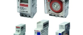
A voltage control relay protects electrical appliances. This small device is located in the distribution panel of the apartment. It has a compact design, is conveniently mounted on a DIN rail and performs its task completely autonomously.
Additional Information. It is necessary to distinguish voltage control relays from all kinds of stabilizers and UZMs. All of the listed devices are used to protect household appliances. The stabilizer is an active device. He is able to independently adjust the voltage in the apartment. The RN performs a simpler and more passive function. It simply turns off the consumer when the permissible threshold is exceeded and, in itself, does not affect the voltage in any way.
On the causes of instability in power grids
Not only the uncontrolled distribution of extreme consumers throughout the power grid can lead to equipment failure. Over time, electrical wiring becomes obsolete. And especially in houses with electric stoves and electric heating, over time it leads to the most significant losses. The star power supply circuit with a neutral wire, which is used everywhere, ends with the distribution of phases both between apartments and between consumers in production.
Therefore, a voltage drop from switching on consumers in some places is inevitably accompanied by an increase in voltage at low-power consumers in other phases. This is the most dangerous situation, to overcome which these consumers are promptly disconnected from the power grid. Otherwise, many of them will be damaged. The most dependent in such situations are incandescent light bulbs. But even when the voltage drops, there are “leaders”. Usually these are washing machines. Air conditioners and refrigerators are not far behind them.
Purpose of buttons and pins
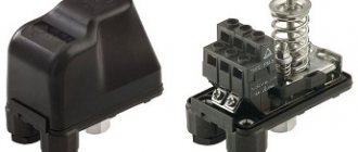
There are 3 contacts on the front panel of a standard voltage limit relay. They are designed for connecting neutral and phase conductors. Looking from left to right, the contacts have the following purposes:
- Common neutral wire. This contact is bifurcated into 2 points.
- Supply voltage input. The phase coming from the meter is connected to it.
- Exit to the apartment. This wire will turn off when there is a voltage surge or sag.
Pins 2 and 3 are normally open power contacts. If the voltage between 1 and 2 is within normal limits, then 2 and 3 are closed, and the phase can freely pass into the apartment network.
Voltage relay device
The voltage control relay has a simple operating principle. The internal controller continuously measures the network voltage. If it goes beyond the norm, then the electromagnetic relay turns off the apartment. The device is digital. It responds both to excessively high voltage and to low voltage.
Switch-on time delay
LV is characterized by a switch-on delay. If the voltage falls below the permissible norm, the device will turn off and break contacts 2 and 3. When the voltage returns to normal, the relay does not turn on. It waits for a while. For example, 15 seconds. This is necessary to avoid false activations of the LV. A control for setting this parameter is provided on the front panel of the device.
The relay body has buttons with a display. They allow you to configure the operating voltage range and response delay time. Detailed information about setting up the device is contained in the instruction manual.
Principle of operation
The operation of a monitoring device of this type is based on measuring voltage values in the external supply network. When the values fall below the specified values or exceed the upper set limit, the relay opens its power contacts, thereby disconnecting the consumer’s network from the external power supply.
Connection diagram to a single-phase power supply network for an apartment or house
After a certain time period, the device automatically closes the power contacts and supplies power to the internal power supply network. To prevent cyclic restarts of the power section, the design of the device includes a turn-on time delay (delay interval), which can be set by the manufacturer or set manually. If the voltage level after disconnection does not reach the specified values, the device will not close the power contacts.
Technical specifications
The main characteristics of the LV include operating voltage, number of connected phases and maximum throughput power. Below are the parameters of one of the popular relays - RV-32.
| Characteristic | Meaning |
| Supply voltage | 220 V |
| Maximum active power of the consumer | 7 kW |
| Load current limit | 32 A |
| Measurement error | +/-1 % |
| Degree of protection against dust and moisture | IP20 |
| Number of relay operating cycles | 100 thousand |
| Working temperature | from -5 to +40°C |
| Limit cross-section of connected wires | 6 sq. mm |
From the characteristics it follows that the relay is powered by a mains voltage of 220 V. The internal contacts are capable of continuously passing a current of 32 A, which corresponds to a consumer with a power of 7 kW. IP class 20 says the device is not suitable for use in wet areas or outdoors. It can be installed in a special electrical panel. 100 thousand operating cycles is the number of switching on and off of the relay that it can withstand without destruction.
Voltage relay DigiTOP Vp-50A IP20
Manufacturer analysis
Voltage relays are manufactured by many manufacturers with factories located throughout the world. The table below shows the most popular models in our country, indicating the manufacturers and type of device mounting.
| Model | Manufacturer country | Response thresholds V | Rated current A | Degree of protection | Workmanship |
| ZUBR D16 | Ukraine | 120-210 ; 220-280 | 16 | IP 20 | Higher |
| Adecs ADC-0110-40 | Ukraine | 100-400 | 0-40 | IP 20 | Higher |
| Sven OVP-11F | Finland | 185-255 | 10 | IP 20 | Higher |
| Novatek RN-111 | Ukraine | 160-220; 230-280 | 16 | IP 40 | Higher |
| TESSLA D32 | Ukraine | 120-210; 220-280 | 32 | IP 20 | Higher |
Types of launch vehicles
Various types of devices need protection from voltage surges. Some of them operate on household voltage 220 V and consume minimal power. Examples of such devices include smartphone chargers or LED light bulbs. Others also operate on 220 V, but already consume thousands of watts of power, for example, electric kettles and irons. Still other devices require three-phase power supply of 380 V. A conventional single-pole LV is not suitable for them. Among such consumers are industrial machines and powerful asynchronous motors. Therefore, all relays for voltage control are usually divided by type of housing and type of load.
By case type
This classification indicates which devices and in what quantities can be connected to the relay. According to the type of execution, the launch vehicle is divided into 3 types:
- rosette;
- in the form of an extension;
- with installation on DIN rail.
The first type is the easiest to use. This surge protection relay plugs directly into an outlet. On one side of the case there is a corresponding connector in the form of a plug. On the other part of the device there is a standard socket for connecting the load. This type of LV can be quickly removed and connected to another location.
The second type is made in the form of an extension cord. On its surface there are several sockets for loading. Unlike type 1, this relay is equipped with a cable and plug. The device is convenient for stationary connection of office equipment.
The third type is the most professional. The pH is installed in the shield. It has an extended list of functions, high throughput, and at the same time protects all electrical appliances in the apartment.
By number of phases
Electrical consumers operating on alternating current are divided into 2 groups. The voltage control relay has a similar division. Namely:
- single-phase LV;
- three-phase.
Single-phase modification is suitable for home use. These relays are installed in apartments, garages and cottages. They pass through one phase and zero. That's why they are called single-phase.
The operating voltage for such LVs is 220V. Their contacts are designed for a current of 30-40 A, which corresponds to the maximum values for residential wiring. The device has a minimal list of settings and, if you read the instructions, is suitable for use by an ordinary person without specialized education.
Three-phase voltage monitoring relay ZUBR 3F
The second type of relay is more complicated. It controls voltage on 3 phases simultaneously. This modification is suitable for units consuming 380 V from a network. The relay has an expanded list of adjustments and requires minimal experience in setting up automation systems.
Installation
The limiter is mounted directly in the electrical panel. Its installation is not particularly difficult and can be done by any electrician who has experience in performing other similar work.
Various devices are produced for operation in networks with one and three phases and with different voltages and controlled loads. Therefore, it is necessary to purchase a device that matches the project. To connect the limiter, you must read the attached instructions.
First of all, you need to connect power to the device. The equipment has one or three holes through which the load wires are threaded. They control power. Inductive current sensors are located in these holes. Single-phase devices have one hole, three-phase devices have three holes.
There are pins on the device panel from which control signals are supplied to the contactors. The connection diagram is simple enough to do it yourself. During installation, it is necessary to use high-quality wires with the required cross-section and ensure that all contacts are securely fastened.
Some devices may be specially equipped with additional signal contacts, which are necessary for connecting various automation and alarm circuits. Limiters can be connected to personal computers using RS-232 or RS-485 interfaces to set parameters through a personal computer, rather than through the device menu.
When operating the device, it is necessary to monitor the frequency of protection operation. Frequent shutdowns may indicate a short circuit, faulty electrical appliances or network. If frequent alarms occur, it is necessary to carry out a technical check of the equipment and electrical insulation of the network.
Common connection schemes
There are also differences in the power of consumers that are connected through the LV. One is enough to supply phase and zero. Others require three-phase power. For each load power category, a corresponding relay connection diagram is required. Therefore, it is customary to distinguish 3 ways to activate these protective devices:
- single-phase LV;
- three-phase;
- connection diagram via contactor.
Connecting a single-phase LV
The circuit is used to connect 220 V consumers. It is suitable for both an apartment and a separate device.
Initially there is a single-phase LV, supply and outlet lines. Installation of the circuit is carried out according to the plan below:
- The common neutral wire is connected. The corresponding terminal is on the relay. It is designated by the letter "N". Depending on the model of the device, there may be two zero terminals. In this case, the zero from the supply line is connected to one contact, and the outgoing line to the other.
- Then the phase wire of the outgoing line is connected. On the device body this terminal is marked “L2”, “output L” or “out L”.
- The third stage is connecting the phase wire of the supply line. Voltage is always present on it, regardless of whether the LV operates or not. In a standard electrical panel, this conductor comes from the output of the meter or automatic switch.
Diagram for three-phase voltage monitoring relay
Different models of three-phase voltage control relays have a different set of terminals for connecting wires. There are 8 of them as standard. Mains voltage terminals (4 pcs.) are needed to supply three controlled phases and zero to the device. On the device body they are designated L1, L2, L3 and N. Output relay terminals (4 pcs.) are used to connect subsequent protection and automation devices. They are marked “NO” for normally open contacts, and “NC” for normally closed contacts.
The connection diagram is assembled in 2 stages:
- The phase and neutral wires of the supply line are connected to the RN terminals. Here you need to pay attention to the maximum permissible current of the contacts. As a rule, if the consumer is three-phase, then it consumes high power. The relay must be rated for these values.
- Subsequent devices are connected to the relay output. For example, a contactor, various alarm devices or “failure” indicator lamps.
Note! Expensive three-phase LVs are capable of monitoring not only voltage, but also a number of other network parameters. For example, critical phase imbalance and the correctness of their alternation. These functions are important for the correct operation of asynchronous motors and thyristor converters.
Connecting loads over 100 kW using a contactor
Some electricity consumers draw hundreds of amperes from the network. No launch vehicle is capable of handling such powers. In this situation, a separate contactor is used. It must be connected to the output relay.
In this scheme, the RN simply monitors the state of the network and generates a low-current control signal for the contactor. Its retractor coil is connected in series with the output of the voltage control relay. The main load current flows directly through the contactor.
Important! The LV should not be placed near powerful sources of radio interference, such as transformers or cordless phones. The interference they emit can affect the relay's measuring circuit and lead to false alarms.
How to read labels
When choosing a voltage relay, you need to learn how to correctly read the markings and understand them. Such knowledge is necessary so that upon purchase you do not receive a device with other technical characteristics.
All necessary markings are present on the device on its front side. The device indicates, first of all, the response thresholds, which are indicated in volts. There can be two of these values, provided that the voltage relay has the function of adjusting the lower and upper thresholds. Next, the device indicates the rated current. This value indicates the maximum current that can pass through the device. A prerequisite is to indicate the degree of protection and its power on the device body.
The 63A voltage relay DIGITOP MP-63 is a multifunctional and powerful device
Also, the terminal numbering must be indicated on the device.
Recommendations for selection
From the above it follows that there are many types of voltage control relays. The selection is carried out taking into account the specific situation in which the RN will have to work. The most significant criteria for choosing a voltage monitoring relay are:
- Single-phase or three-phase network. An option is practiced when instead of one three-phase relay, 3 single-phase ones are installed.
- Relay type. Plug-in, designed for 1-3 consumers. They can withstand current up to 16 A. Modifications for DIN rail are more powerful. Through them it is possible to connect the entire apartment. The current passed is 40-80 A.
- Permissible relay current. For an ordinary apartment, a device capable of passing 30-40 A is suitable. This current is greater than the cross-section of household wiring will allow, but it is better to take the LV with a power reserve of 1.5-2 times. This way the device will last much longer.
- If a relay is purchased to connect a single household appliance, then before purchasing you should find out what its current consumption is. In this situation, it is enough to make a reserve of 30-50%.
Additional Information. There are voltage monitoring relays equipped with a built-in ammeter. These devices allow you to monitor the current consumed by the apartment. They can be used to provide protection against short circuits or network overloads.
Setting LV response thresholds
The overvoltage protection relay is configured after analyzing the current state of the electrical network and wiring . It is necessary to pay attention to factors such as:
- Voltage at the socket. It is 220 V only on the pages of textbooks. The actual voltage in the network can be in the range of 190-240 V. It makes no sense to configure the LV to turn off when it drops to 210 V, if the voltage in the outlet rarely rises above 200 V. This is especially true for rural areas and in a private house.
- Power of household appliances. Some types of equipment consume high currents at the moment of startup, which sharply reduces the voltage in the network. This dip must be taken into account in order to select the lower protection threshold.
- At night the opposite happens. People are sleeping. Most of the electrical appliances in the house are turned off. The voltage in the network can go off scale up to 230-240 V. This phenomenon is taken into account when choosing the upper response rating.
Installation and configuration of voltage relays
Checking pH using a multimeter
Full tests can be carried out using special equipment in an electrical laboratory. However, the accuracy of the output voltage readings can be checked with a conventional multimeter. The device must be switched to the mode for measuring alternating voltage up to 700 V. This is indicated on the switch as “ACV 700”.
Then use a multimeter to determine the voltage at the output of the LV and compare this value with the readings on the display of the protective device. You need to understand that both devices have some measurement error. The readings should be approximately the same. A difference of 2-3 V is not a reason to panic. But if the differences are more significant, then there is a malfunction in the launch vehicle.
The use of LV will protect household electrical appliances from voltage surges. To do this, you will need to select the correct settings for its operation. Approximate values can be found in the device data sheet.
The voltage control relay is selected taking into account the number of supply phases and the maximum power of the consumer. It is advisable to purchase a protective device with a current reserve of 20-30%. If you need to control the current consumption, it is better to install a device with a built-in ammeter.