Ensuring comfort and safety is one of the main goals of architects, structural engineers and designers when working on any new project. These are mandatory conditions for proper rest, leisure, and professional activities of a person. At any modern residential, commercial, administrative or industrial facility, one of the most important engineering systems is the power supply network. Lighting, household appliances, office equipment, industrial and commercial equipment - everything runs on electricity. Master button installation in such conditions, this is an effective way to make using the electrical network easier and safer.
Very often, on the way to work or during the day, thoughts occur to a person about whether he forgot to turn off the coffee maker, iron, turn off the lights, or the TV. And it’s not just a waste of electricity, but also a safety issue. A common cause of fires is household electrical appliances that are not turned off. Installing a master switch completely solves this problem.
Master button is a system that allows you to turn off power to an object or individual power branches with one click of a button or even remotely
Control circuits
Electromagnetic contactors do not have mechanical locking in the on position. To ensure that the rod is held during operation, a self-retaining circuit is used. This is a fairly convenient technique that allows you to switch the coil power circuit with various protection and automation devices of the electric drive. The exception is assemblies controlled by PLC or relay automation.
The simplest self-retaining circuit includes one additional blocking normally open contact. The coil power circuit is connected through a normally open contact of the start button. The second circuit is connected in parallel; it consists of a series-connected blocking contact and a normally closed contact of the “Stop” button. Thus, when the contactor is turned on, a blocking contact is closed, which is held during operation and supplies power to the coil. If it is necessary to stop, the coil power circuit is opened with the “Stop” button.
Contactor self-retaining circuit: L1, L2, L3 - three-phase power supply phases; N - neutral; KM - magnetic starter coil; NO13-NO14 - additional normally open contact; M - asynchronous motorThere are also more complex control schemes
Thus, the use of a normally closed contact of the start button of one contactor can be used to prevent the simultaneous operation of two starters, which, in particular, may be important when constructing reversing circuits or may be due to other technological needs. The same principle can operate when using a normally closed blocking contact of one contactor, which is connected in series with the start button contact of another.
Scheme of reverse engine starting: KM1, KM2 - coils of magnetic starters; NO KM1, NO KM2 - normally open contacts of starters; NC KM1, NC KM2 - normally closed contacts of starters; KK - thermal relay
The self-retaining circuit can also include limit switches, dry contact sensors and various protective devices. Automatic activation of the contactor is also possible; for these purposes, the button is replaced or duplicated by parallel activation of limit switches or sensors. Thus, the complexity and control schemes of an automated electric drive are practically unlimited.
Exceptions to the rules
Exceptions to the rules listed above are quite possible, although quite few.
Firstly
, sometimes the switch has to be literally placed upside down simply because there is not enough wire. Those. This solution is the only way to avoid the labor-intensive drawing of a new wire.
Secondly
, sometimes the traditional switch position is changed for reasons of convenience. For example, horizontal orientation is used near a chair in situations where it is convenient to turn it on with a linear movement of the hand in the direction “away from you.”
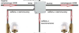
Connection diagram for PV cables in the distribution box
Changeover switch installation diagrams
An important step is assembling the pass-through switch circuit in the distribution box. 4 wires with 3 cores go to it - a power cable from the automatic light control from the switchboard, a cable to the 1st and 2nd switch, a cable to the light source.
During the work you need to focus on the color of the wire:
- phase – white/gray;
- zero – blue/brown;
- earth – yellow-green/black.
The assembly provides the following step-by-step algorithm:
- Connection of the neutral core coming from the input cable of the machine and the neutral wire going to the lamp with terminals.
- Connecting all earth conductors in the presence of a grounding conductor. The ground from the input is thrown onto the outlet ground using terminals.
- Ground connection to the housing of the lighting device.
- Coupling the phase from the input cable with the phase from the outgoing cable and fastening them to a common terminal in the 1st switch.
- Connection of the common wire of the 2nd switch with the phase of the lighting cable terminal.
- Connection of secondary outgoing conductors of switches No. 1 and No. 2.
- Applying voltage and testing the design.
Two or three wire cable?
Next, run the second cable from the top of the junction box to the switch installation location. For a single-keyboard player it should be a two-wire VVGng-Ls 2*1.5mm2.
At the same time, many experienced electricians still recommend initially placing a three-wire wire in the groove. Although a simple light switch does not require a third core (it will remain unused), however, in the future, you can easily replace a single-key switch with a two-key or pass-through one.
There is no need to re-drill the walls or tear off the wallpaper.
It is no longer possible to connect more “complex” switches with a two-wire wire. The schemes there will be completely different.
The same applies to the bathroom. If during the repair process you install a three-core wire on a single-key switch, then later it can also be changed, and the exhaust fan can be powered from the second key.
The cable is stripped on both sides, and its cores are labeled L and L1.
- L – incoming phase
- L1 – the same phase, but already going to the lamp
Design and principle of operation of a two-key switch
The design of the two-key switch is quite simple. It consists of:
- Two keys (moving parts up and down).
- Housing (shell), which is removed before starting work with electricity.
- Terminal blocks (those places to which voltage or current is supplied).
Switch design
In rare cases, the third element - terminal blocks - can be replaced in the design with screw terminals. The difference is that the former hold the wire for a long time and securely, and the latter do the same, but without pinching the wire, twisting it, so the first option is easier to connect and lasts longer. The design may also include additional lighting - a dimmer located on each key.
Inside the two-key switch without backlight there are two wires running parallel to each other + an input for the phase. Each of the terminals suitable for the keys can independently open or close a contact that turns on one lamp, a second lamp, or all lamps at once.
Two-gang switch wires
The principle of operation of the switch is to vary the degree of illumination:
- You can turn on only one key so that one light bulb (or the first group of lights) lights up.
- It is possible to turn on the second key - the lighting will change, since some parts of the room will be clearly visible, while others will be slightly darkened.
- The third option is to turn on all the lamps at once - both keys are in the “on” position - then the room receives maximum illumination.
Some two-gang switches consist of two single-gang devices isolated from each other. In this case, it is customary to call them modular.
In addition to the external component, such a device can also perform the functions of saving energy and creating a varied atmosphere. Two-button switches also increase safety, since when they are installed in a room, the number of points with electrical voltage is reduced.
Before starting work on preparing to connect the switch, we suggest that you familiarize yourself with the diagram of the two-key switch below:
The switch disconnects zero, not phase
The second common mistake is connecting through the switch not the phase conductor, but the neutral one.
A single-key switch, as well as other types of light switches, should always break the phase. This is done for your own safety, so that when replacing a light bulb in a socket or repairing a chandelier, you will not get an electric shock.
Please note that even if you initially did everything correctly, before reaching into the contacts of the lamp after turning off the light, always check the absence of voltage with an indicator screwdriver.
The fact is that after time, the phase and zero can change places. Even without your participation. How is this possible, you ask?
Elementary. An illiterate electrician from the management company, when replacing your single-phase meter, could have mixed up the wires and connected the neutral wire to terminal “1”, and the phase wire to terminal “3”. Or accidentally swap the wires from terminals “2” and “4”.
As a result, in all distribution boxes in the apartment, phase and zero will automatically change places. And the light switch, which was originally connected correctly, will begin to break the neutral wire.
Therefore, the rule “turn it off - check that there is no voltage” is the key to your safety.
What is a master switch
Modular contactor
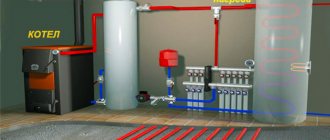
The contactor is a modular element mounted on a DIN rail and provides convenient load switching in a home electrical system. Its performance characteristics also depend on the selected contactor. For example, if a master switch with four groups of contacts is installed, the maximum permissible switching power of each of them will be around 24 amperes. In the vast majority of cases, such a switch is enough to turn off the electricity in your apartment or country house without any problems.
If the room uses single-phase power with a power of up to 20 amperes, it will be quite enough to install a two-pole contactor.
The simplest option for controlling a contactor is to use a main disconnecting device, which will be located indoors. This device looks like an ordinary switch that operates in two positions - “on” and “off”. When turned off, the light immediately disappears in the entire room, regardless of the position of the other switches, while when the system is turned back on, the light will appear only where it was turned on.
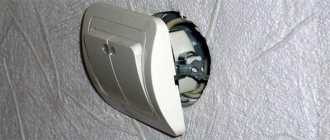
The switch is turned off with the up or down key
When installing the switch in the mounting box, pay attention to the position of the key when turning the light on and off.
According to the recommendations, the switch should be positioned so that when you press the key down, the light turns off, and when you press the button up, on the contrary, it turns on.
It is believed that in an emergency it is much easier to reach out with your hand and press the key down, thereby interrupting the electricity. The same applies to switches and modular circuit breakers in the panel room.
For rotary bags, electricians have their own unspoken rule, which is based on the position of its handle.
“It works - it works. It’s lying there – it’s not working!”
To be fair, it must be said that there are no clearly stated prohibitions on installing a light switch in a certain way and in no other way. Please remember that this is just a recommendation.
And everything is determined primarily by the brand and manufacturer of the product.
Using thermal relays with magnetic starters
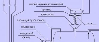
The possibility of triggering the thermal relay (1) is provided in case of an emergency. The circuit contact (4) is broken, followed by disconnection of the coil and return of the core to its original state by special return springs. After disconnecting the contacts in this way, the dangerous voltage is removed in the emergency area.
Connecting a magnetic starter together with a thermal relay provides reliable protection of electrical units from possible overloads. These devices serve as an effective addition to automatic machines, the bimetallic strips of which cannot always protect during an accident. Although, the principle of operation of a thermal relay is the same as that of the thermal element of an automatic protective switch. However, the thermal relay does not automatically switch off, but only sends a set signal to perform this operation. It must be accurately and competently recognized, and put into practice in a timely manner.
A thermal relay equipped with power contacts can be directly connected to a magnetic starter without the use of conductors. However, products from different manufacturers may not match, fit or interact with each other.
Each thermal relay is equipped with two groups of contacts, independent of each other - normally closed and normally open. To break the circuit, a closed contact is used, operating through the STOP button. All working contacts are present in the circuit intended for control. They are connected directly next to the coil, but can be placed in other convenient places.
The actuation process of the thermal relay is completely invisible from the outside. Returning to the original state is carried out using a small button located on the panel. You do not need to transfer the contacts immediately, but only after the relay has cooled down, otherwise they will not be securely fixed. Before the very first use, it is recommended to press the button to avoid careless switching during transportation.
Contactless key reader
This option is much more convenient and reliable.
Probably everyone has a drop key on their keys for a gate or intercom:
On the wall we will need to place a key reader with a built-in controller, for example, Matrix IIK
From the outside it looks like a white rectangle with a small LED. You need to supply 12V power to it; there is a relay on the board. There are two operating modes: sending a short pulse when a programmed key is applied, or turning the relay on/off when a key is applied. You can program all your keys. Any EmMarine format keys (drop keys) are supported, as well as contactless cards of this format. There are models that support more copy-protected, but less common Mifire cards.
Works with both contactors and pulse relays. The most interesting thing is that this reader can be hidden by completely covering it with wallpaper, for example. The reading range is about 1-2 centimeters. The main thing is not to cover it with metal elements.
That is, firstly, it can be invisible, secondly, you do not need to carry a separate key or card, and thirdly, it cannot be activated accidentally.
This reader is intended for access control systems; it has a connector for connecting an “exit button”, upon pressing which the controller will also change the state of the relay or give an impulse. You can display this button somewhere and use it as a backup option in case you lose the key.
Basics
To turn on magnetic starters and contactors, push-button posts are used. These are devices that have 2 or 3 buttons such as “Start” and “STOP” or “Forward”, “Back” and “STOP”, there are other less common options. These buttons are a non-latching button with a normally closed and normally open pair of contacts.
Starters and contactors are electromagnetic switching devices. In order for its power contacts to close, voltage must be applied to the coil. It will attract the core (anchor) on which the contacts are attached (the design may vary). When you remove the voltage from the coil, the device will turn off and its power contacts will open.
In addition to power ones, these devices have block contacts (usually several groups of them). They are not able to withstand heavy loads, but are designed to implement a self-retaining circuit and indications. The fact is that if you simply apply voltage to the coil through the push-button post, the device will turn on, but when you release the button, it will immediately turn off. This is necessary, for example, in winches and other lifting mechanisms, but not in circuits that operate for a long time without stopping, such as lights and electric motors of ventilation systems.
To avoid this, a self-retaining circuit is needed - a normally open block contact is connected in parallel with the “START” buttons on the push-button station.
Typically, such switching devices are used to connect high-power electrical appliances to the network: heating elements, motors, or, in our case, large lighting installations.
The essence of electricity
Let's try to explain the work of electricity in the most accessible words. We also know from physics lessons that the very essence of electricity is such that the phase always tends to discharge to zero. It is between the electricity-carrying and grounding flow that various types of devices are included in the circuit. Then a discharge occurs in them, forcing them to work.
In particular, this is how the filament or diode circuit in a lighting lamp works. The filament or diode circuit has its own resistance, which is balanced so that the lamps, when the network is closed through them, do not burn out, but begin to glow. And in essence, it doesn’t matter which wire goes to the switch - zero or phase, if zero is supplied to the lamp itself from one contact and phase from the other, it will work anyway. This will not affect the performance of the device in any way. This is only for security reasons.
Connection diagram for a 380 V magnetic starter
Some characteristics of magnetic starters can be seen in the table. The differences between a magnetic contactor and a starter are very conditional. First of all, it makes it easy to work with an asynchronous motor. Was this article useful to you? While some machine, such as a sawing machine, was operating, the voltage in the network was lost. I give examples of articles in which heating elements are turned on through starters: Look at the diagram for reversing the motor below: 9. Diagram for connecting a three-phase motor through a starter at B As you can see, the diagram has remained virtually unchanged. The starter coils are also switched on from the controller outputs. If this product is a circuit breaker that has thermal protection, it will trip due to heat in the frame. Reversible circuit for connecting a three-phase motor through magnetic starters To increase safety, a thermal relay has been added, through which two phases pass, the third is supplied directly, since protection in two is more than enough. And if it consists of two separate starters, a special mechanical interlock is placed between them. The organization of signal circuits is more complex. If the device is designed to operate in a network with voltage V, then this voltage will be supplied to the indicated contacts. Contactor/Magnetic starter, home use + theory. ABB ESB. Master switch
Bottom line
As can be seen from the description, installing home switches is not difficult. In comparison, installation of a vacuum circuit breaker in production requires sophisticated equipment and qualified personnel. Special alloys and high-strength bolt ties are used.
And the contact groups of household electrical appliances are designed for direct connection of wires, without the use of special terminals.
What is a modular contactor and what is it for?
According to its functional purpose, the modular contactor KM belongs to the switching equipment for remote control of powerful loads operating at direct or alternating current. They break current circuits in several places at once, and this differs from electromagnetic relays, which break the circuit at only one point.
Quite often, modular contactors work in conjunction with auxiliary devices - set-top boxes, thermal relays, blocking devices and other modular devices. As a result of such combinations, equipment is obtained that has special properties and is capable of performing specified functions. So, when installing a delay module, you get a contactor with a delay function, and a thermal overload relay transfers the contactor to the category of a magnetic starter.
With the help of auxiliary elements, the capabilities of the main devices are significantly expanded, their performance characteristics are improved, and installation is simplified.
At their core, contactor devices are considered modified versions of a starter, which additionally contains a thermal relay and a contact group for starting the electric motor. Low voltage electromagnetic starters, reversible and non-reversible. The first option includes two identical contactors, with the same rated current. It has a mechanical or electrical interlock that prevents the main contacts from closing at the same time.
The protective functions in these devices are performed by electrothermal current relays and other similar devices. Low power electrical contactor, used as an intermediate relay. It is designed for low-current circuits and has a large number of switchings. Using this device, it is possible to connect many additional sections and control their on/off.
Contactor selection criteria
You should not choose a contactor yourself - this is a task for a highly qualified electrician who has experience working with this type of switching devices. And the difficulty here is not only in correctly calculating the parameters, but also in choosing a manufacturer.
Contactors are not cheap equipment, so often at the procurement stage the contractor or customer wants to save money. As a result, a model of a low or mid-price segment is purchased. When turned on, they make loud clicks, during operation they can buzz when the contacts stick, and their service life is lower. It is better to immediately buy a reliable contactor that will fully pay for itself during operation.
Criterias of choice:
- Rated current, voltage - the electrician calculates the parameters of the current in the switched circuit, taking into account the loads from each point of consumption, correction factors, starting surges;
- Number of poles – determines the number of phases and switched electrical circuits;
- Voltage of the electromagnetic coil - in most cases, in apartments, private houses, and offices, models with a voltage of 220V are used.
An experienced electrician takes into account some additional parameters, including the class of the contactor (the life of the switch depends on it), the degree of protection, etc.
Practical Application Examples
The digital device should be switched to dialing mode.
In this case, the same lamp can be controlled from each floor and, if desired, from the basement.
A pass-through switch allows you to close one of two circuits. How to make a pass-through switch from a regular one: work order. It is not always possible to quickly find a suitable model of a device that allows you to control lighting from two points at once. Connecting conductors using special WAGO clamps.
Let's look at the following circuit diagram: Three things have changed: From breakout box S1, switch S2 has two cables connected to it, which are used to power the other light switches. There are open type PV for connection with open wiring and closed type for connection with wiring running inside the walls. A diagram with two pass-through switches that allows control of two loads. The following video will help you understand in more detail the diagram for connecting a switch from two places: It clearly shows how to connect the wires in the junction box so that there are no difficulties during operation.
Electric lighting is an indispensable companion of any modern apartment. The first is used to connect a contact at the input, the second - at the output. To connect them, in the simplest case, you need two two-core cables. However, their functionality is very different.
Places of use In addition to the bedroom, similar situations can arise quite often. Before starting work, use a voltage tester to make sure that there is no electrical potential on the power cables, preferably on all terminals coming out of the box. The crossover device is connected between the feedthroughs. When choosing the appropriate option, you should buy a model with the same number of keys for each point. In such situations, it becomes necessary to control lighting from two places; it is for solving such problems that the so-called pass-through switches are designed.
Types of crossover and pass-through switches
With modern electrical installations, pass-through switches have become more often used, which can turn off or turn on, for example, the lighting in a room at the entrance to the room and at the same time near the bed or, for example, on both sides of the corridor. For the first case, socket boxes will be required for installation. It is also beneficial to use a similar scheme in small houses, the size of the floors. Electrical diagram for switching on a lamp from three places. An ordinary switch only closes and opens a circuit. Installing two ordinary switches in different places in the room will not allow you to control the lamp from two places at once.
Similar to switch S1, we connect the protective conductors with one connector and the neutral conductors with the help of a second connector. Conclusions and a useful video on the topic You can learn from the videos presented how the use of circuits for connecting pass-through switches from several places occurs in practice. Thanks to these jumpers, the phase to the lighting source can be supplied from either one or a second switch, which will allow you to turn on the lighting from several places. Such solutions are useful in large houses and small apartments. In order not to be mistaken about what kind of switch it is, you should familiarize yourself with the connection diagram, which is present on the switch body. Connection diagram for a two-key pass-through and crossover switch from two or more places.
What colors should the wires have in the electrical wiring of an apartment?
Any conductor purchased for electrical wiring must contain a core with a blue (blue) braid. It is this that is recommended to be used in the network as a neutral wire. If the apartment has a third wire - direct grounding, it is recommended to run a yellow-green wire on it. All other wires (it can be white, brown, black, etc.) are used as phase-carrying wires. So to the question whether the switch breaks phase or zero, the answer will be unequivocal - phase, and this core will not be blue or green.
If the wires in your apartment are mixed up, it means that the installation of electrical wiring in it was not carried out by professionals and, most likely, it has already undergone repairs.
Basic connection diagrams
In total, there are three power switching schemes for connecting contactors. The first and simplest is direct phase switching, which is suitable for both single-sided starting of the drive and for controlling active loads. There is nothing remarkable in the circuit; the contactor simply acts as a remote switch.
An example of using contactors in a generator autostart circuit: 1 - input circuit breaker; 2 - counter; 3 - RCD of the main network; 4 — main input contactor; 5 — automatic generator start block; 6 — gas generator; 7 - RCD of backup network; 8 - time relay; 9 - backup input contactor
A slightly more complex circuit is used to control the forward and reverse rotation of three-phase asynchronous machines. Two contactors are installed in pairs, the outgoing phase wires are connected in parallel. In this case, the connection from the power supply side is made with a cross-jumper that changes the sequence of any two phases out of three
When assembling a reversing circuit, it is extremely important to provide two-way protection against reverse switching: both using mechanical interlocking and using blocking contacts
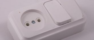
Switch instead of master button
The most basic load sharing is organized using an additional switch in the electrical panel. No, not like that