When installing a new or upgrading an old panel with a new circuit breaker, it is necessary to install a residual current device. The device protects the line from overloads, short circuits and prevents household appliances from breaking down. Some craftsmen cannot decide whether to install an RCD before or after the machine. Popular diagrams will help you choose the connection method.
Operating principle of RCD, differences from difavtomat
The requirements of the PUE indicate the need to install protective equipment. It provides protection against electric shock and breakdowns of the cable insulation coating. The RCD can be connected to 2 wires in a network with a voltage of 220 V and to 4 wires in a network of 380 V.
The disadvantage of the device is the inability to detect overload or short circuit. An automatic switch will further protect it. The difference between the devices is the response of the RCD to the current imbalance of phase and zero with a nominal value of 10-30 mA. The device does not recognize overcurrents and may even catch fire under their influence.
The difavtomat operates normally at a current of up to 16 A, and turns off the line in case of leaks. Unlike an RCD, it has a time-current characteristic, which determines the speed of shutdown.
A switch with an electromagnetic release trips when the current value exceeds 5-10 times.
Features of integrated operation of protective devices
To understand how to install an RCD - after or before the machine, you need to understand the functionality of the installation. A good example would be a system consisting of a metering device, a residual current device, or a circuit breaker connected to one line.
The voltage from the transformer will pass through the RCD and the meter, supplied to the sockets. If there is no protection, the shutdown device burns out. The absence of a release in front of the meter will also lead to a line fire. The best option is a protective device on both sides.
According to the requirements of the PUE, two-pole modifications of machines are placed before the metering device. There is no need to place it in front of it - it is better to protect the line from the RCD to the consumers.
Installing an RCD before or after the machine
The device responsible for disconnecting the line does not respond to overcurrents, therefore it does not operate in the event of short circuits and overloads. A joint connection with a difavtomat will prevent these situations.
Since the circuit current exceeds the rated current, the internal components of the device are damaged and the contacts burn out. Models without built-in protective elements must be installed together with circuit breakers that will eliminate the effects of overloads and short circuits. In this case, the current of the circuit breaker should not exceed the current rating of the RCD. For example, the latter reacts to 40 A. The optimal switch for it is 36 A.
Connection diagrams for RCD with switch
Protective equipment must be connected using two cables. The first will carry the load current, the second will be directed to the external circuit from the consumers. In order not to think about installing an RCD before or after the machine, you should use popular schemes.
For several groups of difavtomats - one RCD
Clause 7.1.79 of the PUE allows for the protection of several lines using an RCD. The device needs to be placed on top, then the switches on the consumer groups. In case of short circuits, the current passes through the RCD to the group circuit breaker, then to the power cable and to the consumer. If the rating of the devices is selected correctly, none of them will be damaged.
The advantages of implementing the scheme include saving money and space in the distribution panel. The downside of the connection is that all groups are disconnected after the RCD is triggered.
Installation of RCD to the machine
The diagram provides for installation in the following sequence:
- Safety shutdown device.
- Difavtomat.
- Power cord.
- Consumer.
If there is damage, the short circuit current passes through the RCD until the circuit breaker stops.
RCD after the machine
The system is assembled according to the principle;
- switch - two-pole or feeder;
- counter;
- RCD;
- machines depending on the number of lines.
This option is correct, since it is easy to understand how to turn off the machine and apply input to its terminals. Despite the fact that RCDs break more often, they are easier to replace.
At the moment of a short circuit, the current will pass from the switch to the RCD, then to the power wire, then to the consumer. The switch stops and the protective device remains intact.
To prevent overload, a second automatic circuit breaker can be installed between the meter and the RCD.
Connecting an RCD to a group of machines
A similar circuit is assembled in a three-phase switchboard, where there are:
- 3 three-phase difavtomat;
- three-phase RCD;
- 2 single-phase RCDs;
- 4 single-phase single-pole circuit breakers.
From the first input circuit breaker, the voltage will go to the second three-phase circuit through the upper terminals. From the same device, one phase will go to a single-phase RCD, the second to the next one.
Single-phase protection devices have two poles, difautomatic devices have one. In order for the system to work without failures, it is necessary not to connect the working zero after it. For this reason, a zero bus must be installed after each protective device.
If there are two-pole circuit breakers, a separate zero bus is not installed. When two zeros are combined, a false positive may occur.
The first single-pole RCD is connected to differential circuit breakers No. 1 and No. 3, the second - to No. 2 and No. 4. The load is applied to the lower terminals.
The grounding bus is common, but it must be installed separately. Three phases with a working zero are connected to the input device. It is connected to the common zero, and then diverted to all RCDs. After device No. 1 it goes to a three-phase load, after the remaining single-phase loads - to each bus.
The wire into PEN and PE is not separated - ground, zero and 3 phases go to the shield.
Where should the RCD be installed?
To determine where to install the residual current device, you need to remember the speed of current flow through the wires. It is equal to the speed of light - 300 thousand km/sec. In a standard C 16 machine, the turn-on time when passing currents of 5×In (80 A) will be 0.02 seconds. The distance it will cover is 6000 km.
In the event of a short circuit, the current will completely pass through the coupling device - RCD - cable - socket. In this case, the switch does not operate instantly, as a result of which the insulation melts and the socket contacts burn out.
The RCD does not fail, since a short circuit is an inertial reaction. A time of 0.02 seconds is simply not enough to melt the insulating coating and damage the parts. Even taking into account the breaking capacity, the protective devices will work properly regardless of the installation location:
- Automatic - RCD. The phase is supplied using a jumper, and the zero is supplied directly to the protective device. The wire for the sockets is connected to the device and the PE bus.
- RCD - automatic. The wire is connected to the sockets through different paths. The phase one goes to the machine, the zero goes to the protection device or the zero bus.
Thus, there is no difference where the RCD was installed - before or after the automatic device.
Machine denomination
On the body of any device the nominal value is indicated - the value of the maximum continuous current that passes through the device without harm. This parameter is safe for current switching.
To ensure protection of the RCD itself, it is necessary to install a circuit breaker with a rating similar to or 1 more than the rating of the device. If you have a machine with a rating of 16 A, the RCD should be about 25 A. This current reserve will be enough to prevent the flow of energy when the load increases.
The machine is triggered when a current appears 13% higher than the nominal value: a 16 A modification will operate at a current of 18 A. If the RCD rating is equal, the contacts may heat up. To select the rating of a system with several circuit breakers, you need to sum them up and select an RCD with a larger rating.
The nuances of installing a protective device
Connecting an RCD in an apartment or house requires compliance with several rules:
- For several groups of consumers it is necessary to install one RCD and individual circuit breakers.
- If there are several RCDs, each of them will need a zero output bus.
- The TN-C system does not need to be zeroed.
- For “wet groups” it is mandatory to install a protective device with a shutdown rating of 10 mA.
- 30 mA devices are suitable for household appliance outlets that operate with water.
- The zero terminal is located on the right side of the device and is marked with the letter N. It should not be confused with the phase (index L).
- Input can be made to the lower or upper terminals.
- The classic circuit is implemented using a top input and a bottom output.
- Each RCD requires a personal zero block to which all working neutrals are connected.
- For lines with ripple currents, type A devices are required.
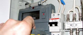
You can check the health of the system by pressing the “Test” button.
A protective shutdown device is needed to protect against overloads and short circuits. Due to the lack of response to overcurrents, it is installed in combination with a difavtomat. Connection diagrams allow installation of devices in any order. The only condition is the choice of the appropriate denomination.
Which comes first, ouzo or automatic?
I was prompted to write this article by a question asked to me for the hundredth time recently.
I admit honestly that you get tired of constantly answering the same thing. The essence of the issue is the correct sequence of connecting RCDs and circuit breakers. How to install an RCD correctly - before or after the machine? When I draw circuits to order, I receive comments that I have placed the RCD incorrectly and that it needs to be swapped with the machine, since the RCD can burn out from a short circuit current in the circuit. There were also similar remarks in the comments on this site. I have to waste time and write the same responses to such comments.
Therefore, I decided to write an answer to this question in the form of an article and in the future I will simply provide a link to this material as an answer. My personal reflections based on personal experience and acquired knowledge are written here.
Safety rules during work
Most of the rules are of a general nature, that is, they must be applied in the process of any electrical installation work.
If you decide to equip the electrical distribution panel yourself, before installing and connecting the RCD, do not forget:
- turn off the power supply - turn off the machine at the entrance;
- use wires with appropriate color markings;
- do not use metal pipes or fittings in the apartment for grounding;
- First of all, install an automatic input switch.
If possible, it is recommended to use separate devices for lighting lines, sockets, washing machine circuits, etc. Otherwise, installing a common RCD is sufficient.
To protect children, all electrical installations in a children's room are usually combined into one circuit and equipped with a separate device. Instead of an RCD, you can use a difavtomat
In addition to the characteristics of the devices themselves, the parameters of other electrical wiring elements are also important, for example, the cross-section of the electrical wire. It should be calculated taking into account the constant load.
It is better to connect the wires to each other using terminal blocks, and to connect to devices, use specially designed, marked terminals, as well as a diagram on the case.
How to properly install an RCD - before or after the machine
Let's look at different options for connecting RCDs to circuit breakers.
1. One RCD protects several group lines, i.e. it comes first and there are several circuit breakers installed after it. This diagram is presented below. It is very simple and popular in budget switchboards.
Let's now simulate an emergency situation. Let's say there is a short circuit in one group line. The diagram below shows the direction of movement of the short circuit current with a red line and arrows.
In this circuit, the current path will be as follows: RCD – group circuit breaker – cable to the socket – socket itself.
Many people believe that in this situation the RCD should burn out from the short-circuit current, since the machine is located after the RCD and simply cannot protect it from the action of a huge current. In fact, with this sequence of connection with the RCD, nothing bad will happen. Read below why this is so.
Here is a clear example of a switchboard, where several RCDs are in the first place, and group circuit breakers come after them.
2. The group line is protected by one machine and one RCD.
In the diagram presented below, the machine is already in first place, and the RCD is in second.
Here is a visual photo of this option. Here on the top DIN rail there are group circuit breakers, and below there is a row of RCDs that are connected to them. Each RCD is connected to its own machine.
Let's imagine an emergency situation with a short circuit in an outlet. The path of the short-circuit current in such a circuit will be as follows: machine - RCD - cable - socket. Look at the diagram below at the red line with arrows.
According to many people, in such a situation the machine should be triggered by a short circuit, thereby preventing the passage of destructive current through the RCD. And here I drew that the current reached the outlet. It turns out there is no connection and either I drew it incorrectly, or the current actually reaches the outlet and also flows through the RCD.
Let's figure out who is right and who is wrong. At what speed does current travel through wires? Let's remember physics and learn that the speed of propagation of the electromagnetic field is approximately equal to the speed of light - 300,000 km/s. Now let’s see how long it takes for the circuit breaker to trip when a short circuit current occurs. It fires in 0.02 seconds. We do a little calculation and find that in 0.02 seconds the current will have time to cover 6000 km. How far is your substation from your outlet?
From the above, we conclude that the short circuit current has time to run through the entire circuit of the circuit breaker - RCD - cable - socket. It’s just that the machine will not physically have time to operate instantly when a short-circuit current appears and stop it on itself.
Also, the fact that the short-circuit current reaches the socket is evidenced by a melted screwdriver, which short-circuited the wires in the socket and the burnt contacts of the socket itself. In order for a screwdriver to melt and the contacts at the socket to burn, something must act on them, since they cannot fail on their own. This is what the short circuit current does to them.
Then why doesn’t the RCD fail if a short circuit current flows through it? It does not fail because the cables going to the outlet, the electricity meter and other circuit elements encountered in the path of the short circuit current do not fail either. What is the danger from short circuit current? This is the appearance of high temperature, from which the insulation of cables and the housing of protective devices begins to melt. This process is inertial and the melting and combustion of the entire circuit requires some time, which the machine does not provide. Two hundredths of a second is not enough for the insulation on the cables to melt and for the RCD to burn out.
Therefore, we conclude that the RCD does not care where it stands - before or after the machine. It will feel good in both cases.
Then why in one circuit is the machine in front of the RCD, and in the other after? What is the difference?
Below is a diagram when one line is protected by one machine and one RCD. In the diagram on the left, the circuit breaker is in front of the RCD, and in the diagram on the right it is after the RCD.
In a pair of RCD + automatic circuit breaker, the automatic circuit breaker is always placed in first place due to the ease of installation and the simple connection of the cable from the load. See for yourself. If the machine is in first place (diagram on the left), then a “phase” comes from it via a jumper to the RCD, “zero” is supplied directly to the RCD. In this case, the cable going to the sockets is connected only to the RCD and to the PE bus. In the diagram on the right (the machine is located after the RCD), the outgoing cable to the sockets must already be connected to different protective devices - the “phase” to the machine, and the “zero” to the RCD. This is not convenient and the average person may get confused with connecting one cable. I believe that the task of a panel assembler is to competently assemble a circuit that will be most understandable to the user.
Therefore, if there is a pair of one machine and one RCD, then it is better to place the machine in first place. Of course, if you want to get confused, then choose the diagram on the right)))
Now let's see why if you need to connect several machines to one RCD, then the machines are always placed after the RCD. This diagram was presented above in the first connection option. What will we get if the machines are placed before the RCD? See diagram below. This turns out to be a completely incorrect and unworkable scheme. Therefore, remember that you cannot place several machines in front of the RCD.
It seems that we have sorted out the question of what comes first: RCD or automatic)))
Now let's at the same time see how to choose the right rating of the RCD so that it does not burn out from overload. On any RCD its nominal value is indicated, i.e. the maximum continuous current that can flow through the RCD without causing harm to it. Also, RCD contacts can switch this current painlessly, i.e. de-energize the line if a leak occurs in it. It is impossible to allow a current greater than its nominal value to flow through the contacts of the RCD, since its contacts will begin to heat up, the body will melt, etc.
Connection recommendations
Before connecting the ouzo to the power supply line along with distribution (linear) machines, the user should be reminded of a number of requirements for devices of this class by current regulations.
In general, they come down to instructions according to which the sequence and order of actions when installing an RCD are established
When considering these requirements, it is recommended to pay special attention to the following important points:
- In private houses with power equipment connected to a 380 Volt network, the installation of a three-phase protection device is required;
- To connect a three-phase ouzo, wires of the appropriate cross-section in insulation of different colors must be used;
Note! The color of insulating coatings is selected according to generally accepted standards. A visual representation of the choice of wire colors can be obtained in the figure below;
A visual representation of the choice of wire colors can be obtained in the figure below;
Wire colors by phase
To design the common (ground) terminal of a three-phase circuit, as a rule, a wire in blue insulation is used.
Taking into account all the above conditions, the connection procedure in this case can be represented by a list of recommendations and advice coming from specialists. Below are just a few of them:
- Protective devices are placed in their designated places only after the power line of the apartment or house is completely de-energized;
- Before connecting ouzo and automatic machines into a single electrical circuit, try to decide on the place intended for their installation on the instrument panel;
- It is recommended to choose it as close as possible to the electric meter installed on the input panel;
- The so-called “individual” RCDs, designed to protect a single supply line (bathroom, for example), must be used strictly for their intended purpose. They are not allowed to be installed after the meter as a general protective device for the apartment.
In the final part of the review, which covers the questions: why is an RCD needed, and how should it be connected to already installed equipment, we note the following.
When answering the question whether ouzo should be placed immediately after the counter, there is always a consonant statement. In this article you can also find out which ouzo to choose if the apartment has a given number of machines. We hope that after reading all the material presented, users will be able to independently understand the issues of installing protective devices in power circuits.
Operating principle of RCD, differences from difavtomat
The requirements of the PUE indicate the need to install protective equipment. It provides protection against electric shock and breakdowns of the cable insulation coating. The RCD can be connected to 2 wires in a network with a voltage of 220 V and to 4 wires in a network of 380 V.
The disadvantage of the device is the inability to detect overload or short circuit. An automatic switch will further protect it. The difference between the devices is the response of the RCD to the current imbalance of phase and zero with a nominal value of 10-30 mA. The device does not recognize overcurrents and may even catch fire under their influence.
The difavtomat operates normally at a current of up to 16 A, and turns off the line in case of leaks. Unlike an RCD, it has a time-current characteristic, which determines the speed of shutdown.
A switch with an electromagnetic release trips when the current value exceeds 5-10 times.
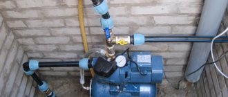
Where to install?
As a rule, the protective device is installed in an electrical panel, which is located on the landing or in the residents' apartment. It contains many devices that are responsible for metering and distributing electricity up to a thousand watts. Therefore, in one panel with an RCD there are machines, an electric meter, clamping blocks and other devices.
If you already have a shield installed, then installing the RCD will be easy. To do this, you will only need a minimal set of tools, which includes pliers, wire cutters, screwdrivers and a marker.
The process of installing automation in an electrical panel: step-by-step instructions
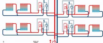
Let's consider the option of assembling an electrical panel for a one-room apartment; a switch, a protective multifunctional device will be used here, then a group of RCDs will be installed (type “A” for a washing machine and dishwasher, because such a device is recommended by the equipment manufacturer). After the protective device there will be all groups of circuit breakers (for air conditioning, refrigerator, washing machine, dishwasher, stove, and also for lighting). In addition, pulse relays will be used here; they are needed to control lighting devices. A special module for wiring will also be installed in the panel, which resembles a junction box.
Step 1: first, you need to place all the automation on the DIN rail, in the way we will connect it.
This is how the devices will be located in the panel
In the panel there is first a switch, then an UZM, four RCDs, a group of circuit breakers of 16 A, 20 A, 32 A. Next are 5 pulse relays, 3 lighting groups of 10 A and a module for connecting the wiring.
Step 2: Next we need a two-pole comb (to power the RCD). If the comb is longer than the number of RCDs (in our case, four), then it should be shortened using a special machine.
Cut the comb to the required size, and then install stops along the edges
Step 3: Now all RCDs should be fed together by installing a comb. Moreover, the screws of the first RCD should not be tightened. Next, you need to take cable sections of 10 square millimeters, remove the insulation from the ends, make crimping with lugs, and then connect the switch to the UZM, and the UZM to the first RCD.
This is what the connections will look like
Step 4: next you need to supply power to the switch, and accordingly to the UZM with the RCD. This can be done using a power cable, which has a plug at one end and two crimped wires with tips at the other. Moreover, you first need to insert the crimped wires into the switch, and only then make a connection to the network.
Next, all that remains is to connect the plug, then set the approximate range on the UZM and click on the “Test” button. So, you can check the functionality of the device.
Here you can see that the UZM is functioning, now you need to check each RCD (if connected correctly, it should turn off)
Step 5: Now you need to turn off the power and continue assembly - you should power the group of circuit breakers on the central rail with a comb. Here we will have 3 groups (the first is the hob/oven, the second is the dishwasher and washing machine, the third is the sockets).
We install the comb on the machines and transfer the slats to the panel
Step 6: Next you need to move on to the zero buses. There are four RCDs installed here, but only two zero buses are required, because they are not required for 2 groups. The reason for this is the presence of holes in the machines not only at the top, but also at the bottom, so we will connect the load to each of them, so a bus will not be required here.
In this case, you will need a cable of 6 square millimeters, which must be measured in place, stripped, clamped at the ends and connected to the RCD with its groups.
Using the same principle, it is necessary to power the devices with phase cables
Step 7: since we have already connected the automation, all that remains is to power the pulse relays. They should be connected to each other with a 1.5 square millimeter cable. In addition, the machine phase should be connected to the junction box.
This is what the assembled shield will look like
Next, you need to take a marker to mark the groups for which this or that equipment is intended. This is done in order to avoid confusion in case of further repairs.
Safety precautions when working with RCDs and automatic machines
Video - How to connect an RCD
Features of integrated operation of protective devices
To understand how to install an RCD - after or before the machine, you need to understand the functionality of the installation. A good example would be a system consisting of a metering device, a residual current device, or a circuit breaker connected to one line.
The voltage from the transformer will pass through the RCD and the meter, supplied to the sockets. If there is no protection, the shutdown device burns out. The absence of a release in front of the meter will also lead to a line fire. The best option is a protective device on both sides.
According to the requirements of the PUE, two-pole modifications of machines are placed before the metering device. There is no need to place it in front of it - it is better to protect the line from the RCD to the consumers.
Neutral and protective conductors
We have figured out the principles of operation of the RCD, all that remains is to carry out a correlation with existing alternating current power supply circuits. Most of the incidents related to the incorrect operation of differential protection devices are caused precisely by incorrect application in various power supply circuits.
Mainly, alternating current circuits differ in the presence and connection diagram of the neutral and protective conductors. Thus, it is possible to distinguish power supply circuits with a solidly grounded and isolated neutral. In practice, the difference lies in the place where the zero working and zero protective conductors are combined. For proper operation of the RCD, the common zero point must be located according to the diagram before the installation location of the device.
Circuits controlled by RCDs should not have the potential to dump part of the current to ground, otherwise false alarms are guaranteed. Therefore, leakage protection is predominantly provided to networks with an isolated neutral (IT and TT), that is, not connected to the protective neutral conductor along the entire length of the network after the ASU. The same category includes systems with solidly grounded neutral TN-S and TN-CS, although installing differential protection in them requires additional caution.
However, in TN-C type systems, residual current devices can still operate correctly. Their connection is made according to a 3- or 5-wire circuit, that is, the protective conductor is pulled to the distribution node to be combined with the working zero to the point where the RCD is inserted. Protection against differential current in this case is limited in selectivity: it is difficult to protect entire groups of conductors; devices can only be installed on the outer branches, that is, immediately in front of the current collectors. A particular example is sockets with built-in leakage protection.
Installing an RCD before or after the machine
The device responsible for disconnecting the line does not respond to overcurrents, therefore it does not operate in the event of short circuits and overloads. A joint connection with a difavtomat will prevent these situations.
Since the circuit current exceeds the rated current, the internal components of the device are damaged and the contacts burn out. Models without built-in protective elements must be installed together with circuit breakers that will eliminate the effects of overloads and short circuits. In this case, the current of the circuit breaker should not exceed the current rating of the RCD. For example, the latter reacts to 40 A. The optimal switch for it is 36 A.
How to connect
Installation of RCDs and automatic circuit breakers is carried out in the same way. When connecting wires to devices, you must follow the old rule.
Starting from the input machine to the last, you need to connect everything that is a load for this device to the lower contacts. Its output contacts, located on top, are connected to the input contacts of a device located in the circuit, higher in the hierarchy, if counted from the input machine.
Although some manufacturers' devices may work with any connection, following this connection order can reduce the number of errors when installing devices.
Connection diagrams for RCD with switch
Protective equipment must be connected using two cables. The first will carry the load current, the second will be directed to the external circuit from the consumers. In order not to think about installing an RCD before or after the machine, you should use popular schemes.
For several groups of difavtomats - one RCD
Clause 7.1.79 of the PUE allows for the protection of several lines using an RCD. The device needs to be placed on top, then the switches on the consumer groups. In case of short circuits, the current passes through the RCD to the group circuit breaker, then to the power cable and to the consumer. If the rating of the devices is selected correctly, none of them will be damaged.
The advantages of implementing the scheme include saving money and space in the distribution panel. The downside of the connection is that all groups are disconnected after the RCD is triggered.
Installation of RCD to the machine
The diagram provides for installation in the following sequence:
- Safety shutdown device.
- Difavtomat.
- Power cord.
- Consumer.
If there is damage, the short circuit current passes through the RCD until the circuit breaker stops.
RCD after the machine
The system is assembled according to the principle;
- switch - two-pole or feeder;
- counter;
- RCD;
- machines depending on the number of lines.
Selection of RCD by parameters
After the RCD connection diagram is ready, it is necessary to determine the parameters of the RCD. As you know, it will not save the network from overloads. And from a short circuit too. These parameters are monitored by the circuit breaker. To ensure the safety of all wiring, an input machine is installed at the entrance. After it there is a meter, and then they usually install a fire protection RCD. It is chosen specifically. The leakage current is 100 mA or 300 mA, and the rating is the same as that of the input circuit breaker or one step higher. That is, if the input circuit breaker is set at 50 A, the RCD after the meter is installed at either 50 A or 63 A.
The fire protection RCD is selected according to the rating of the input circuit breaker
Why a step higher? Because automatic protective switches operate with a delay. They can carry a current that exceeds the rated current by no more than 25% for at least an hour. The RCD is not designed for prolonged exposure to high currents, and is likely to burn out. The house will be left without electricity. But this applies to determining the rating of a fire protection RCD. Others are chosen differently.
Rated current
How to choose the RCD rating? It is selected according to the method for determining the rating of the machine - depending on the cross-section of the wire on which the device is installed. The rated current of the protective device cannot be greater than the maximum permissible current for a given wire. To make selection easier, there are special tables, one of them is below.
Table for selecting the rating of the circuit breaker and RCD
In the leftmost column we find the wire cross-section; to the right there is the recommended rating of the circuit breaker. The RCD should have the same. So choosing the rating of the leakage current protective device is not difficult.
Trip current value
When determining this parameter, you will also need an RCD connection diagram. The rated breaking current of the RCD is the value of the leakage current at which the power is turned off on the protected line. This parameter can be 6mA, 10mA, 30mA, 100mA, 500mA. The lowest current - 6 mA - is used in the USA, in European countries, and we don’t even have them for sale. Devices with a maximum leakage current of 100 mA or higher are used as fire protection. They are standing in front of the entrance machine.
For all other RCDs, this parameter is selected according to simple rules:
- Protection devices with a rated shutdown current of 10 mA are installed on lines that go into rooms with high humidity. In a house or apartment, this is the bathroom; there may also be lighting or sockets in the bathhouse, swimming pool, etc. The same shutdown current is set if the line powers one electrical appliance. For example, a washing machine, electric stove, etc. But if there are sockets on the same line, more leakage current is needed.
- An RCD with a leakage current of 30 mA is placed on group power lines. When more than one device is connected.
This is a simple algorithm based on experience. There is another method that takes into account not only the number of consumers, but also the rated current in the protection zone, or rather, the cross-section of the wire, since the rated current of the power supply line depends on this parameter. This is more correct, since it explains how to select the value of the leakage current for a general RCD, for example, and not just for devices that are installed on consumers.
Table for selecting the rated shutdown current for RCDs
It is also necessary to take into account the individual leakage currents of each device. The fact is that on every more or less complex device some small current “leaks away”. Responsible manufacturers indicate it in the specifications. Let’s say there is only one device on the line, but its own leakage current is more than 10 mA, install an RCD with a leakage current of 30 mA.
Monitored leakage current type and selectivity
Different instruments and devices use current of different forms, accordingly, the RCD must control leakage currents of different types.
- AC — alternating current (sinusoidal shape) is monitored;
- A - variable + pulsating (pulses);
- B - constant, pulsed, smoothed variable, variable;
- Selectivity. S and G - with a shutdown time delay (to exclude accidental operations), the G-type has a shorter shutter speed.
Selecting the type of leakage current to be monitored
The RCD is selected depending on the type of load being protected. If digital equipment is connected to the line, either type A is required. The lighting on the line is AC. Type B is, of course, good, but too expensive. It is usually installed in areas with increased danger in production, and very rarely in the private sector or in apartments.
RCDs of class G and S are installed in complex circuits if there are RCDs of several levels. This class is chosen for the “highest” level, then when one of the “lower” ones is triggered, the input protective device will not turn off the power.
Where should the RCD be installed?
To determine where to install the residual current device, you need to remember the speed of current flow through the wires. It is equal to the speed of light - 300 thousand km/sec. In a standard C 16 machine, the turn-on time when passing currents of 5×In (80 A) will be 0.02 seconds. The distance it will cover is 6000 km.
In the event of a short circuit, the current will completely pass through the coupling device - RCD - cable - socket. In this case, the switch does not operate instantly, as a result of which the insulation melts and the socket contacts burn out.
The RCD does not fail, since a short circuit is an inertial reaction. A time of 0.02 seconds is simply not enough to melt the insulating coating and damage the parts. Even taking into account the breaking capacity, the protective devices will work properly regardless of the installation location:
- Automatic - RCD. The phase is supplied using a jumper, and the zero is supplied directly to the protective device. The wire for the sockets is connected to the device and the PE bus.
- RCD - automatic. The wire is connected to the sockets through different paths. The phase one goes to the machine, the zero goes to the protection device or the zero bus.
Thus, there is no difference where the RCD was installed - before or after the automatic device.
Features of application
As you know, it is necessary to install a protective device in an electrical circuit precisely for the purpose of protection: as a result of a power surge or other emergency situations, it turns off the power using special technologies. As a result of such an operation, the technician will have to find the cause of the shutdown, which may include either a short circuit or a current leak. In the case of using RCBOs, such reasons may not be immediately detected.
But when using the “automatic device + RCD” combination, you will immediately see: if the RCD turns off, the fault lies in a current leak, but if the circuit breaker trips, then the reason is a short circuit or line overload.
Machine denomination
On the body of any device the nominal value is indicated - the value of the maximum continuous current that passes through the device without harm. This parameter is safe for current switching.
To ensure protection of the RCD itself, it is necessary to install a circuit breaker with a rating similar to or 1 more than the rating of the device. If you have a machine with a rating of 16 A, the RCD should be about 25 A. This current reserve will be enough to prevent the flow of energy when the load increases.
The machine is triggered when a current appears 13% higher than the nominal value: a 16 A modification will operate at a current of 18 A. If the RCD rating is equal, the contacts may heat up. To select the rating of a system with several circuit breakers, you need to sum them up and select an RCD with a larger rating.
Rail fixation and grounding
Although the range of electrical panels is large, they are all unified. To make installation as simple as possible, holes and mounting points are made in accordance with international standards. The lath is a strip of metal with a convex middle along its entire length.
The convex part is applied to the wall of the box and secured. Thus, two strips of metal are obtained, located at the same distance from each other and from the wall. Protection equipment can subsequently be installed on them.
On the back wall of all protective devices there is a special groove and a locking mechanism that allows you to securely attach it to the rail. To do this, you just need to put the device on the top strip and press the machine. The latch will lock it into place.
Installation occurs in the following sequence: RCD QD1, QD2, QD3, circuit breakers SF3, SF1, SF2, SF4, SF5. This arrangement will require less wire for internal installation.
At the bottom of the electrical panel there are places for fastening the neutral and grounding busbars. That's where they need to be secured. As can be seen from the installation diagram, three pads are used for the zero bus. This is necessary so that leakage currents are controlled separately in groups SF1, SF2 and SF4, SF5. After this, the devices are connected by wires to each other in accordance with the diagram.
The nuances of installing a protective device
Connecting an RCD in an apartment or house requires compliance with several rules:
- For several groups of consumers it is necessary to install one RCD and individual circuit breakers.
- If there are several RCDs, each of them will need a zero output bus.
- The TN-C system does not need to be zeroed.
- For “wet groups” it is mandatory to install a protective device with a shutdown rating of 10 mA.
- 30 mA devices are suitable for household appliance outlets that operate with water.
- The zero terminal is located on the right side of the device and is marked with the letter N. It should not be confused with the phase (index L).
- Input can be made to the lower or upper terminals.
- The classic circuit is implemented using a top input and a bottom output.
- Each RCD requires a personal zero block to which all working neutrals are connected.
- For lines with ripple currents, type A devices are required.
You can check the health of the system by pressing the “Test” button.
A protective shutdown device is needed to protect against overloads and short circuits. Due to the lack of response to overcurrents, it is installed in combination with a difavtomat. Connection diagrams allow installation of devices in any order. The only condition is the choice of the appropriate denomination.
Connection in an apartment and in a private house
For a washing machine,
the connection diagram in the apartment is carried out only via a single-phase network. For this reason, the connection is made in the following order:
Connection in the apartment
If you have power consumers of electricity in your apartment, for example, a washing machine or an electric oven, then it is recommended to additionally connect an RCD protective device.
As for connecting the machine in a private house, the connection sequence is as follows:
- Introductory machine.
- Electricity meter.
- Automatic from 100 to 300 mA, the choice is made depending on the amount of current consumed by all household appliances.
- Automatic machine for individual current consumption. Typically, 10 to 30 mA is used.
So, we have examined with you some of the features and differences of connecting an RCD in certain circumstances. Most importantly, remember that if you have no idea at all about this system, then it is better not to experiment.
A few words about typical errors when connecting an RCD:
To correctly install the RCD, we suggest that you familiarize yourself with some of its connection diagrams:
Residual current device
Connecting an RCD with automation
Connection to 380V network
Four-pole RCD without zero
Apartment group panel
1. Connecting a four-pole RCD to a three-phase network using a neutral. Your diagram shows a single-phase network. Above the green wire the inscription is blue. This wire should be yellow-green. 2. Connecting a four-pole RCD in a single-phase network. The figure shows a two-pole (single-phase) RCD.
Alexander! Thank you very much for your relevant comments. These shortcomings will be eliminated in the near future. We apologize for any inaccuracies in the illustrations posted.
- How to connect a washing machine with your own hands
- Instructions for replacing heating elements in a washing machine
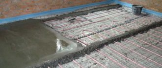
- How to make an electric heated floor
- Operating principle of the air conditioner
Video about installing electrical wiring yourself
Correct connection of the ouzo before or after the machine?
Friends, I welcome everyone to the “Electrician in the House” website. I think no one will doubt that in the present time, normal and safe operation of household appliances involves the use of modern residual current devices, circuit breakers, voltage relays, etc.
Today I want to address one question that has been frequently asked by readers of this site lately. The question is the correct sequence of connecting the RCD and the circuit breaker. Some readers are convinced that the RCD must be connected after the machine.
Others, on the contrary, justify their beliefs with design solutions, indicating power supply diagrams in which the installation of an RCD in front of the circuit breaker is clearly visible.
So who is right after all? Where to put the ouzo before or after the machine? We will deal with this issue today. I will try to analyze in detail all connection options.
Connection errors: how to avoid them
The question is often asked: how to connect an RCD correctly so that the circuit works without failures? As an answer, the following are the most typical miscalculations when connecting protective equipment without grounding.
- Interweaving of neutral conductors coming out of the device into a single unit. This provokes unreasonable alarms and makes it difficult to check the correct installation. To make sure that the assembly procedure without grounding is followed, plug the electrical appliance into the socket connected to the RCD. If it works, the circuit is assembled correctly.
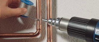
- Connecting the grounding wires of sockets to the neutral wire of the RCD or to a homemade grounding circuit. This violates electrical safety standards: an amateur circuit often causes a short circuit. When connecting the grounding switches of the sockets to water supply or heating pipes, an electric shock can strike not only the people living in the apartment, but also their neighbors.
- Neutral and ground connection. In this case, the RCD simply will not operate, since it works due to the difference in current strength in the phase and neutral wires. The connection between zero and ground provokes stable power outages in the apartment. If the grounding circuit does not work, then the grounding wires from the devices coming to the electrical panel should be wrapped with insulating tape: otherwise, the conductive parts of the household appliances may be exposed to dangerous voltage.
How to properly connect an RCD. demonstrates a video clip that details the sequence of all operations - thanks to the visual lesson, even a non-professional can easily cope with installing single-level protection. If the circuit is more complex, requires the coordinated operation of several protective devices, and is associated with a grounding connection, it is better to order installation by a professional electrician - so as not to be constantly without power and to operate electrical appliances safely.
Installation of ouzo before or after the machine
In fact, I believe that this question can be classified as a question of “which came first, the egg or the chicken”?
Let's figure out what the danger is? The danger is that the residual current device does not have overcurrent protection. If an overload or short circuit occurs in the circuit, the ouzo will not work, which is why it is connected in tandem with the machine.
The short circuit current can be hundreds of times higher than the rated current. It is easy to understand that nothing good should be expected when such large currents pass through the RCD. In this mode of operation, its internal parts may be damaged and contacts may burn out, and the device may simply lose its functionality.
And the sad thing about all this is the cost of the RCD, which is an order of magnitude higher than the cost of the circuit breaker.
IN THE OPINION of some readers, depending on where the residual current device is installed, it will depend on whether it is damaged or not. What can I say, I myself used to think that sequence matters.
In the apartment
Let's look at the case when the installation of protection equipment takes place in an apartment panel. Some builders, when delivering houses with an open plan, rent out housing without wiring the internal electrical network. This is understandable; it is not known where the partitions and, accordingly, sockets and lighting will be located. Therefore, they only introduce cable into the apartment.
On the floor electrical panel there is an introductory circuit breaker and an electric meter. The future owner enters into a contract with another contractor for internal electrical work. The wiring diagram will vary depending on customer requirements. It will depend on the circuit and the loads which RCD to install. If desired, any man can do this work on his own.
We will assume that the wiring in the apartment corresponds to the protection installation diagram presented in the previous figure. The input machine and counter are located in the floor panel, and all other elements will be located in the apartment box. To do this, you need to install an electrical panel in the corridor, next to the cable entry point. The sequence of work during installation is as follows:
- the input machine is turned off. A sign “Do not turn on, people are working” is posted;
- An outlet is connected to the cable that was brought into the apartment. It will be needed to connect working tools and lighting;
- the plate is removed, the machine is turned on;
- holes are drilled in the wall using a hammer drill for fastening the box. Dowels are inserted and the shield is attached to the wall with screws;
- after this, a metal strip is inserted and secured to the inner wall of the box with screws.
There shouldn’t be any difficulties if you perform all the steps consistently and carefully.
Connection diagrams for RCD with circuit breaker
Friends, to understand this issue, let's look at several diagrams for connecting an RCD and a circuit breaker. And in each connection option we simulate an emergency situation with the flow of short circuit current.
Connection option No. 1. One RCD for several groups of machines
With this connection scheme, one RCD protects several group lines. In this case, the residual current device is installed on top, and after it, circuit breakers are installed for different groups of consumers.
This scheme is very popular today and allows you to significantly save your budget.
| For those who think that it is impossible to connect like this, the rules of the PUE P.7.1.79 are quite acceptable. |
By the way, on the website Electrician in the House, I already told you how to make such connections. Read the article connecting an RCD to a group of machines. Now imagine the situation that a short circuit has occurred in one of the group lines. For example, in group No. 2. The figure shows the movement of the short-circuit current.
Here are some examples of the use of such circuits in electrical panels:
In this case, the short circuit current will flow along the following path: RCD - automatic circuit breaker of group No. 2 - supply cable - consumer.
Many will find this connection diagram incorrect, since the machine is located after the RCD and is not capable of eliminating the effect of short circuit current. A huge current will flow through the RCD, and it will definitely burn out. What do you think, will the RCD burn out or not? Take a break and write your opinion in the comments without reading the article to the end. Let's look further at the question of where it is necessary to install the ouzo before or after the machine.
Connection option No. 2. Installing an RCD upstream of the machine
This circuit is assembled in this way: residual current device – circuit breaker – power cable – consumer. That is, in this case, the RCD is installed before the machine . And such schemes are far from uncommon. Here are some assembly examples.
An example of the passage of short circuit current during a fault.
If a fault occurs, the circuit breaker will trip, but before this moment the short circuit current will have already passed through the RCD. For many users, this assembly method will also seem incorrect.
Connection option No. 3. Installation of RCD after the machine
With this connection scheme, the machine is installed first, and then the RCD. A clear example of such an assembly.
In the event of a short circuit, the current will flow along the following path: circuit breaker - RCD - power cable - consumer. This is indicated in the figure.
Again, for many, such a scheme will seem the most correct since along the path of the short-circuit current, the first thing that passes through the circuit breaker is that it will turn off in turn and the RCD will not be harmed in this case.
Two-phase electrical network: how to connect an RCD
First, it’s worth understanding why it is necessary to install protection in two-phase circuits. These are primarily observed in apartments located in old buildings, and in such conditions, additional safety is necessary, since more often in such housing there is no grounding, and current leakage in places where it should not exist often leads to a fire.
Let's talk about a single-level security system
The connection option is too simple at first glance, however, taking into account the nuances is important for complete safety
- The most powerful device is selected;
- The installation must provide for the transfer of current to the machine, and from it to all devices, including light bulbs and sockets;
- The design of this circuit is compact and elementary.
It is customary to install single-level protective devices on one device, too, for example, for a washing machine or water heater. To implement this method, a device with a power of 15 amperes is sufficient.
Scheme for connecting RCDs and automatic machines to the electricity meter
Let's turn to the question, like a machine gun, while implementing multi-level protection.
If a protected shutdown device is installed for individual areas, then we will talk about multi-level protection of a house or apartment. Typically, this diagram is for homes where grounding is present. In terms of price category, this option exceeds previous marks, and the devices are large in size. However, this system has such a significant advantage as the presence of autonomy for each individual household appliance. In the event of a short circuit in one of the devices, the entire living area will not be de-energized, but only the one in which there is a current leak from the network will cease to function. Here the connection to the electrical network changes; now there are as many cables coming out of the reading device as there are protection devices.
Today, RCDs and differential relays are often used, the connection diagram of which differs in that there is an absence of an automatic device. The general principle of connecting a system with a differential device is similar to the previous one, but the installation of additional current protection is provided.
Actions when turning off the machine
Inexperienced users, when the network is disconnected, automatically rush to restore the voltage supply by turning on the device. But it is not recommended to turn on the device without establishing the reason for the shutdown.
The machine may operate for the following reasons:
- overheating of sockets and switches as a result of loose contact;
- excess load due to the simultaneous activation of several powerful consumers;
- poor contact in wiring connections.
To determine the malfunction, you need to inspect your home network, make sure there is no heating or smell of burnt plastic. If the heating point is established, the necessary repairs are carried out.
When triggered by excess load, it is necessary to limit the number of switched on consuming devices. The device turns on after a complete check of the network and the cause of the shutdown has been eliminated.
The device may operate due to its failure, which is determined by visual inspection of the switch. If there is heating of the contacts, traces of thermal deformation, charring of the terminals, the machine must be replaced.
Serviceable and correctly selected circuit breakers will ensure normal operation of the home electrical network, eliminating the risk of damage to household appliances. But if the owner does not have electrician skills, it is worth contacting a qualified electrician to install or replace the machines.
Purpose and scope of RCD
The RCD is designed to compare the amount of electric current flowing in the phase and neutral wires. During normal operation of electrical appliances, this value is the same and the counter currents in the RCD windings compensate each other. As soon as an emergency situation occurs - the insulation is broken somewhere with the subsequent flow of charged particles to the ground, bypassing zero, the differential currents will differ and the protection will turn off the power.
But this does not mean that other equipment does not require similar devices for protective shutdown: the same lamps, sockets and other connected loads can also pose a threat to humans. Therefore, it is also important to connect them to the RCD on the panel, both common for all electrical wiring, and separately for any devices or their groups. Features of the use of electronic and electromechanical RCDs directly depend on the power supply circuit and the location of their installation.
What types of RCDs and differential circuit breakers are there based on the type of current leakage?
Electrical circuits use different types of currents, which is why protective devices are usually divided into classes:
- AC type. This is a common class of devices that have a budget price, so they are often used in apartments and country houses. They are calculated for the leakage of alternating current, on which most household appliances operate.
- Type A. Allows you to detect both AC and DC leakage. In recent years, manufacturers have begun to produce devices adapted specifically for such RCDs. Switching power supplies are used here to regulate power. Since these are more reliable devices, they cost a little more than the previous ones.
- Type B. These RCDs also react to any current leakage. However, they are often used only at production facilities and in public places. It makes no sense to install them in an apartment.
The marking by which the class is determined is located on the body of the device