Testing different composite beams
According to my project, I needed to assemble a composite beam that covers the span of a meter and will later be part of the rafters. The original lumber is a board 50*100*3000, dry, planed.
A mistake with a beam can be disastrous. I didn’t want to fall from a height of 2.5 meters onto the base sheathing. Therefore, after assembly, all beams were tested and the deflection in the center was measured under a static load of kilograms.
The first type of beam failed the test completely. Those. the deflection was more than centimeters. The mistake was that I used a meter-long central board.
Conclusions were drawn and I assembled a beam with a meter-long central board. Boards (2.2 m long) were attached to it on each side.
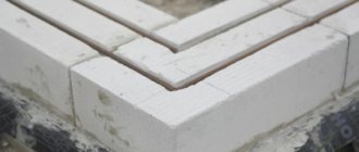
millimeter screws on each side were complemented by knitting needles:
The deflection in the center, with a static load of a kilogram, for this beam was 1.4 centimeters. I jumped on it and it seemed to hold it. Those. I already had a more or less working version, but I wanted more. Therefore, the next beam was assembled from boards (the first one was assembled). I screwed in the screws slightly away from the center. I only used two studs, which were additional fasteners for a short board on each side. The central part thus turned out without any joints at all:
The deflection of this beam was 1.3 centimeters. Those. I gained a whole millimeter compared to the previous type and greatly simplified the assembly.
Since such a drinking session was going on, I decided to try another version of the beam. Between the boards I laid galvanized sheet steel, 2.5 millimeters thick:
The image in my head suggested that the steel would prevent the wood from stretching under loads from above in the lower part and being compressed in the upper part. A sheet of steel tightly clamped between the boards will not curl.
The beam with metal sheets showed a record low deflection under static load - 1.1 centimeters. She resisted much more actively when jumping on it. The gain of a millimeter was not worth the effort and money spent on modification.
I decided to place the only beam with steel sheets in the middle of the roof. Perhaps, with heavier loads and longer spans, the use of sheet steel is justified. In my case, this is lordship.
But I didn’t stop there, the next day I assembled the beam, only I was fastening the boards not with millimeter screws, but with millimeter screws. The result of the deflection did not change and amounted to 1.3 centimeters.
So, in my case, to span a meter, using a meter board. It is best to assemble a beam from boards. solid, placed on top of each other, shifting each one 70 centimeters from the previous one. board, cut into pieces 1.4 meters long and delivered on both sides. Self-tapping screws - no less than millimeters.
When the beam is part of the rafters, it will bend even less. When you lay the floor on the ceiling and cover it with the ceiling below, the deflection will not be noticeable at all.
1) Izospan AP (70 sq.m) - 1,447 rubles 20 kopecks. 2) Self-tapping screw 5*100 - 300 pieces - 687 rubles. 3) Board 50*100*3000 (dry, planed) - 27 pieces - 5'572 rubles 80 kopecks. 4) Antiseptic, colorless, Olympus, 2.7 liters - 2 pcs. — 730 rubles. 5) Mounting angle 70*70*55 - 4 pieces - 126 rubles 72 kopecks. 6) Self-tapping screw 5*120 - 200 pieces - 578 rubles. 7) Galvanized steel sheet, 2.5 mm - 485 rubles.
The ceiling can be used regardless of what material the walls of the house are built from. You can make wooden floors with your own hands quite simply.
The attic and interfloor systems have almost the same design. The basis of such structures are beams, boards or panels. The ceiling is a load-bearing structure that is responsible for the strength of the floor, rests on the walls and subsequently evenly distributes the load on them. Most people prefer wooden material due to such indicators as strength, ease of installation and environmental friendliness.
Wednesday, April 18, 2012
Coverage No. 1: exercise in strength of materials
The first version of the basement floor (it’s also the floor of the first floor) was subjected to convincing criticism from knowledgeable people-practitioners (Ruslan, this is about you!). The main argument is that no one will ever guarantee the quality of 180×100 timber in Kyiv and the region: it may have internal defects, high humidity, etc., etc.
There is nothing to object to: an honest supplier is more the exception than the rule (this is how most businessmen in this part of the world work).
The solution turned out to be simple and obvious - instead of a 180x100 beam, it is better to assemble a beam from two boards (or beams too?) 180x50. The benefit is obvious: even if the wood turns out to be damp, it will dry faster while it waits for installation in place (say, about one month), and if in this case it turns out not to be dry enough, then in the process of further drying the knocked down boards will prevent each other from warping , i.e. a composite beam has a better chance of staying straight and level. In addition, if one of the boards included in the pair has internal defects and cracks form in it, then the second beam compensates for this deficiency (a solid beam is less insured against complete destruction).
So, at this stage, my floor beam from 180×100 timber (Fig. A) turned into a set of two 180×50 boards (Fig. B) and wrapping the ends with two layers of roofing material 1 m wide smoothly turned into laying the same two layers under the supporting part of the composite beam.
Wooden floors and their main characteristics
When making an interfloor ceiling, you should pay special attention to which room is located underneath. If the ceiling is located above the living space, then it is quite sufficient to use only noise insulating material. If the ceiling is located above a bathtub or toilet (or other room with a high level of humidity), it is worth taking care of high-quality thermal insulation and waterproofing.
The main characteristics of this design include the following:
- high level of heat saving;
- ease of installation work;
- high acoustic qualities;
- installation work can be carried out at any time of the year;
- wooden structures are used both as a floor between floors and as an attic floor.
General characteristics of wooden floors
The load on wooden floors is calculated from its own weight and other additional loads. On average, the dead weight of a wooden system is 230 kg per 1 m². For additional loads, a value of up to 200 kg is provided. In order to determine the distance that needs to be placed between beams, it is worth taking into account the main indicators: span length, what loads are provided on the floor, characteristics of the beams. On average, the step between beams should not exceed 1 m.
- the thickness of the beam should not be less than 5 cm;
- The height of the beam is most often 15 cm;
- If the beams are laid at a distance of 50 cm from each other, it will be easy to lay mineral wool or other thermal insulation material between them.
There are also tables, thanks to which you can calculate and select the required beam much faster.
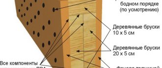
For manufacturing, you can use boards whose thickness is at least 60 mm; round timber can also be used. An alternative option is to use 2 boards 50 mm thick, which are fastened together with nails. But experts recommend using such options for the design of the box. The finished beams are subsequently lined with boards on 1-2 sides, depending on certain criteria.
Hemming the ceiling
The next stage is extremely simple: a hemming board of arbitrary thickness is placed on the lower shelves of the wooden I-beam, which is fixed in any way. Boards can also be laid with a gap, using the rough backing as a support for thermal insulation, especially when it comes to dense materials like stone wool or EPS. This will slightly reduce the dead weight of the ceiling.
The boards should not be fitted too tightly; leave a gap of 3–5 mm for deformation during drying. If you want to immediately lay the lining under varnish, leaving the beams open, take the trouble to insulate the insulation from spillage and weathering, leave a gap at the ends of the slats of at least 2-3 mm.
You can also refuse to lay boards like this and hem the ceiling with, say, chipboard. However, the described approach allows you to avoid downtime: after all, the finished ceiling is not installed quickly, and the ceiling must be used.
Do-it-yourself ceiling: preparatory work
In order to begin installing the interfloor structure, you first need to prepare the beams. It is very important that the humidity of finished products does not exceed 20%. The bark on the material must be removed. After cleaning, the beams are treated along their entire length with special antiseptic agents and fire-fighting impregnations. More expensive materials are systems that have undergone a full range of processing under production conditions.
In order to make a ceiling with your own hands, you should prepare all the necessary tools:
- keys of different sizes;
- anchor bolts;
- staples;
- metal corners;
- screws of the appropriate size;
- screwdriver;
- nails;
- wood saw;
- rope;
- ladder or stepladder;
- axe;
- water level;
- tape measure and pencil for marking.
Very often, glued laminated timber no more than 12 m long is used for installation.
This type of material is considered the most practical and reliable today. In addition to high quality indicators, such timber can be made to order and have different sizes, which will minimize the amount of waste.
Photo report
we make a strip of plywood slightly narrower than a board
We saw several slabs at once, having previously leveled them. The last slab is sawed just a little from the top - the finished markings.
Cheap quick-release clamps almost immediately went into the trash, they were too weak. The usual screw F-shaped ones have replaced them.
When trying to pull out a 150 nail that got caught on a knot, the hammer couldn’t stand it
The intermediate fastening points are marked with a marker. So that when attaching the next layer, you don’t get caught in the fasteners on another.
I went over the beams on top with a plane so that the surface was even.
The beams are placed on edge and the strapping is ready
After making all the beams, we make half-beam cuts in the corners, assemble the perimeter, check the diagonals and attach them to the heads. I must say that due to the dry wood, the beams turned out to be very light. All work was done by one person. It is of course unrealistic to lift and move such a beam alone, but turning it over or moving it by lifting it by the end is quite possible.
The error of the diagonals turned out to be 5-7mm.
What comments can I make about the beam after the fact?
- It only makes sense to use glue if you have planed boards of ideal geometry. Otherwise, it is extremely difficult to tighten the beam so that the glue works. Considering that glue is not cheap and you need a lot of it, I think it makes sense to abandon it. I repeat, this applies to the case when the beam is assembled from a dry, unplaned board. If the board is naturally damp, then the glue is completely useless.
- Having already made the beams, I came across an American article where the advantages of a beam assembled with and without plywood were discussed. The general conclusion is that plywood gives an increase in strength of approximately 15%. Moreover, increasing the height of the board gives a greater increase in strength. In other words, a beam made from a 40x200mm board without plywood will be stronger than a 40x150mm beam with plywood.
- Punching through the entire sandwich with 150mm nails is quite difficult. It makes sense to punch 90mm nails in layers (2 boards each)
Stages and features of the work
Work must begin with laying the load-bearing bars, which are located along the edges. Further laying is carried out towards the center. During work, it is very important to control the distance between the beams.
When laying all beams, it is necessary to check the horizontal plane using a building level. Unevenness can be eliminated by placing boards under one end of the beam. It is very important to treat such boards in advance with special protective agents.
In order to lay beams, when constructing walls on the outside, nests are left, the depth of which is 15-20 cm. To make the structure as reliable as possible, every 3rd part must be secured with anchors.
In addition, in order to increase resistance to various rotting processes, the ends of all beams must be coated with bitumen mastic and wrapped in several layers of roofing material. Thanks to this method of protection, they will last much longer.
After the roll is made, the space that is formed between the beams must be filled with sound and heat insulating material.
On top of the flooring you can lay slabs of mineral wool, extruded polystyrene foam, and expanded clay concrete. If the insulation is laid in the attic, it can be covered on top with a layer of clay-sand grease, the thickness of which should be 2-3 cm. It will significantly help increase the thermal insulation qualities of the material.
After all the thermal insulation layers have been placed, it is necessary to lay a reinforcing mesh on top, on top of which the screed is poured. This will later be the basis for the flooring. If the ceilings are created for the attic, then they can be made from tongue and groove boards.
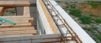
According to my project, I needed to assemble a composite beam that would cover a span of 4 meters and would later be part of the rafters. The original lumber is a board 50*100*3000, dry, planed.
A mistake with a beam can be disastrous. I didn’t want to fall from a height of 2.5 meters onto the base sheathing. Therefore, after assembly, all beams were tested and the deflection in the center was measured under a static load of 75 kilograms.
The first type of beam failed the test completely. Those. the deflection was more than 10 centimeters. The mistake was that I used a meter-long central board.
Conclusions were drawn and I assembled a beam with a 3-meter central board. Two boards (2.2 m long) were attached to it on each side.
12 76 mm self-tapping screws on each side complemented 6 knitting needles:
The deflection in the center, with a static load of 75 kilograms, for this beam was 1.4 centimeters. I jumped on it and it seemed to hold it. Those. I already had a more or less working version, but I wanted more. Therefore, the next beam was assembled from 4 boards (the first of 5 was assembled). I screwed in the screws slightly away from the center. I only used two studs, which were additional fasteners for a short board on each side. The central part thus turned out without any joints at all:
The deflection of this beam was 1.3 centimeters. Those. I gained a whole millimeter compared to the previous type and greatly simplified the assembly.
Since such a drinking session was going on, I decided to try another version of the beam. Between the boards I laid galvanized sheet steel, 2.5 millimeters thick:
The image in my head suggested that the steel would prevent the wood from stretching under loads from above in the lower part and being compressed in the upper part. A sheet of steel tightly clamped between the boards will not curl.
The beam with metal sheets showed a record low deflection under static load - 1.1 centimeters. She resisted much more actively when jumping on it. The gain of 2 millimeters was not worth the effort and money spent on modification.
I decided to place the only beam with steel sheets in the middle of the roof. Perhaps, with heavier loads and longer spans, the use of sheet steel is justified. In my case, this is lordship.
But I didn’t stop there, the next day I assembled the beam, only I fastened the boards not with 76 mm screws, but with 120 mm ones. The result of the deflection did not change and amounted to 1.3 centimeters.
Thus, in my case, for a span of 4 meters, using a 3 meter board. It is best to assemble a beam from 4 boards. 3 solid ones, placed on top of each other, shifting each one by 70 centimeters from the previous one. The 4th board is cut into 2 pieces 1.4 meters long and delivered on both sides. Self-tapping screws - at least 76 millimeters.
When the beam is part of the rafters, it will bend even less. When you lay the floor on the ceiling and cover it with the ceiling below, the deflection will not be noticeable at all.
1) Izospan AP (70 sq.m) - 1,447 rubles 20 kopecks. 2) Self-tapping screw 5*100 - 300 pieces - 687 rubles. 3) Board 50*100*3000 (dry, planed) - 27 pieces - 5'572 rubles 80 kopecks. 4) Antiseptic, colorless, Olympus, 2.7 liters - 2 pcs. — 730 rubles. 5) Mounting angle 70*70*55 - 4 pieces - 126 rubles 72 kopecks. 6) Self-tapping screw 5*120 - 200 pieces - 578 rubles. 7) Galvanized steel sheet, 2.5 mm - 485 rubles.
Total: 9'626 rubles 72 kopecks.
The basement floor (aka the floor of the first floor) was subjected to convincing criticism from knowledgeable people-practitioners (Ruslan, this is about you!). The main argument is that no one will ever guarantee the quality of 180×100 timber in Kyiv and the region: it may have internal defects, high humidity, etc., etc.
There is nothing to object to: an honest supplier is more the exception than the rule (this is how most businessmen in this part of the world work).
The solution turned out to be simple and obvious - instead of a 180x100 beam, it is better to assemble a beam from two boards (or beams too?) 180x50. The benefit is obvious: even if the wood turns out to be damp, it will dry faster while it waits for installation in place (say, about one month), and if in this case it turns out not to be dry enough, then in the process of further drying the knocked down boards will prevent each other from warping , i.e. a composite beam has a better chance of staying straight and level. In addition, if one of the boards included in the pair has internal defects and cracks form in it, then the second beam compensates for this deficiency (a solid beam is less insured against complete destruction).
It follows that a slight increase in height is much more effective in terms of strength than increasing the width of the beam.
A common misconception is that inserts between boards (Fig. D) increase the width of the cross-section. In fact, only the solid components are taken into account in the geometric characteristics of the beam cross-section. Therefore, two 180×50 boards glued and tightly knocked together (Fig. E), or placed side by side, but not attached to each other (Fig. E), or spaced at a decent distance (Fig. G) will provide strength exactly also as connected through spacers (Fig. D), or as four 180×25 boards (Fig. H), or as five 180×20 boards (connected or disconnected), and ultimately as 180×100 timber.
The vertical connection of the components of a composite beam (Fig. B and D) is justified only in special structural cases. For example, to neutralize the curling of the boards when drying or to ensure the stability of the component parts - in other words, if you suddenly decide to assemble a beam from twenty 180x5 boards, then any of them can “fold” in height under load, so you will have to fasten them together .
I “played around” a little with the cross-sectional dimensions and settled on a design consisting of two 200×40 boards (i.e. 200×80, see the picture on the right), which turned out to be more advantageous in many respects compared to 180×50×2 and, even more so, better than 180x100 mm (for which, in fact, everything was started).
Surely, a board 40 mm thick will dry even faster than 50 mm. The boards will be tightened in pairs with large self-tapping screws solely for the purpose of combating shrinkage deformations that may occur when the wood dries. Among other things, there is a suspicion that an edged board with a width of 200 mm may turn out to be cheaper and more accessible than 180 mm - some experts consider the size of 180 mm to be non-standard.
In places where additional strength is required (internal walls, partitions, the base of an interfloor staircase), the beams are made up of three 200x40 boards.
And finally, dispassionate, but the most convincing figures - a comparative table of beams: the first option (180×100) and the last option (200×80, or 2×200×40) with a load of 400 kg/m²:
| 180×100 | 200×80 | 2×180×100 | 3×200×40 | |
| deflection at 0.5 m step (max. 15 mm) | 9 | 8 | 5 | 6 |
| relative deflection at 0.5 m step (max. 1/250) | 1/403 | 1/454 | 1/726 | 1/605 |
| deflection reserve at a step of 0.5 m | 1,67 | 1,88 | 3 | 2,5 |
| deflection at 0.6 m pitch (max. 15 mm) | 11 | 10 | 6 | 7 |
| relative deflection at 0.6 m step (max. 1/250) | 1/330 | 1/363 | 1/605 | 1/519 |
| deflection reserve at a step of 0.6 m | 1,36 | 1,5 | 2,5 | 2,14 |
| deflection at 0.7 m pitch (max. 15 mm) | 13 | 12 | 6 | 8 |
| relative deflection at 0.7 m step (max. 1/250) | 1/279 | 1/303 | 1/605 | 1/454 |
| deflection reserve at a step of 0.7 m | 1,15 | 1,25 | 2,5 | 1,88 |
| 2618 | 2586 | 5236 | 3879 | |
| own weight (kg) | 35 | 31 | 71 | 47 |
| material savings (%) | → | 11 | → | 33,8 |
Thus, a 200×80 beam (or two 200×40 beams) in all respects exceeds the strength characteristics of a 180×100 beam (or a 2×180×50 composite beam, which is the same thing). Double beams (two 180x100 each), of course, surpass in their characteristics the “one and a half” beam 200x120 (actually 3x200x40), however, the double (and sometimes more!) deflection reserve of this “one and a half” beam is quite sufficient. But what a saving in material...
We continue to look at articles on the topic of how to make a frame from boards with your own hands. We looked at the installation of the lower and upper framing of the frame, as well as the assembly and installation of vertical posts, now we will continue to consider the assembly and installation of ceiling beams and jibs. We have a span of ceiling beams of more than 6 meters; there is a need to make another beam for the ceiling and floor, which will be perpendicular to all the other beams.
What a strange material
The technology for assembling I-beams is quite simple. Imagine a board with conventional dimensions of 25x80, having one or more longitudinal grooves. Two such boards are oriented parallel with grooves facing each other. Rectangular OSB plates are inserted into the grooves, the product is glued and possibly filled with polyurethane. Here is an example of an interesting and bold technological solution, aimed mainly at insulating roofs and ceilings without cold bridges.
It would seem, why complicate everything and abandon the natural strength of solid and laminated timber? Because the use of beams has a number of advantages: faster installation, ease of use, fairly high-quality insulation of structural and airborne noise. When used correctly, these advantages cover the relatively high cost of the material; moreover, due to the orientation of the fibers of the central flange, a wooden I-beam is comparable in reliability to solid wood.
Installation of ceiling and floor cross beams.
In Figure 1, it can be seen that a partition is provided in the place where the beam is located.
The cross beam in Figure 1 is shown in red.
Fig 1. Plan with the location of the ceiling beams (transverse and longitudinal)
At ceiling level, this cross beam rests on the partition studs, and the partition studs rest on the floor cross beam. We will consider the structure of these two transverse beams (floor and ceiling) below.
Fig 2. Ceiling cross beam
The ceiling cross beam is attached to the partition posts. In the upper part, at the ends of the cross beam, a cut was made under the top trim, so that the top of the cross beam coincides with the top of the trim. This is done so that the longitudinal ceiling beams rest with one end on the cross beam and the other end on the trim. At the same time, at the junction of the ceiling cross beam with the frame, the cross beam does not rest on the load-bearing wall post. It (the ceiling cross beam) rests entirely on the partition posts, Figure 2.
In turn, the partition posts have cuts for this beam (the cuts are visible in Figure 2), and the partition posts themselves rest on the same transverse floor beam. After installing the floor and ceiling cross beams, the joists will be laid on the floor cross beam. And the ceiling beams will rest on the cross beam of the ceiling. Since there was no foundation for the partition, the transverse floor beam was laid on brick columns (Figure 3). The posts are located directly under the posts; the partition posts are installed at intervals of 1200 mm. The size of the span between the racks was chosen based on two points:
Fig 3. Transverse floor beam on brick columns
You can read how to make brick columns in the article “Preparatory work for laying floors on joists.” We do not consider laying joists on a transverse floor beam in this article; you can read about this in the article “Laying a floor on joists.”
We make the transverse floor beam so that the floor joists will subsequently lie on it without cuts. As can be seen in Figure 3, the floor cross beam is made of several bars held together with self-tapping screws. The bars are 50*70 mm, 5 bars are taken, the total width of the floor cross beam is 250 mm, the height is 70 mm.
Connection and docking
There are quite complex floor configurations in which beams can be joined to increase the length or connected at right angles to form lintels. The beams of the main span should not be joined outside the load-bearing walls or columns, but in some cases this may be necessary, for example, when the ceiling extends into a bay window niche.
To connect beams to one of them, it is necessary to cut the shelves at least 4 times the height of the beam. The central post is cut to the same distance and the groove on the other side is cleaned. The beam is spliced and, if possible, glued with casein glue with the obligatory installation of a pressure of 2–2.5 kgf/cm2. After drying, the joint on both sides is strengthened with butt plates - one or more 25 mm boards, well fitted between the shelves. The overlays are tightened together with self-tapping screws and screwed to the outer shelves in increments of 20 cm.
For rectangular connections, special steel brackets should be used. The flanges of the adjacent beam must be cut to the depth of entry, while the beam to which the connection is made must remain intact. As for consumables for fastening, you will find them in abundance from manufacturers and distributors of beams, as well as methods for calculating floors, rafter systems and walls, as well as more specific connection methods.
Installation of longitudinal ceiling beams.
After installing the cross beam of the ceiling, we install the longitudinal beams of the ceiling.
Fig 4. Longitudinal beam of the ceiling
The material for the longitudinal beams is the same board, 50 mm thick and 150 mm wide. At the ends of the longitudinal beams resting on the external walls, we make a 50/50 cut under the top beam (visible in Figure 4). And we simply fasten those ends that lie on the cross beam together using a piece of board and attach them to the cross beam with a metal corner (a little visible in Figure 5).
Fig 5. Extreme ceiling longitudinal beams attached to the beam
The distance between the longitudinal ceiling beams is 1200 mm to match the size of the rolled thermal insulation. We will arrange these beams in such a way that not a single beam stands above the window opening; for this, the step in some places will have to be made a little less, and in some places a little more.
Important: if there is a residential floor above the ceiling, you often walk on the ceiling, store some things in the attic, then with spans like ours at 4 meters and 150 mm thick boards, the step needs to be made smaller - 600 mm or add beams later.
The outer longitudinal beams of the ceiling are attracted with self-tapping screws to the side of the beam, so that they become in the same plane with the wall. The protrusion of the beams beyond the external wall was provided at 300 mm, as can be seen in Figure 6.
Fig. 6. Ceiling beams protrude 300 mm beyond the load-bearing wall
My ceiling beams also serve as a support for the rafters, which is why the 300 mm protrusion is made. To install rafters on them, a 5050 mm block was placed on top of the ends of the beams with a distance of 50 mm from the edge (Figures 7 and 6).
Fig 7. Block for installing rafters
Calculations
Calculation of the cross-section will allow you to have no doubt about the strength and rigidity of the structure. In this case, the maximum length that is allowed for any section is determined. To perform the calculation, you need the following data:
- the length of the wooden floor beam (more precisely, the distance between the load-bearing walls);
- the distance between the beams (their pitch);
- load on the structure.
To calculate, you need to know the distance between the beams, the width of the span and the load on the structure
The load consists of two values: permanent and temporary. The permanent includes the mass of the beams themselves (preliminary for now), insulation, ceiling lining, rough and finished floor. The temporary load is the mass of people and furniture. According to regulatory documents for residential premises, it is taken to be 150 kg/m2. For the attic you can take less, but it is recommended to use the same one. This will not only provide a certain margin of safety, but will also make it possible in the future to convert your attic into an attic without reconstructing the load-bearing elements.
The beam frame should be calculated using the following formulas:
In these formulas, q is the load per square meter. m of flooring, which includes the mass of structures and 150 kg of useful value. In this case, these values must be multiplied by the distance between the beams. This is due to the fact that the calculations require a load per linear meter, and initially the value was calculated per square meter. l2 is the distance between the load-bearing walls on which the purlin rests, taken in a square.
Knowing Wrequirement, you can select the section of the floor. W = b*h2/6. Knowing W, you can easily create an equation with one unknown. Here it is enough just to set one geometric characteristic b (section width) or h (its height).
Most often, the wooden beam already has a known width. It is more convenient to make it from a board 50 or 100 mm wide. You can also consider the option with a composite section. It is made from several boards 50 mm thick.
By calculation in this case, the required height of the element is found. But there are cases when you need to fit into a certain ceiling pie so as not to reduce the height of the premises. In this case, the height of the section is added to the equation as a known quantity, and the width is found. But the lower the height, the more uneconomical the floor frame will be.
To tighten two or three boards together, it is convenient to use metal pins. In this case, when tightening the nuts, be sure to use wider washers. They prevent the metal from pressing into the softer wood. It is imperative to provide insulation between wood and steel fasteners. For this, you can use a material such as TECHNOELAST brand EPP.
Wooden blocks must be waterproofed before installation
Before using wooden elements, they are treated with an antiseptic composition. This is necessary to prevent mold and rot. It is also recommended to treat with fire retardants, which will increase fire safety. When resting the purlins on a wall made of brick or concrete, their ends are wrapped with technoelast, linocrom, waterproofing or roofing felt.
chronicle of the “reign” on 10 acres near Kiev
Design and installation of permanent jibs.
At the same time, permanent jibs are made on the walls, thus:
We apply a board 100 mm wide and 25 mm thick to the wall studs and trace it with a pencil. Then we make cuts in the racks and use a chisel to make indentations in them.
Fig. 8. Notches in racks for jibs
Then we screw the same board onto the mounting foam with self-tapping screws.
Fig. 9. Installation of permanent jibs
Fig. 10. Installation of permanent jibs
Key points to consider when locating and installing permanent jibs:
Figure 11. Frame posts with permanent jibs
In the next article in the series “Do-it-yourself frame from boards.” Assembly and installation of the rafter system, we will tell you about the assembly and installation of the rafter system.
Korovin Sergey Dmitrievich
Master of Architecture, graduated from Samara State University of Architecture and Civil Engineering. 11 years of experience in design and construction.
Wooden floor beams provide not only the strength of the horizontal structure. The purpose of the ceiling is to provide rigidity to the entire building. It is for this reason that special attention should be paid to the selection of load-bearing elements and their installation.
Pros and cons of wooden floors
To install the ceiling yourself, you need to prepare. The floor in the house must rest on a strong and rigid structure. Before starting work, you will have to study the requirements for the elements, the features of their calculation and the types of sections.
The following advantages of wooden flooring can be highlighted:
- attractive appearance, the ability to make a wooden floor without additional measures;
- light weight, reduced load on walls and foundations, savings on construction;
- possibility of carrying out repairs during operation;
- speed of installation, execution of work without additional machines and mechanisms.
Wooden beams do not weigh down the structure and are quickly installed
But it is also worth highlighting the disadvantages:
- flammability of wood, the need for special impregnation with fire retardants;
- lower strength compared to reinforced concrete or metal elements;
- shrinkage and deformation due to changes in temperature and humidity;
- susceptibility to rot, mildew and mold at high humidity, it is necessary to treat with antiseptics at the construction stage and periodically during the service life.
Definition of the concept
The ceiling is a load-bearing horizontal structure that divides the building in height. Its main function is to distribute the load. The beam is the main support; it holds the entire structure of the building together and provides the necessary rigidity.
Application area
Beam wooden floors are used in:
- houses on summer cottages, designed for use in the summer;
- frame and log buildings made of wood;
- prefabricated prefabricated buildings;
- buildings for economic purposes - workshop, bathhouse, barn, utility block.
If the strength of the foundation is not designed for heavy floors, then wooden beams are usually placed between floors in houses made of brick or gas silicate blocks.
Requirements for wooden floors
Wooden floor beams must meet the following requirements:
- correspondence of section dimensions to load, span and pitch, this requires calculation of beams;
- good strength and rigidity;
- Fire safety;
- no serious wood defects or damage.
For work it is necessary to prepare high-quality material
There are also certain requirements for the material from which the beams are made. It is recommended to choose coniferous wood. It contains a lot of resin, so it is better resistant to various microorganisms . The best material is considered to be those trees that have grown in harsh conditions. Their trunk density is higher. For this reason, it is worth purchasing pine or spruce that grew in the northern regions of the country.
You also need to pay attention to the preparation time. The best period is considered to be at the end of winter. At this time, the tree is in a dormant state, there is less juice in it, and therefore the moisture content of the material will be less.
GOSTs and SNiPs for I-beams
The use of supporting products in construction is regulated by state standards and regulations.
In this case, the following documents have been developed and applied:
GOST 30244-94. "Building materials and components."
SNiP 2.08.01-89. "Houses for living."
GOST 8486-86E. “Specifications for materials of species from coniferous trees.”
SNiP II-25-80. "Wood structures".
In the manufacture of wooden beams, materials from coniferous trees are used in accordance with GOST 8486.
GOST 8486. Production of cranial blanks from coniferous material.
GOST 2695. 1.3.2. Hardwood timber (alder, aspen).
SNiP II-25. Design parameters of beam wood, and it must be at least 2nd grade. For cranial bars it is allowed to use grade 3 wood.
What types of wooden floors are there?
Wooden floor beams are used for almost all levels of the house. The beam frame must be provided for the following types of construction:
- basement or basement floor (first floor floor);
- interfloor covering;
- attic floor.
The thickness of the supporting beam for the attic is from 10 to 20 cm
The normalized payload, which is taken into account in the calculation of wooden floor beams, depends on the type. There will also be a difference in the thickness of the insulation and its necessity.
Between 5 and 15 cm of mineral wool, polystyrene foam or extruded polystyrene foam is usually laid between the beams above the basement. In interfloor structures, it will be enough to provide a couple of centimeters for sound insulation. A cold attic requires the most material. Here the thickness can be from 10 to 20 cm. The exact values depend on the climatic region of construction.
Sometimes they prefer to make the basement floor not from wood, but from metal and reinforced concrete. In this case, an I-beam or channel is used as load-bearing beams, and concrete is poured into formwork made of corrugated sheets. This option will be more reliable if there is a risk of flooding. It will also better resist moisture from the basement.
Features of I-beams
The main feature of products of this type is that they are made in the form of a horizontal beam, which, with a schematic representation of the thickness (section), in section, resembles a beech T on a substrate , or, if you turn the beam in the other direction, a thick letter H. Also, the appearance of some experts consider it vaguely similar to rails.
The shape of the products in the form of the letter H is made for ease of installation of various types of structures in which I-beams play an important reinforcing and load-bearing role. But they are of particular importance as one of the elements of the foundation of the floors of any structure being built.
The standard size of an I-beam is: 14.0 x 73 x 7.5 (cm) , but there are other varieties.
Each product has its own marking, in the form of alphanumeric designations. I-beams have good quality characteristics, the most important of which are strength, stability and the ability to support load-bearing structures.
In construction, beams are resistant to high loads and external manifestations of atmospheric changes . They also do not respond to mechanical stress, have high compression density, and ideally adhere to various types of substances. The listed features allow the products to be used in the construction of structural elements of frame buildings and structures.
I-beams are widely used not only in the construction of private houses, but also in the construction of industrial buildings. The products are indispensable when working with reinforced concrete slabs, stairs, spans, and roofing.
I-beams are light in weight, which is convenient for transportation and installation. For fastening materials, angles, anchors, rivets, bolts, welding, metal hooks, and logs are used.
What types of beams are there?
There are several criteria by which wooden floor beams are classified: by size, material, type of section. The length of the floor beams depends on the distance between the walls. To this value you need to add a margin for support on both sides . Optimally, you need to provide 200-250 mm.
Based on material, elements are divided into the following types:
- from solid timber or boards;
- from laminated veneer lumber.
Bent beams are made from laminated veneer lumber
The latter are significantly more expensive. But such material is suitable for covering large spans. A regular beam can work at distances of 4-6 m, while a laminated beam copes well with distances of 6-9 m. Glued laminated timber practically does not shrink, is fireproof and resistant to moisture. It is possible to produce not only linear elements, but also bent ones. A significant disadvantage of such a material will be the presence of non-natural components (glue).
The cross-section of beams can be of the following types:
The latter has widened elements at the top and bottom. In the middle of the section it is reduced to the maximum possible size. This option allows you to rationally use wood and reduce its consumption. But making such an element is not easy. For this reason, I-beams are not often used in construction.
The most commonly used timber is rectangular in shape.
The best option would be a rectangle. In this case, the long side is located vertically, and the short side is horizontal . This is due to the fact that increasing height has a better effect on strength than increasing width. Installing a beam from a board flat is practically useless.
The most unfavorable of the presented ones can be considered a square section. It is least adjusted to the diagram of forces in the element.
You can also use logs for roofing. But this option did not gain popularity. The section from the board is much more profitable and easier to install, therefore it is used much more often.
Average prices in the Russian Federation
The cost of all I-beam products as of March 2021 is, on average, in the Russian Federation:
- Steel:
- for 1 ton – 51,700 rubles;
- for 1 m – from 845 to 16,350 rubles.
- Wooden:
- 1 m – from 220, 300, 430 to 900 rubles.
- JB:
- 1 PC. - from 850 to 4,500 rubles, up to 22,340 - crane, the largest.
The total cost is affected by the size and number of I-beams. The country (manufacturer) and region of the Russian Federation also matter. The most expensive prices for I-beams are in the Moscow Region, St. Petersburg and the northern regions .
Price lists with prices are available on the websites of official manufacturers of I-beams.