Other names are telepressostat and pressostat. After some time, the K contacts open and the KU contacts close. In this case, independent adjustment of the actuator will be relevant. However, sometimes situations arise in which it is necessary to adjust the device yourself: Adjustment after partial or complete repair. Start the motor - compressor from the refrigerator without a relay
When the slider moves to the right, Rv immediately opens, but this does not affect the operation of the engine, since contactors L1, L2 receive power through the economic resistor Re1 and block contact L2.
The use of single-phase switches for three-phase loads is unacceptable, since one of the phases remains permanently connected to the winding. Automated control schemes In Fig.
Detailed description of the pressure switch for a compressor video Connection diagram Pressure switches for compressors can be for different load connection diagrams.
In emergency situations, when the pressure level is higher than the permissible norm, and the telepressostat does not work, the safety unit comes into operation and vents the air. Thermal relay.
Check the atmospheric pressure. In accordance with the rating of the power supply line, the appropriate model of the relay unit is selected. Electric motor connection diagram FUBAG Compressor
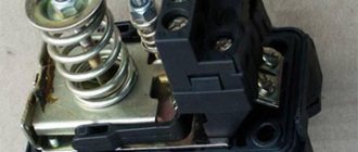
Design and diagram of a pressure switch for the compressor
All compressor pressure switches are divided into two types:
- Switching off the compressor electric motor when the air pressure in the network exceeds permissible limits (such designs are called normally open);
- Turning on the compressor electric motor when the pressure in the network decreases below permissible limits (such designs are called normally closed).
The actuator element of the pressure switch for the compressor is springs, the compression force of which is changed by a special screw. In the factory settings, the compression force of the springs is usually set to a pressure in the pneumatic network from 4 to 6 atm, as reported in the user manual. Since the rigidity and flexibility of spring elements depend on the ambient temperature, all designs of industrial pressure switches are designed for stable operation in the temperature range from -5 to +80ºС.
Selection of compressors with pressure switch
The design of the pressure switch includes two mandatory subassemblies - an unloading valve and a mechanical switch. The unloading valve is connected to the air supply line between the receiver and the compressor. It controls the operation of the electric motor. If the compressor drive is turned off, the unloading valve located on the receiver discharges excess compressed air (up to 2 atm) into the atmosphere, thereby unloading the moving parts of the compressor from the excess force that they will have to develop when the compressor is turned on again. This prevents critical overload of the engine in terms of permissible torque. When the unloaded engine starts, the valve closes and does not create unnecessary load on the drive.
A mechanical switch performs the stand by function, preventing accidental starting of the engine. After pressing the button, the drive turns on and the compressor operates in automatic mode. If the button is turned off, the compressor engine will not start even if the pressure in the pressure pneumatic network is lower than required.
In order to increase work safety, industrial designs of compressor pressure switches are also equipped with a safety valve. It is useful, for example, in case of sudden engine stop, piston failure or other emergency situation.
Optionally, a thermal relay can be installed in the pressure switch housing, with the help of which the current strength in the primary circuit is monitored. If for some reason this parameter increases, then, in order to avoid overheating and subsequent breakdown of the windings, the thermal relay will turn off the electric motor.
- How to connect a motor from a refrigerator without a video relay?
Using a magnetic starter
The good thing about using a 380 electric motor connection diagram is that it can be started remotely. The advantage of a starter over a switch (or other device) is that the starter can be placed in a cabinet, and the controls can be placed in the work area; the voltage and currents are minimal, therefore, the wires are suitable for a smaller cross-section.
In addition, connection using a starter ensures safety in the event that the voltage “disappears,” since this opens the power contacts, and when the voltage appears again, the starter will not supply it to the equipment without pressing the start button.
Connection diagram for a 380V electric asynchronous motor starter:
At contacts 1,2,3 and start button 1 (open), voltage is present at the initial moment. Then it is supplied through the closed contacts of this button (when you press “Start”) to the contacts of the coil starter K2, closing it. The coil creates a magnetic field, the core is attracted, the contacts of the starter close, driving the motor.
At the same time, the NO contact closes, from which the phase is supplied to the coil through the “Stop” button. It turns out that when the “Start” button is released, the coil circuit remains closed, as do the power contacts.
By pressing “Stop”, the circuit is broken, returning the power contacts to open. The voltage disappears from the conductors and NO supplying the engine.
Video: Connecting an asynchronous motor. Determination of engine type.
If you have a three-phase electric motor, you know it doesn't come cheap. Therefore, if you need to use a single-phase motor, the thought of buying new equipment will only come to you when you do not know how to make an electric motor at home. We will tell you how to convert an electric motor from 380 to 220 Volts with your own hands.
How to connect and configure a pressure switch?
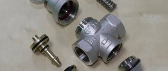
In the general circuit diagram of a compressor installation, the pressure switch is located between the unloader valve and the secondary engine control circuit. Typically the pressure switch is equipped with four threaded heads. One of them is intended for connecting the device to the receiver, and the second is for connecting a control pressure gauge. One of the remaining connectors can be used to install a safety valve, and the remaining one can be fitted with a regular ¼-inch threaded plug. The presence of a free connector allows you to install the control pressure gauge in a place convenient for the user.
The pressure switch is connected in the following sequence:
- Connect the device to the unloading valve of the receiver.
- Install a control pressure gauge (if it is not necessary, then the threaded inlet is also plugged).
- Connect the terminals of the electric motor control circuit to the contacts (taking into account the selected connection diagram - to normally open or normally closed contacts). When the voltage in the network fluctuates, the connection is made not directly, but through a surge protector. This is also required when the power for which the contacts are designed exceeds the motor load current.
- If necessary, use the adjusting screws to adjust the relay to the required compressed air pressure values.
When connecting, you need to check whether the network voltage corresponds to the factory settings of the compressor pressure switch.
For example, in a three-phase network with a voltage of 380 V, the relay must have a three-contact group (two phases + zero), and for a voltage of 220 V - a two-contact group. The adjustment is made when the receiver is at least two-thirds full. To perform this operation, the relay is disconnected from the power supply, and, by removing the top cover, the compression of the two springs is changed. The adjusting screw, on which the axis of the larger diameter spring is mounted, is responsible for the upper limit of the working pressure. On the board next to it, the generally accepted pressure symbol (P - pressure) is usually indicated, and the direction of rotation of the screw by which this pressure is reduced or increased is also indicated. The second, smaller adjustment screw is responsible for setting the required pressure range (difference). It is marked with the symbol ΔР, and is also equipped with an indicator of the direction of rotation.
To reduce setup time, in some designs the adjusting screw for changing the upper pressure limit is moved outside the pressure switch housing. The result is monitored using the pressure gauge readings.
Let's first consider how a three-phase motor is connected to a 380V network.
Three-phase motors come with either three terminals - for connection to a star only - or with six connections, with the ability to select a circuit - star or delta. The classic scheme can be seen in the figure. Here in the picture on the left there is a star connection. The photo on the right shows how it looks on a real engine frame.
It can be seen that for this it is necessary to install special jumpers on the required pins. These jumpers come with the motor. In the case where there are only 3 terminals, the star connection is already made inside the motor housing. In this case, it is simply impossible to change the winding connection diagram.
Some say that they did this to prevent workers from stealing units from home for their own needs. Be that as it may, such engine options can be successfully used for garage purposes, but their power will be noticeably lower than those connected by a triangle.
DIY pressure switch
With known skills, as well as the presence of a working thermostat from a decommissioned refrigerator, a pressure switch can be made independently. True, it will not have any special practical capabilities, since the ability to maintain upper pressure is limited by the strength of the rubber bellows.
Thermal relays of the KTS 011 type are most convenient for conversion into a compressor pressure switch, since they have a strictly reverse sequence of operation: when the temperature in the refrigeration chamber increases, the relay turns on, and when it decreases, it turns off.
The essence and sequence of work is as follows. After opening the cover, the location of the desired group of contacts is established, for which it is enough to ring the circuit. First, the connection between the thermal relay and the compressor is finalized. To do this, the outlet pipe, together with the control pressure gauge, is connected to the unloading valve, and the contact groups are connected to the terminals of the electric motor circuit. An adjusting screw will be found under the thermostat cover. When the compressor is turned on (the receiver should be filled to no more than 10...15% of its nominal volume), the screw is rotated sequentially, monitoring the result using the pressure gauge. To set the lower position (which determines the minimum air pressure), you will have to gradually move the face button rod. To do this, the cover is installed in place, and the adjustment is actually made blindly, since there is nowhere to connect the second pressure gauge.
- Step-down transformers 380/220
For safety reasons, the pressure adjustment range using such a thermal relay cannot be more than 1...6 atm, however, using devices with a more durable bellows, you can increase the upper range to 8...10 atm, which in most cases is quite sufficient.
After checking the functionality of the relay, the capillary tube is cut off and the refrigerant contained there is released. The end of the tube is soldered into the unloading valve.
Next, work is carried out to connect a homemade pressure switch to the compressor control circuit: using a nut, the relay is attached to the control board, a thread is made on the rod, and a lock nut is screwed on, by rotating which you can adjust the limits of air pressure change.
Considering that the contact group of any thermal relay from a refrigerator is designed for fairly high currents, in this way it is possible to switch circuits of significant power, including secondary compressor motor control circuits.
How to select capacitors for a three-phase motor using it in a 220V network.
The first thing you need to know is that the capacitors must be non-polar, that is, not electrolytic. It is best to use containers of the brand ― MBGO. They were successfully used in the USSR and in our time. They perfectly withstand voltage, current surges and the damaging effects of the environment.
They also have mounting eyes that help you easily place them at any point on the device’s body. Unfortunately, getting them now is problematic, but there are many other modern capacitors that are no worse than the first ones. The main thing is that, as mentioned above, their operating voltage is not less than 400V.
Calculation of capacitors. Working capacitor capacity.
In order not to resort to long formulas and torture your brain, there is a simple way to calculate a capacitor for a 380V motor. For every 100 W (0.1 kW) 7 µF is taken. For example, if the motor is 1 kW, then we calculate it like this: 7 * 10 = 70 µF. It is extremely difficult to find such a capacity in one jar, and it is also expensive. Therefore, most often the containers are connected in parallel, gaining the required capacity.
Starting capacitor capacity.
This value is taken at the rate of 2-3 times greater than the capacity of the working capacitor. It should be taken into account that this capacity is taken in total with the working capacity, that is, for a 1 kW motor, the working capacity is equal to 70 μF, multiply it by 2 or 3, and get the required value. This is 70-140 µF of additional capacitance - starting. At the moment of switching on, it is connected to the working one and the total is 140-210 µF.
Features of the selection of capacitors.
Capacitors, both working and starting, can be selected using the method from smallest to largest. Having thus selected the average capacity, you can gradually add and monitor the operating mode of the engine so that it does not overheat and has enough power on the shaft. Also, the starting capacitor is selected by adding until it starts smoothly without delays.
In addition to the above type of capacitor - MBGO, you can use the type - MBGCh, MBGP, KGB and the like.
Design and diagram of a pressure switch for the compressor
All compressor pressure switches are divided into two types:
- Switching off the compressor electric motor when the air pressure in the network exceeds permissible limits (such designs are called normally open);
- Turning on the compressor electric motor when the pressure in the network decreases below permissible limits (such designs are called normally closed).
The actuator element of the pressure switch for the compressor is springs, the compression force of which is changed by a special screw. In the factory settings, the compression force of the springs is usually set to a pressure in the pneumatic network from 4 to 6 atm, as reported in the user manual. Since the rigidity and flexibility of spring elements depend on the ambient temperature, all designs of industrial pressure switches are designed for stable operation in the temperature range from -5 to +80ºС.
The design of the pressure switch includes two mandatory subassemblies - an unloading valve and a mechanical switch. The unloading valve is connected to the air supply line between the receiver and the compressor. It controls the operation of the electric motor. If the compressor drive is turned off, the unloading valve located on the receiver discharges excess compressed air (up to 2 atm) into the atmosphere, thereby unloading the moving parts of the compressor from the excess force that they will have to develop when the compressor is turned on again. This prevents critical overload of the engine in terms of permissible torque. When the unloaded engine starts, the valve closes and does not create unnecessary load on the drive.
What can be redone
Low-power 380 Volt electric motors are suitable for conversion: up to 3 kW. Theoretically, powerful motors are also reconnected. But this will additionally entail the installation of a separate circuit breaker in the electrical panel and special wiring. And this work becomes meaningless if it suddenly turns out that the input cable cannot carry such a load.
Read also: Btb10 800bw how to check with a tester
Even if your network carries high loads, and you managed to convert a 3 kW motor from 380 to 220 Volts, you will be upset the first time you put it into operation. The launch will be difficult. You will decide that the work was in vain. Therefore, if you redo it, then it will be low-power models.
How to connect and configure a pressure switch?
In the general circuit diagram of a compressor installation, the pressure switch is located between the unloader valve and the secondary engine control circuit. Typically the pressure switch is equipped with four threaded heads. One of them is intended for connecting the device to the receiver, and the second is for connecting a control pressure gauge. One of the remaining connectors can be used to install a safety valve, and the remaining one can be fitted with a regular ¼-inch threaded plug. The presence of a free connector allows you to install the control pressure gauge in a place convenient for the user.
The pressure switch is connected in the following sequence:
- Connect the device to the unloading valve of the receiver.
- Install a control pressure gauge (if it is not necessary, then the threaded inlet is also plugged).
- Connect the terminals of the electric motor control circuit to the contacts (taking into account the selected connection diagram - to normally open or normally closed contacts). When the voltage in the network fluctuates, the connection is made not directly, but through a surge protector. This is also required when the power for which the contacts are designed exceeds the motor load current.
- If necessary, use the adjusting screws to adjust the relay to the required compressed air pressure values.
When connecting, you need to check whether the network voltage corresponds to the factory settings of the compressor pressure switch.
For example, in a three-phase network with a voltage of 380 V, the relay must have a three-contact group (two phases + zero), and for a voltage of 220 V - a two-contact group. The adjustment is made when the receiver is at least two-thirds full. To perform this operation, the relay is disconnected from the power supply, and, by removing the top cover, the compression of the two springs is changed. The adjusting screw, on which the axis of the larger diameter spring is mounted, is responsible for the upper limit of the working pressure. On the board next to it, the generally accepted pressure symbol (P - pressure) is usually indicated, and the direction of rotation of the screw by which this pressure is reduced or increased is also indicated. The second, smaller adjustment screw is responsible for setting the required pressure range (difference). It is marked with the symbol ΔР, and is also equipped with an indicator of the direction of rotation.
Connection diagram for a 3-phase motor in a 220V network connected by a star.
As you can see, the 220V voltage is distributed over two series-connected windings, where each is designed for such a voltage. Therefore, the power is lost almost twice, but such an engine can be used in many low-power devices.
The maximum power of a 380V motor in a 220V network can only be achieved using a delta connection. In addition to minimal power losses, the engine speed also remains unchanged. Here, each winding is used for its own operating voltage, hence the power. The connection diagram for such an electric motor is shown in Figure 1.
Fig. 2 shows a terminal with a 6-pin terminal for delta connection. The three resulting outputs are supplied with: phase, zero and one terminal of the capacitor. The direction of rotation of the electric motor depends on where the second terminal of the capacitor is connected - phase or zero.
In the photo: an electric motor with only working capacitors and no capacitors for starting.
DIY pressure switch
With known skills, as well as the presence of a working thermostat from a decommissioned refrigerator, a pressure switch can be made independently. True, it will not have any special practical capabilities, since the ability to maintain upper pressure is limited by the strength of the rubber bellows.
Thermal relays of the KTS 011 type are most convenient for conversion into a compressor pressure switch, since they have a strictly reverse sequence of operation: when the temperature in the refrigeration chamber increases, the relay turns on, and when it decreases, it turns off.
The essence and sequence of work is as follows. After opening the cover, the location of the desired group of contacts is established, for which it is enough to ring the circuit. First, the connection between the thermal relay and the compressor is finalized. To do this, the outlet pipe, together with the control pressure gauge, is connected to the unloading valve, and the contact groups are connected to the terminals of the electric motor circuit. An adjusting screw will be found under the thermostat cover. When the compressor is turned on (the receiver should be filled to no more than 10...15% of its nominal volume), the screw is rotated sequentially, monitoring the result using the pressure gauge. To set the lower position (which determines the minimum air pressure), you will have to gradually move the face button rod. To do this, the cover is installed in place, and the adjustment is actually made blindly, since there is nowhere to connect the second pressure gauge.
For safety reasons, the pressure adjustment range using such a thermal relay cannot be more than 1...6 atm, however, using devices with a more durable bellows, you can increase the upper range to 8...10 atm, which in most cases is quite sufficient.
After checking the functionality of the relay, the capillary tube is cut off and the refrigerant contained there is released. The end of the tube is soldered into the unloading valve.
Next, work is carried out to connect a homemade pressure switch to the compressor control circuit: using a nut, the relay is attached to the control board, a thread is made on the rod, and a lock nut is screwed on, by rotating which you can adjust the limits of air pressure change.
Considering that the contact group of any thermal relay from a refrigerator is designed for fairly high currents, in this way it is possible to switch circuits of significant power, including secondary compressor motor control circuits.
sticking out of the engine were two wires to the network and two to the button
Let's summarize.
Sometimes it becomes necessary to change the direction of rotation of the electric motor. This option is also available for 380V motors used in a single-phase network. To do this, you need to make sure that the end of the capacitor connected to a separate winding remains unbroken, and the other can be transferred from one winding, where the “zero” is connected, to the other, where the “phase” is connected.
This operation can be performed by a two-position switch, the central contact of which is connected to the output from the capacitor, and to the two outer terminals from “phase” and “zero”.
More details can be seen in the figure.
There are three-phase electric motors for 220V. Each winding of them is designed for 127V and when connected to a single-phase network in a delta circuit, the motor will simply burn out. To prevent this from happening, such a motor should be connected to a single-phase network only according to the “star” circuit.
Safety precautions
Although a drill press is easy to connect and use, working with it can be dangerous without proper safety precautions. Among them it is worth highlighting the following:
- Perform any repair or cleaning work only with the engine power off;
- use protective clothing and glasses to protect yourself from flying chips, dust, drops of cutting fluid, and parts of the drill that break;
- hide long hair under a hat, avoid working with gloves - if they get wrapped around rotating elements, they can lead to serious injuries;
- Before starting work, carefully check all moving parts of the machine for defects and damage. If they are detected, it is prohibited to use the device.
To find out more about how to connect a drilling machine, contact Metaltool and they will answer your questions in detail.
Source