To ensure that the water pressure in the autonomous water supply (heating) system remains stable, a special device is installed in it - a hydraulic accumulator. At the same time, an integral part of this unit is a very small device - a pressure switch.
If the latter is not configured correctly, the hydraulic accumulator will constantly turn on and off unnecessarily. As a result, we will get excessive energy consumption and rapid wear of pumping equipment.
Agree, by installing a hydraulic accumulator at home, we want to increase the efficiency of the water supply system and the stability of its operation. However, if the adjustment of the pressure switch is carried out with errors, then the task will not be achieved. It is extremely important to set up this small device accurately and according to the rules. Moreover, it needs to be adjusted both during initial installation and later, during continuous operation.
Place of the device in the water supply system
The hydraulic accumulator (HA) consists of a container, a bleed valve, a flange, a 5-pin fitting (tee) with couplings for connection, as well as a pressure switch (control unit), which sets the rhythm of all work.
Functions:
- main control element
- ensures work without overloads
- controls optimal filling of the tank with water
- extends the service life of the membrane and all equipment in general
A pressure gauge that shows the pressure in the tank is included in the kit or can be purchased separately.
The pump pumps water out of the well and directs it through pipes. Next, it enters the GA, and from it into the home pipeline. The purpose of the membrane tank is to maintain stable pressure, as well as the operating cycle of the pump. There is a certain maximum activation for it - about 30 per hour. If exceeded, the mechanism experiences stress and may fail after a short time. The water pressure switch must be adjusted so that the devices operate as expected, without exceeding the critical load.
Setting up a storage tank means creating the required number of atmospheres in it and correctly setting the pump response thresholds
How to choose a hydraulic accumulator for water supply systems of a private house
Before purchasing, you should consider all the parameters of the hydraulic tank
Particular attention should be paid to:
- tank volume;
- type of location;
- type of energy storage;
- nominal pressure;
- cost of the selected model.
The certificate of conformity for a hydraulic tank looks like this.
When purchasing, you should ask your sales consultant about the availability and cost of replacement membranes or cylinders for the selected model and how accessible they are in principle. It would be useful to check the accompanying documentation and certificate of conformity, as well as clarify the warranty period for the device.
Important information! If you plan to install it yourself, you need to find out whether this is a reason to void the warranty. Some manufacturers oblige buyers to hire professional installers - this is prescribed as one of the clauses of the warranty service agreement.
It is quite difficult to understand the range of such products. Today, products from various companies are presented on store shelves. In order to help the reader, we will consider the most famous and popular among the population.
Diagram of a water supply device from a well with the inclusion of a hydraulic accumulator
Design and principle of operation
The device looks like a box of various shapes with controls under the lid. It is attached to one of the outlets of the fitting (tee) of the container. The mechanism is equipped with small springs that are adjusted by turning the nuts.
Operating principle in order:
- The springs are connected to a membrane that responds to pressure surges. An increase in indicators compresses the spiral, a decrease leads to stretching.
- The contact group reacts to these actions by closing or opening the contacts, thereby transmitting a signal to the pump. The connection diagram necessarily takes into account the connections of its electrical cable to the device.
- The storage space fills up and the pressure increases. The spring transmits the pressure force, the device operates according to the set values and turns off the pump, sending it a command to do so.
- The liquid is consumed - the pressure weakens. This is fixed, the engine turns on.
The assembly consists of the following parts: a housing (plastic or metal), a membrane with a cover, a brass piston, threaded pins, metal plates, cable sleeves, terminal blocks, a hinged platform, sensitive springs, and a contact assembly.
The operating algorithm of the control device is as simple as possible. The mechanism responds to changes in the number of atmospheres inside the drive. The moving platform is raised or lowered by springs depending on the pressure on the piston, which in turn interacts with contacts that signal the pump to start or stop pumping.
Determination of tank parameters
In most cases of inclusions, hydraulic tanks for water supply are installed according to the principle: the larger the volume, the better. But too large a volume is not always justified: the hydraulic tank will take up a lot of useful space, the water will stagnate in it, and if power outages happen very rarely, there is simply no need for it. A hydraulic tank that is too small is also ineffective - if a powerful pump is used, it will turn on and off frequently and quickly fail. If a situation arises when installation space is limited or financial resources do not allow you to purchase a large-capacity storage tank, you can calculate its minimum volume using the formula below.
Rice. 6 How to correctly calculate the volume of a hydraulic tank in a water supply system
Another calculation method is to calculate the required volume of the hydraulic tank based on the power of the electric pump used.
Recently, modern high-tech electric pumps with soft start and stop, frequency control of the speed of rotation of the impellers depending on water consumption have appeared on the market. In this case, there is no need for a large-volume hydraulic tank - soft start-up and adjustment do not cause water hammer, as in systems with conventional electric pumps. Automatic control units of high-tech devices with frequency control have a built-in hydraulic tank of a very small volume, designed for its pump group.
Fig. 7 Table of calculated values of pressure and volume of the hydraulic tank depending on the operating modes of the water supply line
Installation
Often the HA kit is sold disassembled, and the control unit must be installed yourself.
Connecting the pressure switch to the hydraulic accumulator looks like this in stages:
- The station is disconnected from the network. If water has already been pumped into the storage tank, it is drained.
- The device is fixed permanently. It is screwed onto the 5-pin fitting of the unit or onto the outlet pipe and must be firmly fixed.
- The wiring diagram is normal: there are contacts for the network, pump, and grounding. The cables are passed through holes on the housing and connected to contact blocks with terminals.
Electrical connection to the pump
Preventing problems
The main problems include:
- reducing the pressure inside the accumulator;
- water not entering the hydraulic tank.
| Problem | Cause of occurrence |
| Pressure drop | The appearance of leaks at the flange-nipple interface. The occurrence of leakage at the junction of the flange and the pear-shaped membrane. |
| No water ingress | Clogged filters. A sharp decrease in power supply or frequent power outages. Air entering the hydraulic tank. |
To prevent problems, regular preventive measures are required, namely:
- examination of the inside of the tank every 6 months;
- annual check of membrane tightness;
- monthly inspection of the pump for external defects;
- Check the pressure switch every six months.
If the use of the hydraulic accumulator is stopped for the winter, then it is necessary to drain the water from it, and before use, check all elements for external and internal damage.
Settings
Before adjusting the relay, you need to take into account that its values are inextricably linked with the pressure inside the membrane tank. First you need to create the required amount of pressure inside it, and then move on to working with the control in question.
The adjustment is carried out in 3 stages:
- pressure inside HA
- pump start level
- shutdown mark
For optimal operation, it is necessary to adjust the parameters several times experimentally, taking into account the water flow, the height of the pipes and the pressure in them.
Indicators inside the accumulator
It is advisable that the pressure adjustment in the accumulator take into account the following examples and rules:
- for a one-story house, 1 bar is enough, and if the tank is installed in the basement, then add 1 more
- the value must be greater than at the highest point of water intake
- how many atmospheres should be inside the container is determined by the following formula: add 6 to the height of the pipes to the highest point of water intake and divide the result by 10
- if there are many consumption points or the branching of the pipeline is significant, then a little more is added to the resulting figure. How much to add is determined empirically. There is the following rule for this. If the value is too low, then water will not be delivered to the devices. If it is too high, the HA will be constantly empty, the pressure will be too strong, and there will also be a risk of membrane rupture.
In order to increase the pressure in the accumulator, air is pumped up with an ordinary bicycle pump (there is a special spool on the body); to lower it, it is vented. The pneumatic valve for this purpose is located under the decorative trim. The procedure must be done in the absence of water pressure, which requires simply closing the taps.
The value of the indicators is determined by a pressure gauge connected to the spool. The correction is made after the pump has turned off. The pressure difference is created by opening the tap at the nearest point.
Manufacturers standardly set the pressure in the tank to 1.5 - 2.5 bar. Its increase reduces the usable space inside the container and increases the pressure in the system - this must be taken into account when calculating.
Basics of adjusting thresholds
There are two springs with nuts: the larger one is responsible for the values for turning off the pump, the smaller one is for turning it on. The bolts are loosened or tightened, thereby making adjustments.
Setting up the accumulator pressure switch will be of high quality if you follow these rules:
- the average recommended difference between the values for turning the pump on and off is 1 - 1.5 atm
- the pressure inside the HA must be lower than the set value to turn on the pump by 10%. Example: if the activation mark is set to 2.5 bar, and the switch off mark is set to 3.5 bar, then there should be 2.3 bar inside the container
- the hydraulic accumulator and control unit have their own load limits - when purchasing, you need to check whether they coincide with the calculations for the system (pipe height, number of intake points, flow rate)
The mechanism in question controls the maximum and minimum pressure in the tank. It maintains the difference in its values when the station is activated and switched off. The limit of its settings depends on the power and hourly flow rate of the pump.
Factory parameters are indicated in the product data sheet. Usually they are like this:
- limit limits – 1 – 5 atm
- pump operating range – 2.5 atm
- starting point – 1.5 atm
- maximum switch-off level – 5 atm
Preparation and example of setting the required values
Preparation:
- tank is connected
- the control unit is adjusted under pressure, the system is not disconnected from the power supply
- inside the unit the pressure should be 10 - 13% lower than that of the pumping station. That is, approximately 0.6 - 0.9 atm than the mark at which the engine turns on
- all taps are closed
- the set level is checked with a pressure gauge within an hour to make sure there are no leaks
- remove the block housing cover to have access to the nuts and observe the springs
Setting with an example of setting marks of 3.2 atm to turn off and 1.9 atm to turn on (two-story house):
- Start the pump to determine the pressure in the system. It should fill the storage part of the device and increase the pressure.
- They determine at what pressure gauge reading the shutdown will occur (usually no more than 2 atm.) When exceeded, a small spring comes into action, which is clearly visible.
- The motor is stopped above 3.2 - 3.3 atm, this figure is reduced by rotating the nut on the small spring a quarter turn, since it is very sensitive, until the motor turns on.
- They check with a pressure gauge: 3 - 3.2 atm will be enough.
- Turn on the tap to relieve the pressure and so that the HA is freed from the liquid and record the pump activation mark with a pressure gauge, usually 2.5 atm - the lower pressure indicator has been reached.
- To reduce the lower threshold, rotate the large spring bolt counterclockwise. Next, start the pump until the pressure rises to the required level, after which you need to check the pressure with a pressure gauge. An acceptable value is 1.8 - 1.9 and the nut is rotated clockwise.
- Once again, adjust the small spring a little, clarifying the already set thresholds.
The adjustment bolts are very sensitive - turning just 3/4 of a turn can add 1 atm. The pressure of the switched-on pump should be 0.1 - 0.3 atm higher than in an empty storage tank, which will prevent damage to the “bulb” inside it.
The setup process in brief
For a better understanding of how to set up a pressure switch, we will outline the process more clearly:
- pump activation mark (minimum pressure): rotating the large spring bolt clockwise increases the starting mark, counterclockwise decreases it;
- value for shutdown: move the small spring, when tightening - the pressure difference increases, when unscrewing - the actuation mark decreases;
- the result is checked by opening the tap and draining the water, recording the moment the pump is turned on;
- The internal pressure force is adjusted by deflating or pumping air and checking this with a pressure gauge.
Increasing the factory switching parameters (above 1.5 atm) creates a risk of critical load on the hydraulic tank membrane. The operating range of the pump is adjusted taking into account the maximum possible load for the water fittings. The sealing rings of household taps can withstand a maximum of 6 atm.
Video description
What the pressure should be, see the video:
Optimizing underpressure
The problem of excess pressure also occurs, but quite rarely. Most often it is not enough, and this issue is solved in several ways. Here are the two most popular.
With booster pump
A booster pump is included in the system. That is, this pump is not present to supply water, but to forcibly increase its pressure. This solution can be considered optimal when there is water in the source, but due to its distance from the distribution points, it loses pressure along the way.
Scheme with booster pumps Source ppt-online.org
It is ideal when such a pump is controlled automatically, which itself starts and stops its operation when necessary. This option is suitable for both private houses and apartments, but in the latter case there is a risk of leaving neighbors without water.
Using a storage tank
If there is not enough water in the well (the flow rate of the source is reduced), installing a booster pump will not only not solve the problem, but will also aggravate it. In this case, a sufficiently large storage tank must be installed in front of this pump, and in the absence of water intake, water will be pumped into it.
In this case, the owner himself will decide what pressure is in the accumulator, because this is not important. If such a tank is equipped with a float sensor, it will itself give the pump a command to turn on when the water in the tank is used up to a certain limit.
System with large storage capacity Source seid-nn.ru
If you place the container in the attic, it will also be filled by means of a pump, but it will flow to the flow points by gravity. True, the pressure will not be strong enough, and most likely, you will have to install another pump that will supply water from the tank. By using the second pump, you can place the barrel anywhere – even in the basement.
Maintenance, problems, operation
Preventative actions and repairs:
- mechanical sensitive parts need to be checked and adjusted
- It is advisable to clean the contacts
- If it doesn’t work, don’t rush to disassemble the mechanism - first try lightly tapping the body with a not too heavy object
- Rocker joints are lubricated with grease once a year
- do not tighten the adjustment nuts completely - the mechanism will not work
If the device does not hold pressure, does not work correctly, or does not work at all, refrain from hasty conclusions and do not throw it away. Dust, debris, sand in the membrane space prevent it from reacting normally. Steps to fix the problem are:
- Unscrew the 4 bolts on the bottom, remove the cover with the inlet pipe and the cover.
- Carefully rinse the membrane and the cavities around it.
- Install all elements in reverse order.
- Set the thresholds again and carry out a test run.
Experts recommend that before setting up the relay correctly, do not exceed the upper threshold by more than 80% of the maximum permissible values for a specific model, which are indicated in the instructions (standard about 5 - 5.5 atm.).
For high-quality operation, there should be no air in the pipeline. Periodically (once every 3-6 months) you need to check the set response thresholds, pressure indicators in the HA, and bleed or pump in air. Before you start setting up, you need to find out whether the pressure switch for the hydraulic accumulator and the unit itself can withstand the required loads, and whether its technical capabilities meet them.
How to check the pressure in the accumulator
The tank must be empty during measurements.
To do this, turn off the pumping station, open the water tap and wait until the water supply stops. To measure pressure you need:
- unscrew the cap that closes the fitting with the spool located on the tank body;
- connect the pressure gauge to the spool (you can use an electronic or automobile pressure gauge), take the reading and compare it with the calculated value;
- if the pressure level decreases, pump up the compressor to the optimal value;
- To reduce pressure, bleed air.
If adjustment is carried out before the hydraulic tank is included in the system, it must be left for a day. After this time, after a control measurement, the device is installed.
Horizontal or vertical
Depending on the installation method, hydraulic accumulators can be vertical or horizontal. Which hydraulic accumulator is preferable? It is necessary to find out how the device removes the air collected inside the membrane (“pear”). The fact is that in any water supply system there is air dissolved in the water. Over time, it is released from the water and, accumulating, forms air plugs at different points in the system. To remove them, large-volume hydraulic accumulators (? 100 liters) are provided with a fitting with a valve through which the air accumulated in the system can be released from time to time. In vertical type hydraulic accumulators (from 100 l), all air is collected in the upper part of the unit and is easily removed using such a valve. In horizontal hydraulic accumulators, air is removed using an additional section of piping consisting of a ball valve, air outlet nipple and drain. Small volume hydraulic accumulators do not have such a valve. Removal of collected air is possible only when the tank is completely emptied. Typically, horizontal hydraulic accumulators are chosen for installing external pumps on them, and vertical ones are chosen for small spaces and when working with submersible pumps. Return to content
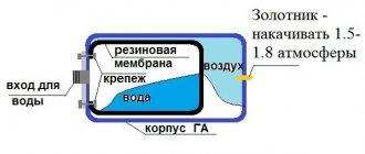
What is a hydraulic accumulator
A hydraulic tank (or hydraulic accumulator) is a water container with a rubber elastic membrane (resembling a pear) located inside the container and having a sealed connection to the metal body of the tank. This connection is made using a flange with a threaded connection to connect the device to the water supply. The cavity between the membrane and the metal body of the hydraulic tank is filled with compressed air, usually the pressure is 1.5-2 bar. Hydraulic accumulators are used to maintain constant pressure and create a water reserve in domestic or industrial conditions. It is this unit that provides the required pressure in the system when the pump is turned off.
Fig.1.
Hydraulic accumulator structure 1 – metal body; 2 – rubber membrane; 3 – flange with valve (passes air); 4 – nipple for pumping air into free space; 5 – cavity for compressed air; 6 – supports; 7 – platform for the pump. More details about the design of the hydraulic tank in the video: Return to content
The pumping station does not pump water: reasons, how to fix it
The pumping station does not pump Why does the pumping station not pump water? This is a question that many owners of equipment ask themselves, which is often an integral part of the water supply system for a country house from a well or well. One of the reasons for unit malfunctions is that the pumping station pumps water with air. How to get rid of this phenomenon is suggested in the article.
If the motor is running, but water does not flow, then the reasons are as follows: