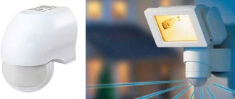
A motion sensor is an electronic infrared device that detects the movement of living things and turns on power for lights and other electronic devices. Most often, such sensors are installed for lighting, but can be used for other purposes, for example, turning on a sound alarm.
The motion sensor operates on the principle of an electrical switch. a regular electric switch on and off mechanically by hand, and the motion sensor turns on automatically, reacting to movement, and turns off automatically when the movement stops.
The motion sensor is used in conjunction with lighting, as well as for turning on a sound alarm, opening doors, such as supermarket doors, etc.
Types of motion sensors
By location:
- Perimetric, used outdoors.
- Peripheral.
- Internal.
Based on the operating principle:
- Ultrasonic – a reaction to high-frequency sound waves.
- Microwaves – respond to high frequency radio waves.
- Infrared - uses heat radiation.
- Active - equipped with a receiver and transmitter.
- Passive - without a transmitter.
By type of operation:
- Thermal - triggered when the temperature changes.
- Sound - act on air vibrations.
- Oscillatory - triggered by a magnetic field.
By design:
- 1-position – equipped with a transmitter and receiver in one housing.
- 2-position – receiver and transmitter in different housings.
- Multi-position - equipped with several blocks.
By type of installation:
- Multifunctional.
- Indoor.
- External.
- Overhead (wall-mounted).
- Ceiling (for suspended ceiling).
- Mortise (for offices).
Operating principle
The operating principle is not difficult to understand and is simple. The detector detects an object, sends a signal to a relay, which closes the circuit, and the light bulb lights up.
Connecting motion sensors using an example
To better understand how a motion sensor works, let’s conduct an experiment connecting it to a light bulb. For this we need:
- Motion Sensor.
- Electrical plug.
- Indicator screwdriver for phase search.
- Electric cartridge.
- Bulb.
- Screw clamp.
- The wire.
- Cleaning tool.
First, we will connect the light bulb directly to the socket, and then we will connect the motion sensor to the open circuit in order to understand the operation of the sensor.
We take the electrical wire and connect the ends to the plug. To strip the wire, we use a special stripping tool that is convenient to use. We install the cartridge on the opposite side. Screw in the light bulb.
Using an indicator screwdriver, we determine where the phase is in the socket. We insert the plug into the socket and make sure that the light is on. Now you need to install a motion sensor in the wire gap. Turn off the power supply and cut both wires. We clean the ends of the wires.
Now our task is to install the sensor into the gap in the supply wire. You need to connect a zero to the sensor according to the instructions to power it, and pass the phase through the sensor to the light bulb. The phase will enter the brown wire, come out of the red wire and go to the light bulb. We connect according to this diagram. Take the screw clamp and connect it.
There are two rheostats on the sensor itself. One rheostat is responsible for the time of day. It can be used not only for lighting, but also for turning on other devices. On the left knob, the sun is drawn to the left of it, and the moon is drawn to the right. That is, in order to use the sensor during daylight hours, we set the switch to the mode where the sun is indicated. If we use the sensor at night for lighting, then we switch the sensor to dark mode.
For our experience, we will turn on the checks in daylight mode, since we are doing the check in the light. The second sensor is responsible for the shutdown time. We can set it to minimum, and it will turn off after 5 seconds, or set it to maximum, that is, increase the time from the moment the movement stops. Now we plug the plug into the socket, according to the previously established polarity. We move our hand, the sensor turns on the lamp. Now we don’t make any movements, a few seconds pass, the sensor turns off. Motion sensors are connected in a similar way.
Connection diagrams
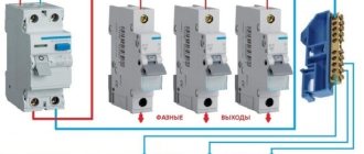
The motion sensors are connected according to the usual circuit of closing and opening the light bulb circuit. If constant lighting is needed, but nothing moves, then a regular switch is included in the circuit parallel to the motion sensor. When the switch is turned on, the light will turn on due to the bypass circuit. When the switch is turned off, lighting control will transfer to the motion sensor.
Connecting motion sensors (several)
Most often, it happens that the shape of the room does not allow one sensor to cover its entire space, for example, around a bend in a corridor. In this case, several sensors are placed and connected in parallel. As a result of the activation of any sensor, the circuit is closed and voltage is supplied to the lighting devices. With this connection method, we must not forget that lighting lamps and sensors must be connected from the same phase. Otherwise a short circuit will occur.
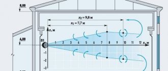
Motion sensors are positioned in such a way that the viewing angle is greatest in the direction of the expected area of object movement. In this case, windows, doors and the interior of the room should not shield or interfere with the operation of the sensor.
Motion sensors have a permissible continuous power value of 500 to 1000 watts. Therefore, they are limited to high-load use.
If it is necessary to turn on many powerful lighting devices, the motion sensors are connected through a magnetic starter.
When purchasing a sensor, see the installation and configuration instructions included with it. Usually the device diagram is indicated on the case. Under the sensor cover there is a connection block, and three contacts are visible by color. The wires are connected using clamps. If the cable is multi-core, then sleeve lugs are used.
Connection features
Electric current is supplied to the sensor through two conductors: brown - phase, and blue - zero. From the sensor, the phase goes to one contact of the light bulb. The other end of the lamp is connected to the zero terminal.
When movement occurs in the control location, the sensor is triggered and closes the relay contacts, which supplies a phase to the lamp.
The terminal block has screw terminals, so the wires are connected with lugs. It is recommended to connect the phase wire according to the diagram specified in the instructions.
Connecting motion sensors comes with some special features:
- After connecting the wiring, close the lid and proceed to connecting the wires in the junction box.
- 9 wires are supplied to the box: 2 - from the lamp, 3 - from the sensor, 2 - from the switch, 2 - zero and phase.
- Wires on the sensor: brown (white) - phase, blue (green) - zero, red - connection to the network.
- The wires are connected as follows: the phase wire (brown) is connected to the brown (white) phase wire of the sensor and the wire from the switch. The zero wire of the power cable is connected to the zero of the sensor and the zero of the lighting lamp.
- There are three wires left - red from the sensor, brown from the lamp and the second wire from the switch. They are connected.
The sensor is connected to the lighting. After power is applied, the sensor shows its reaction to movement, thereby closing the lighting circuit.
Installation instructions
We figured out the connection diagram and operating principle. Now there remains an important and final stage of work - to deal with the installation of the motion sensor.
To independently install and connect motion sensors to the power supply, you must follow a certain procedure:
- Select the connection diagram (one sensor or several, with or without a switch, etc.).
- Determine the most suitable location and direction for mounting the motion sensor. Typically the sensor is mounted on the ceiling or in the corner of the room. When installing outdoors, you need to look at the situation. The main parameter is the viewing angle of the sensor. It is necessary to select the most suitable location for the sensor housing so that there are no dead zones (places that the sensor does not cover with its action). To do this, it is recommended to use lantern supports or a load-bearing wall of the building.
- Turn off the electricity at the switchboard to ensure safety when connecting wires.
- According to the selected circuit option, connect three wires to the contacts of the sensor housing and in the housing of the lighting device. At the same time, do not forget about observing the markings according to the colors of the wires and the designations of the connectors, in order to avoid confusion. If you connect the zero and phase incorrectly, you expose yourself to danger and also damage the electrical wiring, so when connecting you need to work carefully and carefully.
- You need to adjust the regulators on the sensor body and select their optimal settings. There may be several common regulators on the sensor body: Lux - light level for activation, Time - time delay for turning off the light, Sens - sensitivity of the sensor sensor, Mic - noise level for sensor activation. These settings are individual in each case.
Connecting a two-wire motion sensor
Typically, such devices are installed in place of the switch, which requires a standard socket box. In this case, the sensor itself crashes into the phase wire, which is constantly energized. Exactly like a switch. That is, the device that tracks movement will be located between the light bulb and the 220-volt machine.
Let’s immediately make a reservation that such a circuit must be installed separately from the general lighting network. That is why it is necessary to add a distribution box and an automatic machine to the device package. The latter is installed in the distribution board. An electrical circuit of a three-core cable with a cross-section of 3x1.5 mm is drawn from it towards the sensor installation site. But to the sensor installation site you need to stretch a two-core 2x1.5 mm cable.
Sensor mounting height – 1.2-2 m Source stroy-podskazka.ru
The device itself must be installed on the wall at a height of 1.2-2.0 m. Please note that this option differs from those installed at the entrance to the entrance or passage corridors. The latter are suspended up to the ceiling. And they connect differently. And one more point - the installation site should be located so that opening doors cannot block the view. It is important. Manufacturers also do not recommend installation above radiators or other heating elements.
So, three cables should go into the junction box at once:
- from a machine;
- from the lamp;
- from the sensor.
A three-phase cable is output to the lamp.
Now the connection of the motion sensor itself, or rather its diagram. First of all, the neutral conductors from the machine and the lamp are connected to each other. Next is the grounding circuit of the same elements, if present. Now the power veins:
- automatic sensor;
- sensor-lamp.
Connection diagram for a two-wire motion sensor Source dompokrov.ru
The next stage is connecting a motion sensor for lighting. It’s as simple as shelling pears, the main thing is attentiveness. The wire that connects to the light bulb must be connected to the terminal where the light bulb is drawn. Some devices have a “load” sign. The other one to the terminal marked "L". After which the connected product must be installed in the socket box and covered with a decorative strip.
All that remains is to configure the motion sensor. What needs to be done for this. There are three or four checkboxes on the front panel:
- The first of them must be set to automatic mode, that is, with a pointer to the letter “A”.
- The second checkbox adjusts the sensitivity to motion. For example, so that the light does not turn on during the daytime.
- The third checkbox specifies the shutdown time. That is, when the movement stops, the lamp should turn off, for example, after 30 seconds.
Basically, this is all about connection and configuration. What are the advantages of a two-wire motion sensor:
- ease of installation and configuration;
- it is possible to turn on the light manually;
- high versatility of the product.
As for the shortcomings, this is the only one. Two-wire models do not work well with LEDs and energy-saving light bulbs. They sometimes flicker a lot.
Rules for setting up a motion sensor Source pp.userapi.com
How the technology works
Infrared remote detectors using QUAD technology have four pyroelectric detectors. They are located differently. As standard, they are installed next to each other, which allows four detection zones using one Fresnel lens or one mirror. However, a much more commonly used arrangement for pyroelectric devices today is to arrange them in two rows of two detectors.
Thanks to this arrangement, the detection zones are grouped into groups of four beams. Looking at the diagram above, it can be concluded that QUAD detectors have two detectors with dual pyroelectric sensors. In infrared detectors with QUAD technology, the electrical signal from each pair of pyroelectrics is processed separately in an analog-to-digital chip.
Connecting a three-wire motion sensor
The name itself already suggests that this device has three connection terminals. It is represented on the market by a large assortment, with both inexpensive specimens and high prices, which often scare off buyers. All models do not differ from each other in terms of operating principle and connection diagram. It’s just that higher quality parts and elements are used in the production of expensive sensors.
Before purchasing a three-wire motion sensor for lighting, it is recommended to pay attention to such a characteristic as moisture resistance. It is denoted by two Latin letters - “IP”. If the device will be installed indoors or under a canopy, then the IP44 marking is suitable. If you decide to install the motion sensor outdoors, then the best option is IP65. Accordingly, the higher the moisture resistance rating, the more expensive the device itself.
Another characteristic that you need to pay attention to. This is the operating temperature. The majority of sensors are designed to operate at temperatures not lower than -20C. At lower temperatures it begins to “glitch”.
As for the diagram for connecting the motion sensor to the lamp, there are two of them: without a switch and with it. Let's look at each position separately.
Three-wire motion sensors Source pobetony.ru
See also: Popular modular house projects
Connection diagram without switch
As in the previous case, to connect you will need wires and a junction box:
- Three wires are inserted into the latter from the machine: phase, neutral and ground.
- Three wires from the lamp are also inserted here if its body is metal, and two if it is made of non-conducting material.
- And a three-wire cable for the motion sensor.
First of all, three neutral wires from different cables must be connected to each other. The grounding conductor from the machine and the “ground” from the lamp are connected to each other.
But now we need to correctly connect the phase conductors. Here the sequence is:
- first, the phase from the machine is connected to the phase from the motion sensor;
- then the second core, also known as the output wire, from the sensor with the phase circuit of the lamp.
Please note that the motion device has three terminals, two of which are for phase conductors. It turns out, in principle, like a two-wire one. That is, the device itself becomes, as it were, an intermediate link in the phase power system.
It is important to connect the motion sensor correctly here. So, by removing the back cover, which is secured with two screws, you can find the terminal box. Three wires of different colors go inward from it: brown, blue and red. The first is connected to the terminal marked "L". The second with “N” and the third with “A”.
With “N” it’s clear, it’s zero. “L” is the terminal for the incoming phase conductor, that is, coming from the machine. “A” is also a phase terminal, only outgoing. The wire coming from the light bulb is connected to it.
Connection diagram for a three-wire sensor without a switch Source www.syl.ru
Attention! Not all devices have wire colors that match the terminal designations. Therefore, be sure to open the lid and make sure that this is true or not. In any case, the connection must be based on the letter designation of the terminals, and not the color of the wires.
This circuit can be used without installing a junction box. To do this, all connections are made at the terminals of the motion sensor. Both neutral wires are connected to each other and installed on the “N” terminal. The wire coming from the machine as a phase wire is connected to the “L” terminal. Then connect terminal “A” and the phase terminal on the lamp with a wire.
So, the light sensor is connected, all that remains is to make the settings. The first thing to do is to establish at what time of day the device should turn the lighting on and off. To do this, you need to turn one of the flags, near which the sun and moon are drawn. It is clear that the sun means the sensor will work during the day, the moon - at night. The last position is also set if the device is mounted in a dark room, for example, in a corridor.
How to configure a three-wire sensor Source ledeffect.ru
See also: Catalog of companies that specialize in electrical work.
The second checkbox is for setting the shutdown time. Here the range is quite wide: from several seconds to several minutes. The display is made by selecting the required time. That is, they checked the box and checked after what time the lighting turned off. If it’s too fast, then increase the range by moving the flag towards the plus side. And vice versa.
Now, regarding sensitivity. That is, will the motion device react to animals: dogs and cats. Many three-wire models do not have a separate checkbox for setting this characteristic. To do this, manufacturers suggest simply changing the angle of inclination. If you do not want the sensor to react to animals, do not point the window towards the floor. It is enough for it to look at the level of a person’s chest. This will ensure that both adults and children are captured. It is better to look at this in the instructions for use, where the manufacturers clearly indicate how to adjust the sensitivity.
Optimally - installing the device in the corner of the room Source piklvs.ru
There is one more point that concerns sensitivity. This characteristic will be maximum if a person passes by the sensor. That is, the rays of the latter are directed perpendicular to the direction of movement. The minimum indicator is when a person is directed directly at the device. Therefore, before connecting the motion sensor to the light bulb, you need to select the correct installation point. This is optimal in the corner of the room, and not directly “above” or “near” the door.
In general, in many respects three-wire devices are better than two-wire devices. But they also have their drawback - they are often connected without an additionally installed switch. That is, without manually turning on the lighting. And if the sensor fails or starts to work incorrectly, then you will have problems with the light. Therefore, below we will look at how to connect a motion sensor for lighting with installing a switch.
Selection rules
When choosing a flashlight with a motion sensor, you need to be guided by clear guidelines in order to buy the thing you really need. To buy worthwhile products that will serve you faithfully for a long period of time, you should evaluate the available assortment according to several criteria:
- manufacturer. Some brands of flashlights equipped with motion sensors have already proven themselves quite well. Therefore, when choosing, you should give preference to them, so as not to run into low-quality products;
- brightness of the glow;
- power consumed by the device. More powerful models are suitable for the street, but low-power models will be sufficient for the home;
- installation method;
Installation option - the maximum perimeter that the built-in sensor can cover;
- purpose of the device. This refers to the area that the lantern should illuminate (indoor or outdoor, illuminating the porch or garden paths, etc.);
- installation method and how the device can be connected to the electrical network.
Separately, it is worth noting that a flashlight with such a sensor should be purchased in specialized stores, and not in markets. This is due to the fact that in the markets you can buy a fake, which will break after only a few months. At the same time, all products in the store are certified and exactly match the quality declared by the manufacturer.
Video description
The video shows how to connect a motion sensor:
Connection diagram with switch
It should be noted right away that the motion sensor and the switch in the circuit are connected in parallel to each other. Therefore, in addition to the fact that all wires, namely ground and zero, are connected in exactly the same way as in the previous case, the connection of phase conductors is carried out like this:
- the wire from the machine is connected to the incoming core of the sensor;
- the same wire from the machine is connected to the switch;
- the output wire from the motion device is connected to the lamp;
- A wire is laid from it to the switch.
This circuit will allow you to turn on the lighting using a switch, regardless of the time of day, and also regardless of whether the motion sensor is working or is broken.
Connection diagram of a sensor with a switch Source elektromontagy.ru
Infrared detectors type QUAD
It is also worth mentioning infrared detectors of the QUAD type. The task of any wireless motion sensor is to detect only the movement of an intruder, without reacting to side effects. In practice, it turns out that this is not at all so simple, because a person, an animal, a draft in a room, and the setting sun cause very similar pyroelectric phenomena. Therefore, it became an important task to create a device that is capable of distinguishing alarming events from false alarms caused by one of the above-mentioned factors.
One way to reduce the sensitivity of detectors to false alarms was to create a sensor that used two pyroelectric detectors located horizontally side by side. A sensor designed in this way has twice as many detection zones as a sensor with a single pyroelectric device. Elimination of false alarms consists of logical summation of the signal from both detectors. They are connected in such a way that the change in their polarization as a result of detecting radiation is always opposite to the other.
Of course, this solution is not ideal. Thanks to the development of technology, another solution is increasingly being used. If you could use two pyroelectric devices in one Wi-Fi motion sensor, then why not use more. As a result of this thinking, the innovative QUAD technology was developed, which allowed the use of up to four pyroelectric detectors.
Video description
The video shows a diagram of connecting a light bulb through a switch and a motion sensor:
Wiring diagram for a motion sensor instead of a switch
I would like to consider another option on how to connect the sensor. For example, this is the situation - you purchased a sensor, but do not want to carry out a large amount of installation work with chiselling of walls and installation of additional elements. In this case, you can remove the switch and install a motion device in its place. But keep in mind that this scheme does not work with all light bulbs.
So, how to make a connection in this case. Firstly, you will need to purchase two additional elements: a diode and a capacitor. The first one - you can take the VDI 1N4007 brand, the second one - 2.2 microfarads at 400V.
The diode is installed between terminals “A” and “N”. The capacitor must be soldered in parallel to the light bulb being used. In fact, the circuit turns out in such a way that only the phase circuit will pass through the motion device. Namely: enter the “L” terminal and exit from the “N” terminal. In this case, terminal “A” remains free. But one of the diode legs sits on it.
By the way, regarding the question of how to connect a motion sensor to an LED spotlight. This particular circuit works very well with LEDs. It should be taken into account that the total power of the light bulbs connected according to this scheme should not exceed 80 W.
Test run
Connect power to the sensor. I recommend using an incandescent light bulb with a power of 25-60 W as a load to indicate the operation of the sensor. Otherwise, if you focus on the clicking of the relay, you may not hear or understand whether it is on or off. Now we check the relays and connections.
I highly recommend turning on any devices during repairs through the minimum possible circuit breaker. In this case - 1-2 Amperes. This is necessary to avoid troubles.
A better option is to connect through a transformer (with an output voltage of 220V) or a difavtomat, this will significantly reduce the risk of electric shock (we will work with open live parts!).
Another option is through a 60-100W incandescent light bulb, this will save you from a short circuit. But it's not convenient.
I recommend your article on the use of circuit breakers.
We check that the required supply voltage is present on the power board.
I won't tell you how to use measuring instruments or how to check parts. If you have questions, write in the comments.
In addition, I urge you to be careful and remember your safety! During repairs it may get fucked up!
Once again we return to where we started the repair (point 1). There is a high probability that after inspection, soldering, and replacement of visually faulty parts, everything will work.
Video description
The video shows a connection diagram for a motion sensor installed instead of a switch:
Other connection schemes
There are many situations when you need to correctly approach the connection of motion sensors. For example, if you need to install this device in a long corridor with turns. It is clear that connecting a cable to each sensor requires large financial costs and a large amount of work. Therefore, a parallel installation scheme for two motion devices is proposed. That is, one common supply line is laid along the corridor. And motion sensors crash into it parallel to each other.
In this case, a person passing along the corridor first falls into the coverage area of one sensor, which turns on the first light bulb along the way. Then it leaves this zone, ending up in another neighboring one. And so on along the entire length of the corridor. That is, along the path of movement, the light bulbs light up and go out.
Another option is when it is necessary to turn on powerful lighting. After all, a standard device is designed for a maximum load of 1 kW. Or today the sensor is connected to ventilation systems or door opening systems. In this case, it is necessary to add magnetic starters or contactors to the circuit. The load is connected through the starter contacts, but the sensor terminals are connected to the coil through the phase circuit.
Diagram of parallel connection of two motion sensors Source i0.wp.com
Purpose
The task of the device is to automatically switch on or off the load at the moment when movement is detected, taking into account the current level of illumination in the room. During the day or morning, when there is enough light in the room, the sensor will not turn on additional lamps.
A common area of application for sensors is adjusting lighting on streets or in entrances, where light is required only for a short period of time when a person is in the space. In everyday life, motion sensors are used to automatically turn on/off lights in rooms where people stay for a short time (for example, in hallways and corridors).
Installation and connection errors
Now let’s look at situations where the motion sensor suddenly starts working incorrectly. One of the main troubles is false inclusions. This is the situation here. If your device suddenly starts turning on spontaneously, then first of all you need to look for extraneous factors. For example, if the sensor is installed on the street, then there is a high probability that the movement of trees in the wind caused the trigger.
It's easy to check. It is necessary to close the device window with opaque tape. If it continues to “glitch”, then the reason is in it, or rather in its malfunction. If the lighting does not turn on, it means that you just need to configure the device correctly. Or move it to another place.
The next mistake is that the phase and zero have been swapped. In principle, for two-wire devices it makes no difference which wire passes through it. Its task is to open and close the circuit. But in terms of safety, the sensor must crash into the phase wire.
Ceiling sensor cannot be installed on a wall Source dachadecor.com
The third situation is when the light bulb suddenly turns on again after being turned off. This usually happens when incandescent light bulbs are installed in the lamp. After all, they do not immediately extinguish, because the filament must cool down. And this is additional radiation of infrared rays. The latter are picked up by the sensor and triggered by their impact. Therefore, the lamp must be installed so that it does not directly hit the window of the motion device.
The fourth situation is when the ceiling sensor is installed on the wall, or vice versa. That is, when purchasing a device, you should know that manufacturers offer ceiling and wall models with different viewing angles. This means they work differently in terms of coverage of the traffic area. Therefore, ceiling models cannot be mounted on a wall, and vice versa.
Fifth, the instrument window is dirty or has a crack. Not everyone knows that there is more than just transparent glass installed on the sensor window. This is the so-called Frenkel lens. It is she who focuses infrared radiation, transmitting signals further along the chain. Any defect or small speck of dirt makes the motion device operate incorrectly.
And other situations of incorrect operation of the motion sensor: glare from windows, a strong gust of wind, operation of an external air conditioner unit, convection of heating devices, movement of warm air.
Power circuits
We don’t delve into the intricacies of operational amplifiers yet; we continue to explore the most obvious and probable.
In this case, this is checking the operation of the power board relay. This relay turns on, that is, a 24V voltage is supplied to its coil, if the key transistor opens. In this case S9013, npn.
It is better to check with the low-current board completely disconnected. We just turned it off when checking the power supply in step 4.
To check the operation of a transistor, its base must be connected to the emitter, preferably through a resistor. It is there (R21, 20 kOhm), or use your own, about 2 kOhm - 33 kOhm. The transistor in this case will be closed (no current flows through it), and the relay should be turned off.
Next, we check the opening of the transistor and, accordingly, the activation of the relay. To do this, through the same resistor (a resistor is required, the jumper will burn the transistor) we connect the base of the transistor to +24V. The relay should turn on.
If the transistor does not work, it must be checked with an ohmmeter by turning off the power (you can check it before manipulating the resistor). How to check a transistor - is it possible, I won’t write?
The relay may also be faulty.
