- Date: 01/31/2015 Rating: 41
A working drawing of the house support is necessary for high-quality construction work.
To complete the correct drawing of the foundation of a house, you need an engineering education, but everyone should be able to read design drawings.
General documentation for the foundation of a house includes sets of drawings, which are drawn up in accordance with the installation work plan. Each individual document is assigned its own number.
The first sheets of working documentation for the foundation must include data on all working drawings:
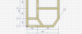
All unmarked foundation beams are BF2.
- a summary sheet of drawings, which includes a list of the main set of design documentation; a sheet of specifications for the materials of the foundation of the house; symbols in accordance with GOST and ESKD; general instructions, reference documents and other data, including sketches, estimate documentation, quality certificates and documents for products.
The basis for creating a set of documents is the assignment for the beginning of the design and the project approved by all authorities. The foundation drawing must include the following marks:
- a mark on compliance with all standards, norms, rules and current legislation; a list of works for which it is necessary to draw up acts for hidden work; a mark on passing control for patent purity.
Principles for creating design documentation for the foundation
Foundation drawings include horizontal and vertical sections of the foundation, which demonstrate the configuration of the main elements of the support: columnar foundations, load-bearing wall structures, columns, equipment, etc. General foundation drawings are drawn on a scale of M1:100, as well as M1:200 and M1:400 . To begin with, the main alignment axes, axes of columnar supports and columns are applied to the drawing.
List of parts for one element.
The foundation outline is drawn with lines with a nominal thickness of 0.5 mm (thin) and 1 mm (main). The general plan must show the design configuration of the main base of the house foundation, preparations and bedding for the base, changes in depth and ledges at different laying depths. It is mandatory to display monolithic and prefabricated structural elements.
If the design assumes the presence of technological openings for utilities, then they should be shown on the plan with reference to the nearest axes, drawing the lower part and assigning a serial number to the opening.
These ledges and holes are drawn using invisible contour lines. In some cases, the holes are shaded. All dimensions and references to marks are included in the explication of the design documentation for the house.
Each building foundation drawing includes geodetic marks to determine the “common zero” and indicate the depths of the main sections. If the laying depth has a constant value, then it is indicated in the footnote of the note. Markings of opposite corners of the building and points of intersection of the main axes must be linked to the coordinates marked on the general plan of the site.
In the plans of columnar foundations, when drawing images, the length and width of the pillars are shown, taking into account each ledge of the terrain. The sole is shown separately with the cut width indicated. Dimensions are drawn taking into account the general plan and dimensions of the house.
Return to contents
Strip foundations.
To more accurately display the structure of the house supports, cross sections are included in the drawings.
The section plane is filled with shading. Sections are drawn on a scale of M1:50, M1:25 and M1:20, as a rule, on a separate sheet with elements included in the main specification. If the foundation is small in size and has little complexity, the sections are placed on the main sheet together with the foundation plan.
The sections include an image of the main contours of the foundation support, the plinth, the lower part of the wall, the ground level, the blind area of the external walls, waterproofing and technological openings.
One of the conditions is to display the 0.00 mark (common zero). It is advisable to place all marks strictly on the same line. The leader shelves rotate in the opposite direction from the section.
Each drawing of the foundation of the house must have notes on the construction of the foundation, preparatory and waterproofing work. On the right is a table of standard loads on the base and a specification of standard concrete, steel and reinforced concrete components of the support. When constructing a structure from individual elements, an installation plan and layout are drawn up indicating the location of the individual blocks.
The foundation plan is the main guideline when constructing the support of a building. Therefore, the quality of further work depends on its accuracy and information content.
Foundation tape reinforcement
If a specialist is designing a strip foundation, then the finished drawing will, of course, include not only the linear parameters of the concrete belt itself, but also the characteristics of the reinforcement - the diameter of the reinforcing bars, their number and spatial location. But in the case when a decision is made to independently erect a foundation for a building, when planning the structure it is necessary to take into account certain rules established by the current SNiP.
Cement prices
cement
What fittings are suitable for these purposes?
For proper planning, you need to have at least a little understanding of the range of reinforcement.
There are several criteria for classifying reinforcement. These include:
- Production technology. Thus, the reinforcement can be wire (cold-rolled) and rod (hot-rolled).
- According to the type of surface, reinforcing bars are divided into smooth and having a periodic profile (corrugation). The profiled surface of the reinforcement ensures maximum contact with the poured concrete.
Reinforcing bars with a periodic profile (from top to bottom): ring, crescent, mixed
- The reinforcement can be designed for conventional or prestressed concrete structures.
To create a reinforcing structure for a strip foundation, as a rule, reinforcement is used that is produced in accordance with GOST 5781. This standard includes hot-rolled products intended for reinforcing conventional and preloaded structures.
In turn, these fittings are divided into classes, from AI to A-VI. The difference mainly lies in the types of steel used for production and, therefore, in the physical and mechanical properties of the products. If low-carbon steel is used in elementary-class fittings, then in high-class products the metal parameters are close to alloy steels.
It is not necessary to know all the characteristics of reinforcement classes when building independently. And the most important indicators that will influence the creation of the reinforcement frame are given in the table. The first column shows the classes of reinforcement according to the two designation standards. Thus, in brackets there is a designation of classes, the digital designation of which shows the yield strength of the steel used for the production of reinforcement - when purchasing the material, such indicators may appear in the price list.
| Valve class according to GOST 5781 | steel grade | Rod diameters, mm | Allowable bending angle in a cold state and the minimum radius of curvature when bending (d – diameter of the rod, D – diameter of the mandrel for bending) |
| AI (A240) | St3kp, St3sp, St3ps | 6÷40 | 180º; D=d |
| A-II (A300) | St5sp, St5ps | 10÷40 | 180º; D=3d |
| -«- | 18G2S | 40÷80 | 180º; D=3d |
| AC-II (AC300) | 10GT | 10÷32 | 180º; D=d |
| A-III (A400) | 35GS, 25G2S | 6÷40 | 90º; D=3d |
| -«- | 32G2Rps | 6÷22 | 90º; D=3d |
| A-IV (A600) | 80C | 10÷18 | 45º; D=5d |
| -«- | 20ХГ2Ц, 20ХГ2Т | 10÷32 | 45º; D=5d |
| AV (A800) | 23Х2Г2Т, 23Х2Г2Ц | 10÷32 | 45º; D=5d |
| A-VI (A1000) | 22Kh2G2AYu, 20Kh2G2SR, 22Kh2G2R | 10÷22 | 45º; D=5d |
Pay attention to the last column, which indicates the permissible bending angles and curvature diameters. This is important from the point of view that when creating a reinforcing structure, you come to make bent elements - clamps, inserts, legs, etc. When manufacturing jigs, mandrels or other devices for bending, it is necessary to focus on these values, since reducing the bending radius or exceeding the angle can lead to the reinforcement losing its strength properties.
AI class rods are available in a smooth design. All other classes (with some exceptions, which, however, depend more on the individual requirements of the customer) are with a periodic profile.
For a strip foundation in private construction, the best choice would be reinforcement of class A-III, in extreme cases - A-II, with a diameter of 10 mm and above.
Smooth AI class rods are perfect for making clamps necessary to add volume to the reinforcement structure being created.
For the structural elements of the armored belt (clamps, jumpers), it is convenient to use a smooth AI class rod with a diameter of 6 or 8 mm. The use of reinforcement of higher classes is unprofitable due to its high cost and the obvious lack of demand for such high physical and technical indicators.
“Classical” scheme for reinforcing the foundation strip. Number of longitudinal rods
To begin with, let’s look at a typical reinforcement scheme for straight sections of a foundation strip.
The most commonly used reinforcement scheme for straight sections of shallow strip foundations
It is based on a rectangle, with mandatory levels of reinforcement at the top and bottom, made of longitudinal reinforcement (item 1), which are interconnected by horizontal transverse (item 2) and vertical reinforcement, thereby creating a kind of “box-shaped” structure. This arrangement of the belts allows for maximum compensation of two main multidirectional forces: from the total load created by the building and from frost heaving of the soil. In this case, the central part of the belt is loaded the least, and if the foundation has a total height of up to 800 mm, then two belts are most often sufficient.
For higher belts, an arrangement of longitudinal belts in three or more tiers is used. But, as already mentioned, calculating such foundations on your own is a rather risky endeavor.
The illustration shows the tying of longitudinal rods into a three-dimensional structure using pieces of reinforcement. This approach is quite acceptable, however, it is not convenient. The work will go much faster and better if you prepare clamps according to the dimensions of the armored belt at the conductor in advance, and then link all the parts into the overall structure.
The use of pre-prepared clamps of approximately this type will significantly simplify the assembly of a volumetric reinforcement frame
Pay attention to the illustration, which shows two dimensions with arrows: H is the height of the reinforcement belt and K is its width. You should correctly imagine that this is not the height and width of the tape at all. Metal parts of the foundation must be protected from oxygen corrosion by a layer of concrete. According to SNiP, the minimum layer is 10 mm, but for a strip foundation, 50 mm to the edge of the concrete structure will be optimal. This must be taken into account when planning, and during installation, simple devices will help to maintain the necessary clearances between the reinforcement and the formwork. So, you can set the required distance from the bottom of the formwork by placing fragments of bricks or installing special plastic stands under the lower bars.
Such plastic racks set the required clearance from the bottom of the formwork to the reinforcement belt
And the required clearance from the side walls of the formwork can be maintained if you use special “star” fasteners that are simply put on the reinforcing bars.
A star latch that specifies the position of the reinforcing bar relative to the formwork walls
Now let’s take a closer look at the question of how many longitudinal reinforcement rods will be required, and what diameter they should be.
Some recommendations for the use of reinforcement of a particular diameter are given in the table:
| Area of application of fittings | Minimum diameter of reinforcement |
| Longitudinal working reinforcement in straight sections no more than 3 meters long | 10 mm |
| The same, but with a section length exceeding 3 meters | 12 mm |
| Transverse reinforcement and clamps of compressed structural elements. | Not less than 0.25 of the diameter of the working reinforcement, and at the same time - not less than 6 mm |
| Transverse reinforcement and clamps in the area of bending knitted frames | 6 mm |
| Clamps for tape knitted frame with a height of no more than 800 mm | 6 mm |
| The same, but with a knitted frame height of more than 800 mm | 8 mm |
Well, the number of longitudinal rods required to ensure the design strength of the foundation strip directly depends on its size and on the diameter of the reinforcement used. In accordance with the current SNiP requirements, the total cross-sectional area of the longitudinal reinforcement rods must be at least 0.1% of the cross-sectional area of the tape. Based on this, it is easy to make the necessary calculations. To make this even easier for the reader, the corresponding calculator is located below.
Calculator for calculating the minimum required number of rods for longitudinal reinforcement of a foundation strip
Go to calculations
After carrying out the calculations, it may turn out that even two or three rods are sufficient for reinforcement. However, if the width of the foundation strip is more than 150 mm and the height is more than 300 mm, it is still recommended to place two belts of longitudinal reinforcement with two rods each - as shown in the diagram. In this case, the calculator will help you determine the minimum diameter value - perhaps by increasing the number of rods to 4 pieces, you can use thinner reinforcement in order to save money. However, do not forget the recommendations of the table above.
If the result is an even value exceeding 4 rods, then it is recommended to distribute the reinforcement into three belts, placing the middle one in the center between the upper and lower ones. If an odd number is obtained, five or more pieces, then it makes sense to strengthen the lower tier of reinforcement with an unpaired rod - it is there that the highest bending loads are applied to the foundation strip.
Another rule: SNiP requirements establish that the distance between adjacent elements of longitudinal reinforcement should not exceed 400 mm.
The binding of longitudinal reinforcement rods into a three-dimensional structure is carried out using prepared clamps. For their manufacture, a special device is usually built - it is easy to assemble on a workbench or on a separate stand.
It will not be difficult for a good craftsman to assemble such or a similar device for bending reinforcement
The installation step of the clamps also follows certain rules. So, it should not be more than ¾ of the height of the foundation strip, and at the same time, it should not exceed 500 mm. In areas of reinforcement - at the corners and junctions of walls, clamps are installed even more often - this will be discussed below.
If on a straight section there is a need to connect two reinforcement bars located along the same line, then an overlap of at least 50d is made between them (d is the diameter of the reinforcing bar). When applied to the most commonly used diameters, 10 and 12 mm, this overlap will be from 500 to 600 mm. In addition, it is advisable to install an additional clamp in this area.
The connection of reinforcement and clamps into a single structure is made by tying using galvanized steel wire.
Installation of the reinforcement cage is carried out by tying with twisted wires
Even if he has a welding machine at his personal disposal, and the owner considers himself a fairly experienced welder, the reinforcing structure must still be made by twisting wire. A poorly welded connection, or even worse, overheating of the reinforcement will lead to a sharp decrease in the strength characteristics of the structure being created. It is not without reason that only highly qualified specialists are allowed to weld reinforcing structures in industrial construction. And in addition, it is also necessary to use specialized fittings, the class designation of which includes the index “C” - welding.
We will not dwell on issues of practical tying of reinforcement cages in this publication - this topic deserves separate consideration.
Reinforcement of complex sections of frame structures
If everything is quite clear with the installation of the frame on straight sections of the reinforcing belt of a strip foundation, then in difficult sections many people often make mistakes. Evidence of this is numerous photographs published on the Internet, which clearly show that two frames converging in a corner or adjacent to each other are simply connected by wire twists at the points of intersection of the reinforcement.
Unfortunately, such demonstrations of clearly erroneously reinforced corners and junctions “walk” on the Internet, and are perceived by many inexperienced builders as a role model
Incorrectly installed connection points or abutments of reinforcing belts lead to the fact that the uniformity of distribution along the axes of the load falling on the foundation is disrupted, which in the future may well result in the appearance of cracks or even destruction of the tape in these areas. There are certain reinforcement schemes for such nodes - they will be discussed below in the table.
Basic schemes for reinforcement of corners and abutment areas
(In the diagrams, the border of the foundation strip is shown in burgundy, the longitudinal reinforcement bars are shown in dark gray, and the clamps of the frame structure are blue. In addition, individual specific elements of the reinforcement unit will be highlighted in different colors, which is specified in the text part. All illustrations are given in miniature, which can be enlarged mouse click).
| Scheme of reinforcement of corners and junctions | Brief description of the scheme |
| REINFORCEMENT IN AREAS OF OBTUDE ANGULAR CHANGE IN THE DIRECTION OF THE FOUNDATION TAPE | |
| If it is necessary to perform an obtuse angle change in the direction of the foundation strip, provided that the angle exceeds 160 degrees, no special reinforcement may be provided. Longitudinal reinforcement is bent at the desired angle. The installation pitch of the clamps (S) remains virtually unchanged. The only peculiarity is that two clamps are placed side by side at the bending point of the reinforcement, located on the inner contour of the belt. | |
| It would seem that the situation is similar, but the angle of change in direction, although obtuse, is less than 160 degrees. The amplification circuit is already different. The reinforcing rod running along the outer contour of the frame is simply bent in accordance with the desired direction. The rods converging along the inner contour towards the corner are made longer, so that they intersect each other, reach the opposite side of the reinforcement belt, and end on it with paws bent at the desired angle (highlighted in red). The length of this curved paw part is at least 50d (d is the diameter of the longitudinal reinforcing rod). The paws are tied to the external reinforcement rod, and the installation step of the clamps in this area is halved. At the top of the corner on the outer contour, a vertical segment of reinforcement is additionally installed (shown by an orange arrow). | |
| REINFORCEMENT AT RIGHT ANGLES OF THE REINFORCEMENT FRAME | |
| Scheme with one large overlap and two “legs”. The longitudinal reinforcements converging along the internal contour of the frame intersect with each other, reach the opposite walls of the formwork, where they bend to form “legs” (shown in red), located in diverging directions. The minimum length of the “legs” is from 35 to 50d. One reinforcement on the outer contour is cut off in the corner, and the second, perpendicular to it, is bent to form a large overlap (shown in purple), which must be of such a length as to at least completely cover the “foot.” The entire structure is tied using clamps, the pitch of which should not exceed half the calculated one - 1/2S. The apex of the bending angle is further strengthened by vertical reinforcement. | |
| The scheme is similar to the previous one. Longitudinal reinforcement is also inserted and bent with “legs”, and instead of an overlap along the outer contour of the reinforcement, an L-shaped insert is installed (shown in green). The length of each side of this insert is at least 50d. The knot is tied using clamps installed with a pitch halved. The rest is clear from the diagram. | |
| The scheme is convenient when the frames on each side are knitted separately and then laid in the formwork. In this case, the intersection and linking of the frames into the overall structure is done using U-shaped inserts (shown in dark blue). The length of the “horns” of each of these overlays is at least 50d. Traditionally, in the reinforcement section, the clamp installation step is reduced by half the calculated value. Please note the additional reinforcement of the area where the U-shaped inserts intersect with vertical reinforcement. | |
| REINFORCEMENT IN THE LATERAL CONNECTION AREAS OF THE FOUNDATION TAPE | |
| The longitudinal reinforcement of the main foundation strip in the abutment area is not interrupted. The longitudinal reinforcement of the adjacent tape intersect with the internal reinforcement contour, reach the outer side of the formwork and bend with “legs” (red), which are located in converging directions. Linking with clamps with a pitch reduced by half, and plus, the intersection of the converging “legs” with the external longitudinal reinforcement of the main tape is additionally linked. The length of the “legs” is at least 50d. | |
| A diagram that is convenient for the separate assembly of adjacent reinforcement cages. The frame of the main tape is not interrupted, and the frame of the adjacent one ends along the intersection line. Tying into a single structure is carried out using L-inserts (green), which connect the longitudinal reinforcement of the adjacent tape with the outer contours of the main one. The length of the side of such an insert is at least 50d. All clamp connections are installed and linked with a pitch reduced by half. | |
| Scheme of strengthening the junction area using a U-shaped insert. As in other cases, the frame of the main foundation strip is not interrupted. The longitudinal reinforcements of the adjacent frame are brought to the outer contour and are curved with “legs” (red), which are located in diverging directions. The side length of such a foot is from 30 to 50d. The main reinforcement is performed by a U-shaped insert (dark blue) with the length of each of the “horns” at least 50d. Linking - with a traditionally halved clamp installation step. Additional connection with the installation of vertical reinforcements - in the area where the lower part of the U-shaped insert adjoins the outer contour of the main tape reinforcement. |
One more nuance should be correctly understood. The diagrams proposed in the table show the tying of the upper tier of the reinforcing belt. But exactly the same reinforcement should be provided in the lower belt, especially since the lower part of the foundation strip usually bears the maximum loads.
Conditions for accurately transferring the plan to the area
In order for the drawing to be easily transferred to the area and to mark the site with sufficient accuracy, certain conditions must be met.
Accurate scaling for each part of the plan. When performing enlarged callout images, their scale is indicated separately. For general scaling of foundation plans, ratios of 1:100, 1:200, 1:300, 1:400 are used.
Axial marking will help to significantly simplify the transfer of the diagram to the terrain. The alignment and extreme axes are marked on the general plan and separately for remote views, as well as in places where individual elements (columns, etc.) are installed. It is mandatory to indicate the distance between the extreme axes (of walls or support columns) and the alignment ones.
General plan of the foundation indicating dimensions, materials and required holes.
Simplifies the task of transferring the plan to the terrain and coordinate grid.
Basic calculation parameters
The foundation drawing must be created on the basis of calculations, which take into account:
- the total weight of the structure being constructed, the degree of load increase during operation, the type of soil on the site (its density, water content, etc.).
Based on these data, not only the geometric parameters of the support are taken into account (depth - for all types, sectional shape and width of the support of a strip-type house, diameter and wall thickness of pile structures), but also materials for manufacturing (grade of concrete and use of fillers, type of reinforcement, device waterproofing).
Specification for additional materials with explanatory notes for the foundation plan.
Insulation and drainage
If the house under construction is planned for year-round use, then it is necessary to insulate the slab foundation. A thermal insulation layer is laid on top of the concrete base before applying the leveling layer of screed. Various types of insulating materials are quite suitable for this, but most often they use sheets of extruded polystyrene foam with a density of 100-200 units. Its price is low and it is easy to use. The sheets are laid in such a way as to eliminate the presence of cold bridges that lead to cooling of the slab in cold weather.
At the same stage, you can install an underfloor heating system.
In the case of very heaving or watery soil, the construction of a slab foundation involves backfilling around it. A concrete blind area with a drainage system is also made around the base.
Slab foundation insulation scheme
To set up this system you need to take the following steps:
- first, narrow trenches are dug and filled with rubble;
- the layer of stones is covered with geotextile - it will not allow the crushed stone to move, but will drain water;
- drainage perforated pipes are laid on geotextiles;
- a layer of crushed stone is again poured over the pipes.
Features of the implementation of the strip foundation plan
The support plan for a strip-type house should show:
- the configuration of the section, the type and structure of the footing, the laying depth in each section (if the depth of the entire support is equal, the parameter is indicated once, if it is predominantly equal - once with an additional indication of the places of the foundation with a depth different from the general value), the location of utilities (the lower mark of the holes and their diameter can be indicated directly in place, on a remote view or in an explication).
A simple drawing of a strip foundation indicating materials and additional explanations.
When drawing a prefabricated strip base, the coordinates and parameters of the reference block are indicated with maximum accuracy. During installation, it is installed first, the rest are mounted by reference to the reading block.
When making foundations with monolithic and prefabricated sections, their boundaries must be accurately marked on the plan.
Examples of additional reinforcement schemes for strip foundation plans.
Sequence of design work
Before starting to draw up a project, it is necessary to make a decision on the purpose of the future object. For example, you should decide whether to build a foundation for a small residential house or pour a foundation for a summer house.
For a house, you should determine how many rooms you plan to arrange. If necessary, guest rooms should be included in the living quarters. The draft layout should include detailed drawings of the foundation.
The foundation drawing must include the entire mass of the object, an indicator of the increase in loads during the operational period, and features of the soil composition. Here it is very important to display the type of soil on which the strength and durability of the future object will depend.
The next stage of project development is to count and indicate all additional structures that are planned to be built on the site. This may include a garage box, storage room, toilet, bathhouse.
Customers who want to create a secluded recreation area on their own territory need a special layout for the placement of the foundation. It is very important for them to position the main facade in such a way as to hide it from prying eyes with landscape decorations.
Before the creation of the foundation plan is completed, the required volume of earthworks to eliminate all uneven places on the territory should be indicated. Now it is possible to proceed to drawing up a general plan and drawing drawings of the foundation on paper.
Proper planning and accurately drawn up drawings make it possible to carry out construction work with significant savings in labor costs and finances.
Sections in terms of the foundation
Sections clarify the plan of a strip or pile foundation. They depict:
- geometry (contours of support), waterproofing, blind area (when depicting external walls), dimensions of ledges.
Section of a strip foundation with waterproofing and blind area.
For the tape type, it is necessary to indicate the levels (to make the drawing more clear, marks are placed on the plan at the same level with the shelf turned away from the section). The zero level is considered to be the floor level of the 1st floor. In addition to this, the following levels are indicated:
- surface of the earth, base of the foundation, edge.
To make it easy to establish the cross-sectional location of a strip-type house support, a trace of the secant plane is applied on the general plan - open strokes with arrows indicating the direction.
Depth
According to SNiP 23-01-99, the depth of placement depends on:
- climatic conditions in the region;
- structural features of the structure;
- groundwater depths,
- type of soil under the sole, etc.
Thus, the depth of the pit is calculated individually.
If you follow the recommendations of practicing builders, under the foundation in the northern regions you need to dig a pit no lower than 0.8–1 m from the ground surface. In warm and temperate climates, a depth of 0.3–0.4 m is sufficient for a slab foundation. On stable soils, the laying depth of the power structure can be minimal and be only 0.2 m.
Additional Documentation
As additional clarifying documentation, the following is attached to the general house foundation plan:
- summary specification of all elements that are located below the zero mark (finished reinforced concrete and concrete products, metal structures, etc.). table of load standards, layout and installation plan (for prefabricated supports), notes and notes regarding the preparatory stage of construction, installation of hydro- and thermal insulation , design features (on separate sheets or on a general plan).
Drawing of a prefabricated strip foundation with a remote section and developments for installing blocks.
Right choice
Selecting a foundation for a future structure is a complex task, the solution of which is only possible if there is comprehensive and reliable information about the foundation soils.
Design and construction of foundations is an important stage in the creation of a building structure. The durability and safety of the entire structure depend on the accuracy of the calculations made, the design decisions made, the quality of the completed design and the detail of the working documentation.
The foundation project can be developed in a two-stage design:
- in the CD section at the “Project” stage - to pass the examination;
- in the QOL section at the “Detailed Documentation” stage - for use on the construction site.
Trust the industrial design of the foundation and you will have no doubts about the stability and reliability of the future structure.
Pile foundation plan
The drawing of a pile foundation is a marking of a pile field with reference to the coordinate axes. It accurately indicates the position of each support, taking into account the basic rules for creating foundations of that type:
- piles must be placed under the external walls of the house (along the perimeter of the building), supports are required under the internal load-bearing walls, the distance between adjacent supports of the pile foundation in any direction must not exceed the established norm (for a residential building - 3 m).
Plan of a pile foundation with dimensions.
Pile-type grillage foundations are more difficult to construct, but their design helps to evenly distribute the weight of the structure onto the support. When choosing this option, the drawing must contain an installation diagram for the pile foundation grillage, a specification or explanatory notes about the materials required for its manufacture.
Dependence on the size of the structure
Designers calculate the parameters of the foundation, taking into account various influence conditions. The size of the house and its functionality is a fundamental factor in choosing the type of support and its dimensions. For industrial facilities, a powerful foundation is chosen that can evenly transfer pressure to the ground from vibration of equipment, shocks and electromagnetic vibrations.
If the soil under the house is weak, it is strengthened to reduce the amount of materials needed to construct the foundation of the house. The project includes a system for removing soil moisture from the underground part and waterproofing shells. Protective layers are shown in the drawing; materials and volumes are indicated in the explanatory note.
Slab foundation drawing
The most important elements of a slab foundation drawing are:
- heat and waterproofing, reinforcement diagram.
The choice of reinforcement scheme is selected taking into account the design of the support:
- for shallow supports, it is possible to install separate reinforcing elements; to increase strength, it is recommended to bundle them into a single structure; for monolithic supports with a depth of more than 1 m, it is recommended to reinforce the lower and upper zones; prefabricated foundations are reinforced at the joints between elements in the vertical or vertical and horizontal directions.
Rice. 8. Plan of a slab foundation with an extension section.
Plan of a slab foundation with an extension section.
When choosing a combined type of support (a combination of large concrete blocks with poured areas or brickwork), sectors that differ from the overall structure are marked on the diagram.
The drawing of the slab support must necessarily contain markings (indicating the lower point, axial center and diameter) of the holes for supplying utilities.
Reinforcement diagram for slab foundation plan.