Individuals and organizations that use the electrical network and equipment must have executive documentation called a single-line power supply diagram (according to PTEEP standards). This technical document shows the elements of the facility’s electrical network, its estimated power, and other parameters and characteristics. When all electrical connections, without taking into account phases, are shown as one line, this is a single-line diagram.
A single line diagram is a simplified circuit diagram in which all connections and line routing are shown as one line of equal thickness.
What regulations should be followed when drawing up a linear power supply diagram? These rules are described in GOST 2.702-2011 ESKD (unified system of design documentation, rules for the execution of electrical circuits). By looking at a correctly compiled document, you can immediately draw a conclusion about the configuration of the facility’s network, and as a result of what you see, make decisions on the operation of the facility and energy resources.
What are the types of 1-line electrical circuits?
If we consider a single-line power supply diagram from the point of view of its purpose, we distinguish:
- calculation diagram, which is made at the stage of development of design documents; it will serve for future calculations of the parameters of the energy supply system, and it is this that will be considered by the relevant authorities before issuing the Technical Specifications;
- the executive diagram is made already at the stage of operation of the facility, when it is necessary to make changes to the network configuration (changes in group and main lines, new capacities, modernization).
All electrical circuits - structural, functional, installation, circuit diagram of power supply - are designed on the basis of single-line ones.
Programs for registration of as-built documentation
Currently, in order to design a developed single-line diagram in accordance with the requirements of GOST, it is enough just to have a personal computer and special software that allows you to do this work. There are several types of computer programs designed for these purposes:
- “Compass-Electric” is a free program, quite easy to use, and is popular among engineering and technical workers working in the services of the chief power engineer of enterprises of various profiles.
Drawing up an electrical circuit using Compass-Electric
Work on drawing up a single-line diagram of a switchboard in the AutoCAD Electrician program
How to make a line diagram?
Let's start with what information needs to be conveyed on the diagram.
- Balance sheet area: which area falls under the responsibility of the electricity supplier, and for which boundaries the consumer is responsible. This data is included in the facility’s energy supply contract.
- ASU (main switchboard), transformer substations with AVR devices, autonomous power supply - if available.
- Meter with conversion ratio if the secondary operating current is 5A.
- All distribution cabinets for power equipment and lighting.
- Duration of highways with the method of laying cables and wires, with markings.
- AV, RCD and fuses are in working order with technical specifications.
- Loads going to electrical equipment with a prescribed current, power, cos ϕ.
If we consider the project in stages, we must first apply for technical specifications (a request is made to obtain specifications). This is followed by the immediate development of the scheme and its approval.
The process is regulated by the following standards: State standards 2.709-89, 2.755-87, 2.721-74, 2.710-81. All of them belong to the ESKD (Unified System of Design Documentation), and reveal conventional graphic and alphanumeric designations of various parts of single-line power supply diagrams. Examples of notation:
- cabinets and boxes;
- measuring instruments;
- connecting wires and crossing lines.
The easiest way to design diagrams is to use ready-made software on your computer: AutoCAD Electrician, Compass-Electric, DipTrace, Eagle, 1-2-3 diagram, Microsoft Visio.
Paid applications
Unlike software distributed under free licenses, commercial programs, as a rule, have much more functionality and are supported by developers. As an example, we will give several such applications.
sPlan
A simple editor program for drawing electrical circuits. The application comes with several component libraries that the user can expand as needed. You can work with several projects simultaneously by opening them in separate tabs.
sPlan - a convenient graphic editor for electrical diagrams
Drawings made by the program are stored as vector graphics files in its own format with the “spl” extension. Conversion to standard raster image formats is allowed. It is possible to print large diagrams on a regular A4 printer.
The application is not officially released in Russian localization, but there are programs that allow you to Russify the menu and contextual hints.
In addition to the paid version, there are two free implementations, Demo and Viewer. In the first one there is no way to save and print the drawn diagram. The second provides only the function of viewing and printing files in the “spl” format.
Eplan Electric
Multi-module scalable CAD system for developing electrical projects of varying complexity and automating the process of preparing design documentation. This software package is now positioned as a corporate solution, so it will not be of interest to ordinary users, especially if you take into account the cost of the software.
Fragment of the CAD working window Eplan Electric Р8
Target 3001
A powerful CAD complex that allows you to develop electrical circuits, trace printed circuit boards, and simulate the operation of electronic devices. The online library of components contains more than 36 thousand different elements. This CAD is widely used in Europe for PCB routing.
Wiring diagram for a private house
A house in the private sector is most often powered by a 220V network. However, 3 phases in a private house is the best option if the building is two-story or even higher, as well as if there are electric stoves, water heating boilers, welding machines, and electrically driven equipment. Thanks to three-phase power supply, it will be possible to reduce the ratings of protective devices and be safe from phase imbalance.
A typical three-phase electrical wiring diagram in a private house consists of an external, or starting, part, as well as an internal part. The network is connected to the house via 380V overhead power lines; in order to avoid sagging and wire breakage, the distance from the pole to the house does not exceed 15 meters. In order not to interfere with movement, the wire is pulled at a height of 2.7 meters. Then it passes from the support into the input panel, which is located on the external wall of the house. Laying wires over the air is relatively simple and less expensive.
The input device is placed at a distance of at least a meter from the pipes. A three-pole AB and an electric meter are inserted into the switchboard. The panel housing is connected to the grounding circuit. The shell of the outdoor shield must meet increased requirements for protection against dust and moisture: IP54 and higher. When drawing up a diagram, we think through all the details, based on the number of floors and area of the building, the number and power of consumers (both three-phase and single-phase) and the need for backup power. It is mandatory to number the phase with the connected consumer.
An approximate diagram of a three-phase electrical panel looks like this:
LiveInternetLiveInternet
This article has been brewing for me for a long time, and just today I was asked to describe the process of creating electrical circuits in the Word text editor. There are many programs for creating electrical circuits, but they are mostly paid and quite complex. Therefore, we will look for another alternative. You can create small templates of drawings of individual elements of the future scheme, and then insert them into your drawing, but this is very long and tedious. And the main disadvantage is that these templates will not comply with GOST. There is another option - (macro) for creating electrical circuits, and using it to create a circuit.
Unpack the archive into a separate folder.
Open a new document in Word. Go to the menu File – Open. In the Open Document window that opens, set the File Type to Document Templates (*.dot), select the Electro.dot file, and click the Open button.
You will have a new panel. In this case, we will be more interested in the Scheme drop-down list.
In Word2007/2010, the panel will look a little different, but the essence will not change.
If you do not have such a panel, then go to the View menu - Toolbars, and check the Standard NEW and Formatting NEW panels.
I want to warn you right away that there is one inconvenience. The file is saved only when you exit the program. Because you need to configure macros, and this is another topic.
The Scheme list contains the most necessary tools. But to connect them, you need to use the tools of the regular Word panel Drawing AutoShapes: Lines, Connecting lines, etc.
Advantages: - no need to install special programs; — ease of creating simple electrical circuits; — free distribution of the described template; — ability to save the diagram in pdf, html formats. Disadvantages: - difficulty in creating electrical circuits in accordance with GOST; — when opening a file with a diagram in other versions of Word, document formatting may be disrupted; — a small set of components for drawing electrical circuits.
The best option is to download the Microsoft OfficeVisio program. What’s not in it! You can create an apartment plan, an electrical diagram, and much more. And the main thing is that all this will comply with GOST.
Good luck to you!
https://mykompik.ru/2012/07/word_19.html
| Categories: | Computer/Word |
Tags:
word electrical circuit computer computer
Like share
Like
- 1
I liked the post - Quoted
- Saved
- Add to quote book
- Save to links
Scheme for a 15 kW 3 phase house
In this case, the calculated power of 15 kW corresponds to the maximum power tolerance in the technical specifications. For such systems, practicing electricians recommend using SIP4 4x16 wire for the overhead section (durable, withstands long-term current loads of more than 15 kW, suitable for 0.4 kW overhead lines). Regulations require the metering unit to be grounded.
After inserting the SIP4 4x16 wire, an input AV will be required, and its rated current must correspond to the permitted power of 15 kW. The brand and rating of the machine are prescribed in a single-line power supply diagram for a private house 15 kW 3 phase. Next, a schematic representation of the meter, surge suppressor (if any), PEN bus with conductor division into PE and N is shown, and the brand and length of the grounding wire are shown.
You can see the options in the schematic images below.
Popular
The requirements for the designation of circuits of electrical circuit diagrams are defined by GOST 2. If such devices can be used in other products or independently, the execution of separate circuit diagrams for them is mandatory.
Voltage B is supplied to the primary winding of the power transformer. The number of cells in the table corresponds to the number of relay contacts.
When developing schematic electrical diagrams, you should adhere to the following order of designating individual sections of circuits: 1. An example of a schematic electrical diagram of the supply network, single-line image Fig. Numbers and letters included in the designations should be in the same font size.
Let me remind you that the period of oscillations with a frequency of 1 Hz is equal to 1 second. The actual geometric shape and dimensions of the elements, as well as their actual location in the structure in this case, are not of significant importance for the developer. The fact that these are inverters is indicated by the number 04, and the fact that the microcircuit uses a package with a lead pitch of 0.5 mm is indicated by the letters DRL. We will get to know them as needed, so as not to immediately fill our heads with unnecessary information that is not yet necessary.
Related article: Repair wiring
Let's move on to developing the clock display unit. A skillfully created circuit greatly facilitates working with the device. Rule 3.
That's why I call circuit diagramming an art. It is recommended to use no more than three line thicknesses on one diagram. For example, in the list of elements of table. The selected format should ensure a compact execution of the diagram without compromising its clarity and ease of use.
How to solve the Out-of-Stocks problem using video surveillance
For circuit formats of 24 and less, it is recommended that the thickness of the communication lines be taken in the range from 0.3 to 0.4 mm. The basis for performing the work is the theoretical knowledge gained from studying engineering graphics; elementary concepts from the field of electrical engineering acquired in secondary school; skills in using reference literature; graphic skills acquired through the study of engineering graphics.
To simplify the diagram, please note that the number 60 is divided into numbers 10 and 6. In control, protection, automation, alarm and measurement circuits, continuous numbering is used with consecutive numbers within the product
In this case, the typical circuit can be modified in accordance with the general principles of generator design. How to draw a one-line diagram of a shield.
One phase instead of three
This will not affect the rotation speed of the rotor, but the power of such an electric machine will drop. Depending on the load on the shaft, capacitor capacity, connection diagram, losses are 30–50%.
It is worth immediately noting that not all brands of devices operate on a single-phase circuit. But still, the majority allows such manipulations to be carried out on themselves.
You should always pay attention to the attached signs. There are all the characteristics, looking at which you can see what model it is and where it will work
The second (B) shows: the electric machine is designed for 380 V, star switched on. Theoretically, it is possible to switch to a lower voltage, but to do this you need to disassemble the housing, look for the connection of the windings and switch them to a triangle. You can, of course, not switch anything by simply installing a capacitor. However, the power losses will be colossal.
If the sign says: Δ/Ỵ 127/220, then such a device can only be connected to a 220 V network with a star, otherwise it will burn out!
Single-phase and three-phase asynchronous motors
We agreed - three-phase commutator motors are difficult to obtain; the current section deals with asynchronous machines. We list the varieties:
- Three-phase asynchronous motors are equipped with a number of outputs from three to six working windings minus various fuses, internal relays, and various sensors. The stator coils inside are connected by a star, making it impossible to directly connect to a single-phase network.
- Single-phase motors equipped with a starting winding are, among other things, equipped with a pair of contacts leading to a centrifugal limit switch. The miniature device breaks the chain when the shaft is untwisted. The starting winding catalyzes the initial stage. Further action will interfere, reducing the efficiency of the engine. The design is usually called bifilar. The starting winding is wound with double wire, reducing reactance. Helps reduce the capacitance of the capacitor - critical. A striking example of single-phase asynchronous motors with a starting winding are the compressors of household refrigerators.
- The capacitor winding, different from the starting winding, operates continuously. We will find the motors inside the floor fans. The capacitor provides a phase shift of 90 degrees, allowing you to choose the direction of rotation and maintain the desired shape of the electromagnetic field inside the rotor. Typically the capacitor is mounted on the motor housing.
- Small asynchronous motors used in hoods and fans can be started without a capacitor at all. The initial movement is formed by the flapping of the blades, or by the curvature of the rotor wiring (grooves) in the desired direction.
Let's learn how to distinguish single-phase asynchronous motors from three-phase ones. In the latter case, there are always three equal windings inside. Therefore, you can find three pairs of contacts that, when examined by a tester, give the same resistance. For example, 9 ohms. If the windings are connected by a star inside, there will be three terminals with the same resistance. Of these, any pair gives identical readings displayed on the multimeter screen. The resistance is equal to two windings each time.
Because current must flow out, sometimes a three-phase motor has a neutral terminal. The center of the star, with each of the other three wires, gives identical resistance, half that shown by the pairwise continuity. The above symptoms speak eloquently: the motor is three-phase, alien to the topic of today’s conversation.
The winding motors discussed in this section contain two. One starting or capacitor (auxiliary). There are usually three or four conclusions. If there is no capacitor decorating the case, you can try to reason, puzzled by the purpose of the contacts, as follows:
- There are four pins - you need to measure the resistance. Usually they ring in pairs. The resistance is lower - we found the main winding, connected to a 230 volt network without a capacitor. Polarity does not matter; the direction of rotation is set by the way the auxiliary winding is turned on, by switching the coils. Simply put, connect a single-phase electric motor of a characteristic type with only one main winding - in the initial period of time the shaft stands upright. Wherever you spin, there will be rotation. Beware of starting with your hand - it will break.
- We see three conclusions. Inside, the ends of the coils are connected to form a star. Neutral (circuit zero) is supplied. Regarding the other two terminals, the pairwise resistance will be the greatest (equal to both windings connected in series). The smallest value, as before, will be the working winding; the starting phase passes through the capacitor. Will provide a shift in the right direction. Typically, such a motor rotates unidirectionally; it is impossible to physically change the polarity of the capacitor. However, there is information (we’ll check the diagrams another time): by feeding the working coil with voltage through a capacitor, turning on the starting coil directly, we will perform a reverse. The possibility of connecting a 3-wire electric motor, implementing reverse rotation, is not mentioned in the literature.
Three-phase rectifiers
The devices are used to connect to a three-phase network and rectify the signal. The devices make it possible to obtain a significantly lower output ripple factor than a full-wave rectifier with a midpoint or a single-phase half-wave rectifier. Therefore, they are used for high power electrical networks. Due to greater signal smoothing, filter requirements are reduced.
Diagram of devices for current conversion
The figure shows common rectifier circuits for three-phase networks. The left one uses three diodes and a load. On the right there are 6 diodes without load, which is required for additional equalization.
AC to DC conversion circuits are required to power batteries and are used in battery chargers. The characteristics of the device are monitored on a time diagram by connecting to an oscilloscope. In this case, in a short moment of time you can evaluate the level of smoothing. Rectifiers are built both on controlled thyristors and on the basis of conventional diodes.
Electrical panel installation
To install the CO 505 meter, we use an Apartment plastic panel of the ShchK type (I remind you that this is a low-budget replacement option). Here is the lower part of the electrical panel, which is attached to the wall:
Electrical panel for the meter
Self-tapping screws indicate three plastic inserts included in the shield kit, to which the meter will be attached. These inserts move freely (and can fall out freely) in their grooves.
The CO-505 meter on the back has three mounting holes through which it is attached to these inserts:
Rear view of the CO505 electricity meter
Now you need to securely fasten the back panel of the electrical panel to the wall:
Installation of electrical panel for the meter
It is very important that the back panel is secured without kinks, so that later you can put the top cover on it without any problems and that the machines fit smoothly. For installation we use a carrier (powered from neighbors), a hammer drill, 6 or 8 dowels, self-tapping screws
I usually don’t disturb my neighbors, I connect via a two-pole circuit breaker to the existing wires in the apartment, and carefully make the necessary holes for the dowels. This method is also discussed in the article about laying the cable to the meter, see the link at the beginning of the article.
Tips for installing a meter in a panel
Each user knows that on his landing there is a special metering panel, which contains electricity meters that record the electricity consumed by the entire floor. In order to install a meter in such a panel, you should know several rules that will help in performing this procedure.
To install an electric meter, you first need:
- Prepare the tools that you will definitely need during the installation of the electric meter in the distribution panel. You will definitely need the following tools: pliers, wire cutters, screwdrivers, insulation, insulation strippers and others.
- Then you need access to the input switch so that you can subsequently disconnect the lines of the entire floor from the network.
Connection diagram
First, you should make branches from the power supply line, for which you should strip off the insulation, using special pliers, from the main wires, which must first be de-energized. A terminal block is placed in this place specifically for branching the wire. After the user installs this terminal block on the main wire, he must connect the outlet wire, which will have to go to the input circuit breaker.
The branch from the neutral main wire is done in a similar way.
Then you need to install all the protective devices, as well as the electric meter itself, on the panel panel. After installing all of these components in place, you need to connect all the necessary wires.
The above-described branch of the main phase wire must be connected to the input circuit breaker, from the output of which the wire is connected to the first terminal of the meter. A circuit breaker will not be needed for the branch neutral wire connected to the second terminal of the device.
The wire diverges into group protective circuit breakers for energy consumers. The wire from the fourth terminal should be connected to the common grounding bus. By the way, all neutral wires of consumers must be connected to the same bus.
From the apartment itself there are phase wires that should be connected to the lower terminals of the circuit breakers installed after the electric meter. It should be remembered that it is necessary to install a separate circuit breaker for each phase wire. Under no circumstances should all phase wires be connected to one machine.
You should be aware of the fact that all neutral wires that come from groups of energy consumers must be connected to a common grounding bus.
It is very important to adhere to the diagram attached above. This will help make installation easier
Advice to users who will install an electric meter in the distribution panel on their staircase:
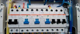
Be sure to remember that you are not alone in the stairwell. There are other users who are also happy owners of an electric meter installed in the panel. To avoid possible confusion, it is recommended that you number all circuit breakers that you have installed. Otherwise, you may face unpleasant remarks from your disgruntled neighbors.
Installing a meter in a garage is carried out in a completely similar way, with only one difference, which is that in garages there are ready-made separate power supply wires, which means there is no need to branch wires.
If you follow all the instructions and advice, as well as the available connection diagrams, installing an electric meter will not be difficult even for a user who does not have certain skills and proper experience. Such an installation does not imply too many difficulties.
Half wave converter
The device includes:
- Transforming device;
- Valve (semiconductor or vacuum diode);
- A capacitor that smooths out the transitions of the negative and positive half-waves;
- A resistor that acts as a load.
If you connect a half-wave converter to an oscilloscope, smoothed pulses will be visible on the graph. Signal softening is achieved through the use of a capacitor. During the negative half-cycle, the capacitor releases the electric current accumulated during the positive half-wave.
The disadvantages of this design include low efficiency due to the high level of vibrations. Therefore, half-wave converters are used exclusively in low-power systems.
Video: advice from an experienced electrician
In this video we will tell you how to make a single-line power supply diagram for a house based on a three-phase distribution board.
And if you have questions for the author of the article, feel free to leave them in the comments below.
Save time: selected articles delivered to your inbox every week
While working on electrical engineering, a person may come across symbols of elements that are conventionally marked on electrical wiring diagrams. The variety of electrical circuits is very wide. They have different functions and classifications. But all graphic symbols are conventionally reduced to the same forms, and for all schemes the elements correspond to each other.
An electrical wiring diagram is a document that indicates the connections between the constituent elements of different devices that consume electricity according to certain standard rules. Such an image in the form of a drawing is intended to teach electrical installation specialists so that they understand from the diagram the principle of operation of the device, and from what components and elements it is assembled.
The main purpose of the wiring diagram is to assist in the installation of electrical devices and instruments, simple and easy detection of faults in the electrical circuit. Next, we will understand the types and types of electrical wiring diagrams, find out their properties and characteristics of each type.
Electrical diagrams: classification
All electrical diagrams, like documents, are divided into types and types. According to the relevant standards, you can find a division of these documents by types of schemes and types. Let us analyze their detailed classification.
The types of wiring diagrams are as follows:
- Electrical.
- Gas.
- Hydraulic.
- Energy.
- Divisions.
- Pneumatic.
- Kinematic.
- Combined.
- Vacuum.
- Optical.
Main types:
- Structural.
- Assembly.
- United.
- Locations.
- Are common.
- Functional.
- Principled.
- Connections.
Considering the electrical diagrams, the listed designations, the type and type are determined by the name of the electrical diagram.
Symbols in electrical circuits
In the modern period, both domestic and imported elements are used in electrical installation work. Foreign parts can be represented in a wide range. In diagrams and drawings they are also designated conventionally. Not only the size of the parameters is described, but also the list of elements included in the device and their relationship.
Now you need to figure out what each specific electrical circuit is intended for and what it consists of.
Schematic diagram
This type is used in distribution networks. It provides full disclosure of the operation of electrical equipment. The drawing must indicate the functional units and their connections. The diagram has two types: single-line, complete. The single-line diagram shows the primary networks (power). Here is her example:
The full version of the electrical circuit is depicted in elemental or expanded form. If the device is simple, and the drawing includes all the explanations, then a detailed plan will suffice. For a complex device with a control circuit, measurement, etc., the optimal solution would be to depict all the nodes on separate sheets to avoid confusion.
Read also: TV bracket on the wall photo
There is also a schematic electrical diagram, which shows a copy of the plan with the designation of a separate unit, its composition and operation.
Wiring diagram
Such electrical diagrams are used to explain the installation of any wiring. They can depict the exact position of the elements, their connection, and the characteristics of the installations. The apartment wiring diagram will show the placement of sockets, lamps, etc.
This diagram guides the electrical installation work and gives an understanding of all connections. For the installation of household devices, this scheme is better suited for operation.
Combined scheme
This type of diagram includes different types and types of documents. It is used in order not to clutter the drawing and to indicate important circuits and features. More often, integrated schemes are used in industrial enterprises. For home use it hardly makes sense.
Having studied the symbols and prepared the necessary documentation, it is not difficult to understand the operation of any electrical installation.
Safety rules during work
Most of the rules are of a general nature, that is, they must be applied in the process of any electrical installation work.
If you decide to equip the electrical distribution panel yourself, before installing and connecting the RCD, do not forget:
- turn off the power supply - turn off the machine at the entrance;
- use wires with appropriate color markings;
- do not use metal pipes or fittings in the apartment for grounding;
- First of all, install an automatic input switch.
If possible, it is recommended to use separate devices for lighting lines, sockets, washing machine circuits, etc. Otherwise, installing a common RCD is sufficient.
To protect children, all electrical installations in a children's room are usually combined into one circuit and equipped with a separate device. Instead of an RCD, you can use a difavtomat
In addition to the characteristics of the devices themselves, the parameters of other electrical wiring elements are also important, for example, the cross-section of the electrical wire. It should be calculated taking into account the constant load.
It is better to connect the wires to each other using terminal blocks, and to connect to devices, use specially designed, marked terminals, as well as a diagram on the case.
Full-wave rectifier with zero terminal
A rectifying device with two diodes converts both half-waves of the signal supplied to it into a pulsed direct current. To convert the current, a transforming device is used, in which the secondary winding is divided into two halves. The central area is connected to the ground.
Principle of operation:
- With a positive half-cycle, a plus appears on one part of the transformer turns, and a minus on the second. The valve, which is connected to the positive part, conducts current. The second diode is closed. Passing through the resistor, the current hits the central point;
- With a negative half-cycle, the state of the windings changes. The second diode conducts current.
As a result, electricity is passed during both half-waves, and the efficiency reaches 90%.
Full-Wave Rectifier Voltage Filtering
The output we get from the full wave rectifier is a pulsating DC voltage that increases to a maximum and then decreases to zero.
To obtain a ripple-free voltage, we need to filter the output signal. One way to do this is to connect a capacitor, known as a smoothing capacitor, across a load resistor, as shown below:
Initially the capacitor is not charged. During the first quarter of the cycle, diode D1 is forward biased, so the capacitor begins to charge. Charging continues until the voltage reaches its peak value. At this moment, the voltage across the capacitor will be equal to Vp.
After the input voltage reaches its peak, it begins to decrease. As soon as the input voltage becomes less than Vp, the voltage across the capacitor will be higher than the input voltage, which will close the diode.
When the diode is not conducting, the capacitor discharges through the load until the next peak is reached. When the next peak occurs, diode D2 briefly opens and charges the capacitor to the peak value.
Let's move on to connecting the circuit breaker
If there is voltage on your supply wire, it must be turned off before starting work. Then make sure there is no voltage on the connected wire using a voltage indicator. For connection we use VVGngP 3*2.5 three-core wire, with a cross-section of 2.5 mm.
We prepare suitable wires for connection. Our wire has double insulation, common outer and multi-colored inner. Let's decide on the connection colors:
- blue wire - always zero
- yellow with green stripe - earth
- the remaining color, in our case black, will be the phase
Phase and neutral are connected to the terminals of the machine, ground separately to the feed-through terminal. We remove the first layer of insulation, measure the required length, and bite off the excess.
Remove the second layer of insulation from the phase and neutral wires, about 1 centimeter.
Unscrew the contact screws and insert the wires into the contacts of the machine. We connect the phase wire on the left, and the neutral wire on the right. Outgoing wires should be connected in the same way. After connecting, be sure to check again. Care must be taken to ensure that the wire insulation does not accidentally get into the clamping contact, as this will cause the copper core to have poor pressure to the machine contact, which will cause the wire to heat up, the contact to burn, and the result will be failure of the machine.
We inserted the wires, tightened the screws with a screwdriver, now you need to make sure that the wires are securely fixed in the contact clamp. We check each wire separately, swing it a little to the left, to the right, pull it up from the contact, if the wire remains motionless, the contact is good.
In our case, a three-wire wire is used; in addition to phase and zero, there is a grounding wire. In no case is it connected through a circuit breaker; a feed-through contact is provided for it. Inside, it is connected by a metal bus so that the wire passes without breaking to its final destination, usually sockets.
If you don’t have a feed-through contact at hand, you can simply twist the incoming and outgoing wires together using a regular twist, but in this case you need to pull it well with pliers. An example is shown in the picture.
The feed-through contact is installed as easily as a machine; it snaps onto the rail with a slight movement of the hand. We measure out the required amount of grounding wire, bite off the excess, remove the insulation (1 centimeter) and connect the wire to the contact.
Do not forget to make sure that the wire is well fixed in the contact clamp.
Suitable wires are connected.
If the circuit breaker trips, the voltage remains only on the upper contacts; this is completely safe and is provided for in the circuit breaker connection diagram. The lower contacts in this case will be completely disconnected from the electric current.
We connect the outgoing wires. By the way, these wires can go anywhere to a light, an outlet, or directly to equipment, for example, to an electric water heater or electric stove.
We remove the outer insulation and measure the amount of wire required for connection.
We remove the insulation from the copper conductors and connect the wires to the machine.
Prepare the ground wire. We measure out the required amount, clean it, connect it. We check the reliability of fixation in contact.
The connection of the circuit breaker has come to its logical conclusion, all wires are connected, and voltage can be applied. At the moment, the machine is in the down position (off), we can safely apply voltage to it and turn it on, to do this we move the lever to the up position (on).
By connecting the circuit breaker with our own hands, we saved:
- calling an electrician - 200 rubles
- installation and connection of a two-pole circuit breaker - 300 rubles
- DIN rail installation - 100 rubles
- installation and connection of a feed-through grounding contact 150 rubles
TOTAL: 750 rubles
*The cost of electrical installation services is shown in the pricing table