Today, very often, private houses are connected to a three-phase electrical network. Also, in some new high-rise buildings, apartments began to have three phases instead of one as before. As a rule, with this connection, local network companies allocate 15 kW of power per house or apartment. This means that the rating of the input circuit breaker should be 25 A. For small offices, cafes, etc. release more power. Therefore, in their shields the ratings of the introductory machines will be completely different.
Connection to a 3-phase electrical network requires the installation of three-phase electrical panels. Below we will look at five different options for simple three-phase circuits for a distribution board.
All schemes are simple and are advisory in nature. They clearly show the essence of the connections of different protective devices in one panel. The development of the design of each shield must be approached individually, since everyone’s conditions are different. The grounding system in the presented versions is TN-S.
The need for three-phase connection
In a single-phase network, often the only phase is overloaded due to the use of powerful units , which are becoming more and more common in modern homes. As a result, connected electrical appliances fail, creating an emergency situation that threatens a fire.
At the entrance to the house there are always three phases, which are distributed in a phase-zero set. Pairs power groups of loads of equal power. If a residential building is allocated 15 kW of power, then each group receives no more than 5 kW. If the rule is not followed, the circuit breakers will trip if the line is overloaded.
If consumers in the house require a total of more than 15 kW, a three-phase connection is needed
Equipment requiring a three-phase line connection:
- an electric heating boiler in a large house can take about 9 kW;
- water pump operating in a deep well;
- electric stove for baths, high-power saunas (from 5 kW);
- hob, oven;
- equipment for a private workshop at home, for example, milling and lathes, a circular saw, a welding machine, a jackhammer.
Such units can be found with a 220V connection, but 380V is more reliable, more powerful, and more economical . Modern devices for everyday use can be designed specifically for 380V, for example, a motor on a garage door or entrance to a yard.
Three phases are needed if there are three-phase motors on the site that are not designed to operate in single-phase regulation. Alternatively, the organization of such input is necessary when many electrical appliances are used at the same time, for example, a household has been developed, private production has been established.
They try to supply a three-phase power line to every private building, and the user can use it or not as he wishes.
Pros and cons of three-phase connection
Economical use of electricity
Low material consumption of transformers and power cables
Even load distribution
Synchronous and asynchronous current motors show high efficiency
It is possible to obtain simultaneously linear and phase voltage in one installation
Probability of reducing lamp flicker and stroboscopic effect of fluorescent lamps
In the event of an accident, one or two phases burn out, but for power supply there is the possibility of a temporary backup connection
Three phases are required if there is not enough single phase line, but in this case it is easier to request an increase in the limit
It is necessary to distribute the load evenly between phases
A new switchboard and accessories are required
The danger of electric shock increases, since the network contains not only single-phase voltage, but also linear
Calculation of energy consumers
Before distributing the load across phases, it is recommended to perform a preliminary calculation of consumers. This can be easily done by making a list of potential sources that will be assigned to a particular phase. For example, list the main household appliances and their power as stated by the manufacturer:
- Electric hob 6.5-7.5 kW.
- Washing machine 1.5-1.8 kW.
- Dishwasher 1.5-1.8 kW.
- Microwave oven 0.9-1.2 kW.
- Oven 2.0-2.6 kW.
- Vacuum cleaner 1.9-2.2 kW.
- Iron 1.9-2.2 kW.
How to properly divide energy consumers into several groups Source uk-parkovaya.ru
Important! If necessary, the list can be supplemented with other electrical appliances on the balance sheet.
Requirements for connecting 380 volts
The rules for connecting the site are prescribed in the text of Federal Law No. 35 “On Electric Power Industry” dated March 26, 2003 (Articles 20 – 26), edited on December 27, 2019. The work of electric grid companies is regulated by Federal Law No. 135 “On the Protection of Competition” dated July 26, 2006.
Example specifications
Basic Rules:
- the user cannot independently connect electricity to the house; an energy supply organization is needed;
- connection is possible after fulfilling the requirements of the technical specifications;
- use cables with aluminum (not less than 16 mm²) or copper (not less than 10 mm²) conductors; armored cables are laid underground;
- with an aerial connection, the cable does not sag below the road below 6 m, above the sidewalks - below 3.5 m;
- the underground line is buried 0.7 - 1 m or lower;
- entry into the dwelling - not lower than 2.75 m from the ground;
- devices installed upstream of the electricity meter must be sealable.
In a 380V network, it is allowed to connect a three-phase meter in a private house with a maximum current strength of 50A, accuracy class - 2, last check - no more than 1 year ago. It is fixed on the DIN rail of the distribution panel, but it can be located outside the switchboard. The house must have a grounding system.
How to apply for a permit
The consumer has the right to connect to any electrical facility within 300 m from the site (power line supports, transformer substations, cable lines). The contract is concluded for a new connection, increasing power or moving the entry point.
List of project documents:
- site plan in the general layout of the development;
- connection diagram for power receivers;
- internal wiring diagram;
- PPR for connection.
The application is written at the company’s office, or submitted in your personal account through the website.
Information to be submitted with the application:
- Full name of the applicant;
- address of the connected site and the actual location of the user;
- project development period and commissioning time;
- power separation between phases;
- highest required power;
- type of load.
The company must meet deadlines for making decisions on the application. For individuals with a required power of up to 15 kW, this period is equal to 15 days, with other indicators or for a temporary connection - up to 30 days. After signing the contract, the specifications are given, which the user must exactly carry out on his site.
The owner notifies the company about the completion of preparation; in response, the electrical network checks the compliance of the specifications and the actual work in the presence of a representative of the supplier’s supply organization. A certificate of compliance is drawn up (within 3 days), the owner of the site signs the document within 5 days. This is followed by: an agreement on technological connection, an agreement on the supply of electricity. After this, 380V is supplied to the site.
Single-line power supply diagram 15 kW - cable or wire?
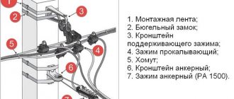
The SIP4 4x16 wire is intended for 0.4 kV overhead lines, has the required mechanical strength and can withstand a long-term current load many times greater than that corresponding to 15 kW. In principle, it can be replaced with a cable like AVVG 4x16... however, since it is not intended for overhead lines and does not have the necessary mechanical strength, it can only be used on spans by hanging it from a steel cable. Although, I saw that in the village. Mirror (LOESK territory), such a cable was used for lowering from VL-0.4 to the shields along the support. However, SIP4 4x16 has become a de facto standard and is often included in the technical conditions for connection to power grids.
Selection of materials and equipment
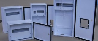
Input components and the meter are placed on the distribution panel, the dimensions of which are determined by the number of connection points. Metal boxes with protection from moisture are placed outside, steel and plastic cabinets are used inside.
Set of components for connection:
- corrugated tubes, self-extinguishing or non-flammable cable ducts;
- copper cable VVGng;
- three-phase meter;
- connecting switches: combs, buses, terminals;
- protective and safety fittings;
- automatic circuit breakers complete with RCDs or combined automatic circuit breakers;
- a relay that protects against voltage surges in the circuit.
A DIN rail is prepared for high-quality fastening of automatic machines and protective devices; mounting spaces for these devices are provided on the bar.
To carry out internal wiring , you need wires, boxes for changing the direction of wiring, socket boxes and for switches.
You will need alabaster or plaster to fix the cables in the wall grooves, clamps, electrical tape, and adapters.
Single-line power supply diagram 15 kW - surge suppressor
In order to protect the subscriber's electrical installation from surges, a surge suppressor is used. The last sentence of paragraph 7.1.22 of the PUE speaks for its use. In principle, one can argue about its use, saying that the metering board is not an input device. However, pay attention to the name of the panel “Input distribution device”. Representatives of network companies usually do not oppose such protection of electrical installations. On the contrary, they welcome her. “Forum luminaries” who do not have sufficient experience of joining and do not understand the meaning of many points from the PUE may speak out against it.
The entry looks like this: “OPS1-B-3p surge suppressor with sealing option.” An IEK surge suppressor for 3 phases with a threshold voltage of 400 V is used.
Input of three phases into the building and outgoing lines
Electricity from the pole is connected to the building through the air or underground.
All conductors are connected to the electrical panel, then the electric current enters the meter and passes to the distribution unit. Here the working zero and the grounding wire are separated, they are connected to the grounding bus, which is connected to the repeated grounding branch. Formation of outgoing lines :
- additional circuits come from the input switchboard (VRS);
- an introductory switch is installed in it, all phases are connected to it;
- circuit breakers are installed for each group circuit in the home, each of them is powered from different phases;
- groups are formed according to the power of units and devices so that each phase has approximately equal value;
- three phase conductors and a neutral conductor from the grounding bus are connected to the meter contacts;
- the meter output is connected to a common circuit breaker for the entire house.
Valera
The voice of the construction guru
Ask a Question
For connection, use the triangle or star method. The first method is to connect the phases sequentially: the end of the first to the beginning of the second, the end of the second to the beginning of the third, and so on. Star - when the ends of the phases are joined at a common point and the ends of the phases of consumer windings - also in one place.
Electrical 380V electricity metering panel for a private house with a 220V socket
In this electrical panel diagram, there is additionally a modular 220V socket (number 7) with an individual protection device - difavtomat (number 8), which combines a circuit breaker and a residual current device. The rating of the RCD must be higher than that of the circuit breaker, for example 40A, leakage current 100 or 300 mA.
Electrical metering panel 380V, with modular socket, TN-CS grounding
Electrical panel assembly
The input switch and meter are sealed by power grid workers, so they are located at the beginning of the switchboard so as to provide this opportunity.
Step by step assembly:
- fastening of automatic devices and RCDs on the rail according to the drawn up diagram;
- connecting elements to the input switch using a comb;
- connecting phase wires with wires with lugs;
- installation and connection of the zero bus;
- checking (tightening) joints with a screwdriver;
- turning on the power, checking the operation of the machines;
- determining network parameters using a multimeter.
Before starting to operate the 380V network, make sure that all elements of the internal system (sockets, sockets, switches) are installed and connected.
What are the types of 1-line electrical circuits?
If we consider a single-line power supply diagram from the point of view of its purpose, we distinguish:
- calculation diagram, which is made at the stage of development of design documents; it will serve for future calculations of the parameters of the energy supply system, and it is this that will be considered by the relevant authorities before issuing the Technical Specifications;
- the executive diagram is made already at the stage of operation of the facility, when it is necessary to make changes to the network configuration (changes in group and main lines, new capacities, modernization).
All electrical circuits - structural, functional, installation, circuit diagram of power supply - are designed on the basis of single-line ones.
Connecting sockets
The peculiarity of 380V sockets is that they block from asymmetrical connection to avoid short circuit. The contacts are placed at an angle, they are different in size, with guide elements.
Stationary 380V sockets are produced in the following types:
- 2P+PE has two power (phase) terminals and a grounding terminal;
- 3P+PE or 3P+N is characterized by three phase terminals and one for grounding connection;
- 3P+PE+N - there are places for connecting three phases, one for zero, one more for grounding.
The sockets are interlocked to prevent switching off under load. The current strength (25, 63, 125A) for which these sockets are made is significant, and the products do not have an arc-extinguishing effect. Removing plugs under such a load is dangerous in terms of burns or burnt out sockets. The lock can be of an electronic or mechanical type.
Sockets are connected to the power cable in series, parallel or in a mixed way.
How to make a line diagram?
Let's start with what information needs to be conveyed on the diagram.
- Balance sheet area: which area falls under the responsibility of the electricity supplier, and for which boundaries the consumer is responsible. This data is included in the facility’s energy supply contract.
- ASU (main switchboard), transformer substations with AVR devices, autonomous power supply - if available.
- Meter with conversion ratio if the secondary operating current is 5A.
- All distribution cabinets for power equipment and lighting.
- Duration of highways with the method of laying cables and wires, with markings.
- AV, RCD and fuses are in working order with technical specifications.
- Loads going to electrical equipment with a prescribed current, power, cos ϕ.
If we consider the project in stages, we must first apply for technical specifications (a request is made to obtain specifications). This is followed by the immediate development of the scheme and its approval.
The process is regulated by the following standards: State standards 2.709-89, 2.755-87, 2.721-74, 2.710-81. All of them belong to the ESKD (Unified System of Design Documentation), and reveal conventional graphic and alphanumeric designations of various parts of single-line power supply diagrams. Examples of notation:
- cabinets and boxes;
- measuring instruments;
- connecting wires and crossing lines.
The easiest way to design diagrams is to use ready-made software on your computer: AutoCAD Electrician, Compass-Electric, DipTrace, Eagle, 1-2-3 diagram, Microsoft Visio.
Electrician's recommendations
For hidden wiring, built-in electrical panels are chosen, and exposed wires are connected in overhead distribution panels. The shield body is placed so that it can be easily reached.
Electricians advise observing the following conditions:
- horizontal sections of wires from the panel to the sockets are made at a height of 2.5 m from the floor;
- wiring in the walls is placed vertically or horizontally; it is prohibited to install it along an oblique line;
- connect the wires with adapters in installation boxes;
- the underground connection to the power pole is made with a single piece of wire without connections;
- Do not connect the switch to the neutral wire;
- When laying on wooden walls, insulating hoses with asbestos linings are used.
The distribution housing is selected according to the type of room, taking into account the characteristics of the microclimate - in aggressive environments, boxes with maximum protection from direct water jets and dust are used.
