Connecting a private home to the electrical network involves installing a metering panel in which an electricity meter and protective devices will be mounted, an input from the electrical network and an outgoing cable that powers the home wiring will be connected. Often, one of the requirements of the supplying organization that connects to electrical networks is the installation of a metering panel on a support (pole). In this article we will provide readers of the Sam Electric website with basic recommendations on this issue.
Classification of shields
The metering board can have different designs: in the form of a small box designed for installation of a metering device and a protective device, or in the form of a full-fledged cabinet in which several protective devices and other auxiliary elements for the distribution of electricity can be installed (metering and distribution and group metering). distribution boards).
Shields are also classified according to the degree of protection of the housing from the negative effects of moisture and foreign objects, including dust. In this case, the shield is installed on a support (pole), that is, outdoors, so the body of such a shield must have a protection degree of at least IP54. Also, when choosing the housing of the metering and distribution panel, you need to take into account the possibility of its operation in the temperature range of local environmental conditions.
The housing of the metering board for installation outdoors must have a locking device, and on the housing itself there must be a transparent window to allow energy sales representatives to easily take readings.
Electricity metering panel for a private house: diagram, assembly, installation
Introduction
The issue of connecting a private home is one of the most discussed on the Internet. One of the reasons for such popularity is the division of connection work between the home owner and the operating organization. So the owners are looking for how to do their part of the work correctly. Fortunately, there is useful and practical information and here you can find excellent information assistants. In this article we will talk about an electricity metering panel for a private home.
Owner connection activities
By connecting a house to power lines, the owner of the house receives technical conditions for connection. It has a section that lists what the owner must do to connect.
I will give an excerpt from such a technical specification. The owner is obliged to install a metering unit with protection devices for power receiving devices, 25 Ampere circuit breakers that control the amount of power and an electricity consumption meter with accuracy class 2.0.
Let us clarify what is meant in this specification and how to implement this requirement.
Outdoor electricity metering panel for a private house
Whatever disputes arise regarding the location of the metering board installation, the preferred location for energy companies remains an outdoor location with free access for supervisors.
This means that we will need a power metering panel for street installation on a pole (support) with a housing protection level of at least IP54.
You can assemble this shield yourself, or purchase a ready-made version from the manufacturer.
Shield diagram
You need to assemble the electricity metering panel of a private house according to the diagram. Here is one version of it, which can be called generalized and recommended.
On the circuit diagram of the shield we see:
- A branch from a 0.4 kV overhead power line support is made with a self-supporting insulated SIP wire 4×16, which means four cores in total insulation with a cross-section of 16 sq. mm.
- On the input side, the shield is protected by a common three-pole 50 Ampere circuit breaker.
- The electricity meter has an accuracy class of 2, and is designed to operate in a network from 5 to 60 Amperes.
- Electrical energy is distributed into several groups: two three-phase (380 V) at a power of 32 Ampere and 20 Ampere, and one single-phase 220 V at 10 Ampere.
- The switchboard itself must be provided with a grounding system made in accordance with the standards. The panel body, as well as the busbar for connecting the PE protective wires, must be connected to the grounding loop made for the installation pole.
Assembling the metering board
It’s not difficult to assemble such a shield yourself.
It is important to follow a few simple rules: . Input and output wires should not touch the metal body of the switchboard and should not press on each other
For this purpose, all passages through the housing are protected with plastic sleeves and are sufficient for free passage of the cable.
The installation wires inside the switchboard should not intersect, especially at angles other than 90˚.
All wire connections to the PE bus must be visually visible, and the tightening screws of circuit breakers and terminal blocks must be accessible for tightening.
To avoid temporary weakening of the connections of wires and busbars, they must be made not only through a washer, but also reinforced with a locking washer (DIN 127).
- The input and output wires should not touch the metal body of the switchboard and should not press on each other. For this purpose, all passages through the housing are protected with plastic sleeves and are sufficient for free passage of the cable.
- The installation wires inside the switchboard should not intersect, especially at angles other than 90˚.
- All wire connections to the PE bus must be visually visible, and the tightening screws of circuit breakers and terminal blocks must be accessible for tightening.
- To avoid temporary weakening of the connections of wires and busbars, they must be made not only through a washer, but also reinforced with a locking washer (DIN 127).
Installation of metering board
The metering board is installed on the street at a height of 1200-1600 mm, on a pole (support) indicated as the input one. The descent of wires to the switchboard and the lifting of wires from the shield are carried out in pipes or boxes or openly on clamps. The descent of wires from the switchboard to the house in a trench is carried out only in a pipe with the pipe turning into the trench.
Grounding the metering board
The metering board is grounded locally. A wire of at least 10 mm or a metal strip is laid from the shield down the pole with secure fastening to the pole with clamps.
For the grounding itself, the reinforcement of a concrete support or a separate pin driven into the ground to a depth of 1.8-2.0 meters is used until the standard grounding resistance is reached, 4 Ohms for 380 V and 8 Ohms for 220 V (PUE 7, 1.7.101.)
E
Information for gardeners
An open request for proposals was announced in electronic form No. 126e dated 08.14.18 for the supply of a complete two-transformer substation 2KTP 250/10/0.4 kV, size 6650x7200 with 2 (Two) power transformers TMG 250/10/0.4 kV Y/Y- 0, according to the questionnaires and technical specifications (Appendices No. 2, No. 3 and No. 4).
An open request for prices in electronic form No. 125e dated 08.08.18 has been announced. for the purchase of cable ASBL 3x150 10 kV.
An open request for quotations No. 122 dated 08/06/18 was announced for the implementation of work on laying a case for an electrical cable using the HDD method at the facility: “CL-1 kV from RU-0.4 kV TP-31 for power supply to the power receiving device of a non-residential building with cadastral number 58:29 :4005011:51, Penza, st. Belinskogo, 8" (project code 151-07-18-ES)
An open request for proposals was announced in electronic form No. 123e dated 08/07/18 for the supply of ASBL cable 3x240 mn 10 kV (reconstruction of 2KL-10 kV substation 110/10 kV "Novokazanskaya" - RP-19)
An open request for prices has been announced in electronic form No. 124e dated 08/06/17 for the supply of: No. Name Quantity Minimum construction length Unit. change Product requirements1 Cable AVBShv 4x240 1kV (technical connection Penza, Ladozhskaya St., 1B) 410 205 m GOST 31996-2012
2 Cable AVBShv 4x240 1kV (technical connection Penza, Belinsky St., 460 230 m GOST 31565-2012
Electrical panel design
Electrical panels used to supply power to country houses and cottages have the following components:
· electricity meter;
· zero bus;
· RCD;
· grounding bus;
· several automatic machines (introductory, for high-current and low-current sockets, for lighting devices).
The complete set of the switchboard, as well as its installation, should be entrusted to an experienced electrician. The presence of errors in this case is unacceptable.
We are developing a scheme
In order to organize a grounding device for a private house, it is necessary to work out a grounding circuit diagram. The most popular and most frequently used is the triangle diagram.
As a rule, 3 electrodes stand at its vertices; you can add additional ones, which are driven in a straight line between the vertices.
If it is impossible to make such a contour, the electrodes can be installed in a line, rectangle, semicircle or wave. But it should be noted that the triangular ground loop scheme is much more efficient.
How does the work of installing an electrical panel on a pole proceed?
1. Selecting a support for the shield. Installation can be carried out on an existing pole, having received permission for this, or by concreted a new one. The support must be strong, rigid and free from significant mechanical damage.
2. Marking the post. The master performs calculations and lines the surface of the support, checking the size of the metal cabinet.
3. Fixation of the bracket. The structure must wrap around the pole. The shield body is attached to its ends using bolted connections.
4. Installation of DIN rails. They are necessary for attaching neutral and grounding busbars, electric meters and automatic machines.
5. Installation of equipment. The master connects the input cable, installs the circuit breakers, zero and grounding buses, groups of fuses (connected to each other using jumpers), and an RCD.
After completing the installation of the electrical panel, electricity is connected. The master makes a control assessment of the quality of work.
Organizational matters
First of all, it should be taken into account that the electric grid company makes a connection directly to the power grid only if all requirements for installing a metering panel and completing all necessary documents are met.
Therefore, the first stage is drawing up a project and approving it in the power grid organization. As a rule, an organization has standard designs for connecting to electrical networks and a list of requirements regarding the selection of the rating of protective devices, the type of electric meter, the cross-section of the input wire (cable), the type and design of the housing of the metering and distribution panel, as well as requirements for mounting the panel itself on a support or in the other place. It is possible that, at the request of the supplying organization, it will be necessary to connect the meter to an automated commercial electricity metering system (ASKUE).
Situations often arise when, after purchasing an input cable, installing a switchboard, metering device and the necessary protective devices without prior approval, the energy supply organization refuses to connect to the power grid and you have to correct installation errors or re-purchase a new electric meter, protective devices and other elements.
Therefore, if you already have a ready-made project, then before purchasing the necessary structural elements and proceeding with the installation of the electrical panel, you should agree on the project with the supplying organization.
Types of boxes by type of design
Foreign and domestic manufacturers offer boxes of different sizes and capacity. The option is selected depending on the parameters of the equipment that is planned to be placed in the box.
The dimensions of the shield are also selected for the type of meter. Single-phase metering devices are smaller in size than three-phase ones, sometimes two times
There are also certain markings that indicate the type and purpose of the box. Example:
- Control panel is the usual and simplest one;
- ShchVR - a box built deep into the wall;
- ShchRN - distribution-mounted box.
If it is just a metering panel, it usually contains only a meter, an input machine, grounding and neutral buses. Residual current devices, as well as circuit breakers, are installed in the “home” box. But you can combine all this in one box.
The design of the shield can be:
- floor;
- built-in;
- invoice or mounted;
- hidden or open;
- whole or collapsible.
What kind of equipment, in what quantity and with what parameters should be installed in the box - all these points are prescribed in the power supply project for a private house. If there is no such document, you need advice from relevant specialists.
Subscribe to the newsletter
The standard home grounding system is quite simple: a ground loop is installed in the yard or basement, from which a conductor is drawn, connected to the home metering panel, or more precisely to the ground bus (PE) on it. From this bus, ground wires extend to outlets, bathroom hardware, and other objects that need to be grounded.
In this case, the grounding of the metering panel (board) is often overlooked. The electricity metering panel is a box that houses the meter, automation, RCD, zero bus, ground bus, etc. At the same time, the direct internal placement of the PE bus does not yet guarantee full grounding of the metering panel (board), since this must be done correctly.
To ensure that the grounding of the metering panel (board) is stable and complete, the PE bus can be mounted directly on its body, which has previously been cleaned of paint, varnish, dust and dirt at the contact point. In this case, more reliable grounding will be obtained if a separate grounding conductor is connected from the PE bus to the switchboard body.
Figure 1. Example of proper grounding of an electricity metering panel
It is worth noting that the electricity metering panel contains all the equipment for supplying and metering electricity, as well as means of protecting against network faults, so the safety of the electrical panel must be taken with full responsibility. Reliable grounding is one of the factors of such safety.
To install a subscriber branch to a private home, it may be necessary to install an electrical panel on a pole. In this case, the main switchboard, where the input machine and metering meter are located, is fixed directly to the power line support.
Basic criteria for choosing a box
The main task of the consumer is to find a durable, practical box that will withstand long-term service in outdoor conditions. The box should be convenient for installation and operation.
What is important about the design itself? The presence of holes of the appropriate diameter for the wires that come from the support and lead out to the building. It is desirable that these elements have rubber seals and plastic couplings.
The electrical panel must accommodate all necessary outgoing cables and additionally leave space for upgrading or expanding the installation
A convenient detail is the window. It eliminates the need to open the shield to take readings and reduces the frequency of contact of the internal contents with air and moisture. Pay attention to the sealing lugs.
Another important point is the degree of protection from dust and humidity. It is determined by the IP index and the number next to it
The IP20 index means that the box is protected from dust particles larger than 12.5 mm, but is vulnerable to moisture. The IP65 protection degree guarantees complete isolation from these negative factors. The higher the number, the more expensive the design. The optimal option is with a score of 54.
When choosing an electrical panel, you also need to look at the thickness of its walls, operating temperature range, number of doors, and type of lock. The box can be locked with one individual key or equipped with several identical ones.
Design and purpose of grounding devices
Such structures are divided into working and protective devices.
- The worker is used to organize the safe operation of industrial units. Also common in private households.
- A protective grounding system is required for electrical networks in the residential sector.
Installation of a grounding device (GD) is required in accordance with the Rules for the Construction of Electrical Installations and the Rules for the Operation of Consumer Electrical Installations.
People touching live parts exposed as a result of improper operation of electrical equipment, design defects, deterioration of insulation and other reasons is common. Poor-quality design of the charger and its installation can lead to serious consequences for people: electric shock, burns, disruption of the heart and other human organs, electric shock often leads to amputation of limbs, disability and even death.
The grounding system consists of external and internal parts, which are joined in the electrical panel. An external grounding device consists of a complex of metal electrodes and conductors that drain emergency current from electrical equipment into the ground in places that are safe for people. The electrodes are called ground electrodes. Electrical conductors are grounding conductors; they are pins 1.5 m long and 1 mm in diameter.
They are manufactured industrially from copper or copper-plated steel. Their main advantage is increased current conductivity. They are driven into the ground with hammers or sledgehammers to a depth of 50 cm; contact with the ground must be as strong as possible, otherwise the structure’s ability to drain current will deteriorate.
The simple design is made from a single electrode. Used in lightning rods or to protect remote objects and equipment. In individual farms, preference is given to multi-electrode devices. They are placed in one row and are called linear memory profiles. The standard chain length is 6 meters. They are connected to each other using brass couplings; the fastening is threaded; welding is not recommended. Grounding conductors are installed through terminals. Twisting and soldering of cores are excluded.
Read also: How to make a knife from a circular disk
A device such as a ground loop (closed version) is still common. It is constructed at a distance no closer than 1 meter and no further than 10 meters from the house. Placed in a trench in the form of an equilateral triangle. Side length 3 m, depth – 50 cm, width – 40 cm. Grounding conductors are driven into the corners. The same operation is performed with other vertical electrodes (no more than five units). Grounding conductors in the lower supporting part are welded to horizontal products.
They are made of copper, copper or zinc coated steel angle (5 mm flange, 40 mm strip). A standard stainless steel angle of any profile is often used. The products are not painted, as in this case the electrical properties will deteriorate due to weakened contact with the ground.
The design of the circuit is simple; you can do it yourself. But the work is simplified when using ready-made grounding devices on the market, complete with grounding wires. Financial losses will be recouped through the use of high-quality materials that are resistant to corrosion and have a long service life.
DIY wardrobe
If you have experience and desire, you can arrange a cabinet for an electric meter yourself. You will need to buy the structure itself, arm yourself with the necessary tools and assemble the electrical panel in accordance with the specifics of the home electrical network.
If you come across a cabinet of the required dimensions, but it lacks a window, lugs for seals or some holes, it is permissible to add these elements. But the work must be carried out in accordance with safety regulations and the requirements of regulatory organizations.
All necessary equipment is mounted on DIN rails. Many models of metering devices come with parts that may be useful during installation (stickers, caps, fasteners). The main task is to assemble the devices and connect them correctly with each other.
Models of external meters
If you are buying a new meter and not removing the existing one from the premises, you need a device suitable for use in outdoor conditions.
Please note the following points:
- Induction models are much more sensitive to temperature changes than electronic ones.
- DIN rail is preferable as a mounting method.
- Go to the website of the electricity sales organization and see which models are allowed for installation in Russia.
- For a multi-tariff payment system, choose a device that can take into account more than three tariffs.
Don't miss: 6 best manufacturers of inspection hatches
Brand recognition and the presence of service centers also matter. A trusted manufacturer means quality, maintainability, and loyalty of inspection organizations.
Consider purchasing a counter and a box from the same manufacturer: this will make it easier to fully integrate the devices and the shell
Among the commercially available domestic brands, we can consider the following: INCOTEX, Taipit, Energomera, EKF. Particularly popular is the model “Mercury” 230 AM-03. It has a single tariff and is capable of giving accurate readings at temperatures ranging from -40 to +55 degrees.
Of the foreign manufacturers that have proven themselves well: Swedish-Swiss ABB, French Schneider Electric, Turkish Legrand. But European brands often have operating temperature ranges that do not correspond to Russian realities.
It is advisable to consult with specialists from the service organization in your region. Usually they have a list of devices that have already shown their best performance during operation.
Automatic and heater
An automatic switch is installed in the box before the meter. Its parameters must be calculated from the total power of all consumers - electrical appliances installed or planned in the house and on the street/garage and other domestic buildings.
If, for example, the total power is 25 kW, then a 63 A automatic machine is optimally suitable for this value. In addition to the input one, you need an outgoing line automatic machine, protective for the heater and modem (if any). Using the latter, the readings are automatically transmitted to the processing center. But such a scheme cannot do without a heater.
The heater for the electrical panel can be turned on and off manually or automatically. It is needed to maintain optimal temperature in cold weather - electrical appliances need heat to work without errors
Heaters for electrical panels are made of aluminum, which is coated with non-flammable thermoplastics.
The main functions of the element are to prevent the appearance of condensation, which prevents corrosive changes in current-carrying busbars and contacts and protects devices from high humidity.
Transfer input device and SPD
If the electrical installation includes an autonomous power source, a backup device must be installed after the meter. This device is needed to manually switch consumers from the external network to the generator and back.
The reserve input device eliminates the simultaneous use of two different power sources (external network and generator), which is its task
To protect the installation from lightning strikes, high-voltage surges and fires from these impacts, an SPD (surge protection device) is added to the panel. It is placed after the input circuit breaker and through a separate fuse. An SPD is required if entry into the building is carried out via an airway.
Additionally, a fire protection RCD and a cross-module for distributing electricity to different groups of consumers can be installed in the panel. Sometimes a differential machine is also added to the box.
The socket is one of the optional elements. But if construction is just underway on your site or you need a street connection for some equipment, you can’t do without it. And don’t forget about the zero rail, it combines all the zero cables and is used for connecting cores.
What and how to ground
First group. On the back wall of these devices you can find a special terminal, usually a screw terminal, for separate (direct) grounding of the housing.
Most likely, there will be no mention of it in the instructions for electrical appliances, since its presence automatically transfers the device from the class of household to industrial devices.
But despite this, many manufacturers place it on:
- Washing machine (sometimes dishwasher). It definitely needs to be grounded through a Euro socket, since it has a large electrical capacity and is most often installed in a damp room.
- Microwave. The working source of wave radiation in it is a powerful magnetron, and even with minor wiring defects or poor contact in the socket, it is capable of breaking through.
It is not necessary to trust the installation and connection of a power outlet for an electric stove to specialists; the main thing is to have detailed instructions on hand that will help you figure out what and how to do.
You can learn more about installing and connecting an electric meter by reading this article. After this, you can connect an electric meter with one or three headlights yourself.
Second group. For safety reasons, it is advisable to ground them.
- Induction hob (electric hob) and electric oven. The internal wiring in them operates at high temperatures, and the power is quite high.
- Desktop computer. If you ground the computer's power supply directly (at any screw on the rear panel), this will eliminate not only periodically occurring floating potentials, but also some “glitches” of the computer. Even the Internet speed may increase.
- Hydromassage boxes (especially with steam generators). Manufacturers from China did not bother to worry about safety, so it must be grounded directly from any metal fastening under the pallet.
Select a counter
All meters that can be installed to account for energy consumption are classified according to three criteria:
- Device design;
- How to connect it;
- Type of measured quantities.
Currently, two types of devices are installed in apartments, private houses and SNT: electronic, which records and controls consumption at differentiated rates, and induction, which makes measurements by rotating the disk.
The second option is not very reliable, so it is gradually being replaced by electronic ones.
Induction and electronic meters
Electronic devices are best suited for outdoor installation, as they are convenient and accurate and do not react to temperature changes. However, operating conditions with a temperature of 40 degrees below zero are the ceiling for them, and in regions where such weather occurs, it is still better to install meters indoors.
How to buy an electronic meter
The most important element for the meter is the seal. After leaving the assembly line and passing quality control, two of them are installed: the first is installed by the quality control inspector, and the second is installed by the state representative authorized to carry out verification.
Places for installing seals
The date of verification is put on the seal and entered into the product passport, so the first thing you need to do when purchasing is to check them.
If it suddenly turns out that there is no verification seal, or there is a date on it that does not correspond to the one in the passport, we do not recommend buying the device. Then you won’t be able to prove anything to anyone.
Verification seal
The date of verification is also important. At the time of purchase of a two-phase meter, it should not exceed two years, and for a three-phase meter this period is completely reduced to one year.
You can find all the necessary data in your passport
Is it possible to separate the PEN conductor after the energy meter?
Is it possible to separate the PEN conductor after the energy meter?
Post by Serex » 02 Aug 2021, 01:27
I’m trying to justify my point of view regarding the connection to the overhead lines (OHL) of my building. Now connected: a branch from the overhead line 4 wires - 3 phases and PEN are inserted into the energy metering panel. The panel has a 3p machine and a counter. There are no N and PE tires. The shield is not grounded, although it is metal. After the meter, 4 wires go to my building.
The problem is that the electrician who connected all this is suggesting that I make a TT grounding system, despite the new poles and insulated SIP cables on the poles as an overhead line and a new building. I would like a TN system, which is considered more reliable.
Selection of materials for installation
The implementation of the 15 kW specification consists of installing a meter on a pole at the border of the site. The electricity metering circuit is assembled in the switchboard. We were faced with the task of choosing an electrical panel that was protected from atmospheric influences, as well as from corrosion.
Plastic electrical panel for TU 15 kW Electrical panel for street installation Outdoor plastic electrical panel
In this work, we used an electrical panel made of plastic cross-linked with fiberglass. The advantages of such an electrical panel when performing 15 kW specifications:
- Protection against moisture and dust IP 67
- Corrosion resistance
- Rugged housing
- Ease of installation
- Sealed cable entry
- Low price
- Stylish design
The cable entry is made using sealed leads, which provides protection from moisture.
Circuit breakers were selected based on safety and reliable operation, as well as workmanship. ABB machines meet these parameters.
Meter Mercury 231 AT 01 I, multi-tariff 3-phase for current 60A.
Box for 4 modules for sealing the power supply organization. Mounting wire Pv1 with a diameter of 6 mm.
The cable used is SIP 4 4*16 wire, as well as SIP fittings for its installation. Anchor clamp SIP DN 123 and branch clamp P 645.
The bracket is made of metal perforated profile 40*20. The profile is secured using pins with a diameter of 8 mm.
Grounding circuit without welding in country conditions
Not all owners of summer cottages have the opportunity to perform welding work. At the same time, there are requirements to connect the elements of the ground loop only by welding. You can do it differently: prepare grounding pins where it is possible to weld a galvanized bolt to each of them.
Grounding diagram at the dacha
On a summer cottage, to install a grounding loop, you first need to dig a 0.5 m deep ditch next to the house. Now all that remains is to hammer the pins into the bottom of the trench and connect one whole grounding wire with a cross-section of at least 10 mm2 to all of them. The joints should be treated with anticorrosive and wrapped with several layers of electrical tape.
The resistance of the finished circuit, of course, needs to be checked.
Another way to ensure grounding without welding is to purchase a special ready-made set of copper-plated rods. Such a kit costs a lot, which will not suit everyone.
Examples of grounding connections without welding
In this case, it is quite possible to purchase galvanized pipes of small diameter, flatten and make one end sharp. Such rods are driven into the ground according to the above plan. You can connect to them using galvanized clamps with a clamping bolt, which are also commercially available. The joints should be treated with anticorrosive and wrapped with several layers of electrical tape.
Thus, we examined the features of arranging grounding in a country house with our own hands. With some effort, it is not at all difficult to provide protection against electric shock to a person. We have put together an informative video for you about how others did it.
Installation of a box for an input circuit breaker
One of the main differences between the metering board of a private house and a multi-storey one in an apartment building is the presence of means of protection against possible unauthorized connections.
All automatic protective equipment and switching devices located in the circuit before the electric energy meter must be closed in boxes (No2 in the diagram) and sealed. So that no one, including yourself, can change the agreed upon scheme and connect bypassing the meter.
Don't miss: Modern plastic windows and their applications
That is why, first of all, we install a special box for the input circuit breaker (circuit breaker). Its main feature is the presence of “ears” that allow you to put a seal.
Since the network is three-phase 380V, a three-pole input circuit breaker is used, which means the box must have at least three modules.
Installation work
Step 1 - Choose a location
First you need to decide where to make the grounding loop
The importance of this stage is very high, because The safety of using the system depends on the choice of grounding location in a summer cottage
If a breakdown of the electrical wiring occurs, as a result of which the protection is triggered, then there should be no one in the place where the pins are located. The presence of a person or animal at the site where electricity is discharged into the soil can cause death. That is why the location of the electrodes is chosen taking into account the fact that no one will be there. It is best to place the outlet along the fence behind the house, at a distance of no more than 1 meter from the foundation of the building. Additionally, it is recommended to make a low fence or border to fence off the unsafe area.
If you do not want to spoil the landscape design of the area, we recommend organizing a grounding system for your residential building under boulders or some kind of voluminous garden sculpture. In this case, no one will be able to be in the danger zone and nothing will harm the beauty of the garden area!
Step 2 - Excavation
For example, let's look at how to properly ground a private house with a triangle according to the scheme we discussed above. At this stage, you need to dig a triangle with sides of 1.2 meters with a shovel (the most optimal distance between the corners). The depth of the trench should be from 50 to 70 cm. The same trench should be dug to the porch of the house.
Installation of other devices in the panel
Then the remaining equipment and devices are installed in the electrical panel. The entire assembly is shown in the image below and includes:
1) Steel electrical panel (protection rating IP54 or higher)
2) Box/casing for installing input AV for 3 modules
3) Three-pole circuit breaker 25A
4) Three-phase electric energy meter 380V
5) distribution block for DIN rail
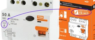
6) Selective RCD from 40A, leakage current 100mA or 300mA
Installation of an incoming panel on a support, standards, rules, tips
First the standards:
According to the PUE (ed. 7), the distance from the floor (ground) to the electric meter terminals should be no more than 1700 mm;
To replace the meter and ensure its safe operation, a switching device or fuses must be installed upstream of the meter. (PUE 1.5.36). By the way, in the same paragraph it is stated that the distance from the switching device to the meter should be no more than 10 meters. That is, if the distance from the support to the house is less than 10 meters, it is possible to install an input panel on the support, and a meter on the facade of the house or in the house.
Important! Let me draw your attention to the fact that they do not circuit breakers (circuit breakers) before the meter, but a switch or fuses.
Electrical panel grounding
Very often the question arises about how to ground an electrical panel. In this case, first of all, it is also necessary to be guided by the requirements of the supplying organization.
If there are no requirements, it is necessary to ground the panel taking into account the grounding system of the electrical network. Most consumer networks have a TN-C grounding system, which involves combining the neutral and protective conductors into a PEN conductor along the entire length of the line. The point of separation of this conductor into protective grounding and neutral conductors is carried out in the shield up to the electric meter, and after separation the grounding system is called TN-CS. According to the rules, the PEN conductor has several repeated groundings on supports along the entire length of the line and at the end, in the metering panel itself on a support (pole), it is also grounded.
The PEN conductor is connected to the metal body of the electrical panel, and the panel, in turn, is connected to a pre-installed grounding conductor (grounding circuit) using a grounding conductor. The cross-section of the grounding wire must be no less than the cross-section of the input power cable.
But it is important to consider that grounding home wiring and the PEN conductor in particular can be not only useless, but also dangerous. If the supply line is in unsatisfactory technical condition, and the repeated grounding of the PEN conductor on the supports (poles) of the line does not meet the requirements, then in the event of a rupture of the PEN conductor, a dangerous potential may appear on the body of the grounded switchboard. In this case, an equalizing current will flow through the grounding conductor and the grounding loop, which can lead to damage to the input cable.
Consequently, if the grounding of the supply line does not meet the requirements for the declared grounding system of the electrical network, then it is better to use the combined PEN conductor of the input cable exclusively as the neutral input wire. In this case, you can implement a CT grounding system with your own hands, that is, install an individual grounding circuit of the wiring and ground the metal body of the electrical panel to it.
Finally, we recommend watching a video that clearly shows the installed grounded shield on a pole:
That's all the recommendations we wanted to provide you with. We hope that now you know how to install a metering panel on a support in accordance with the PUE and what requirements apply to this type of work. We hope the information provided was useful and interesting for you!
Nuances of grounding a private house
There are several options for arranging a ground loop. The specific method is selected taking into account the type of soil on the site and the characteristics of the house. Regardless of the chosen method, it is recommended to make grounding electrodes from pipes, one of the ends of which is pre-flattened to a point.
On the lower section of each pipe (the length of the section should be about 50 cm), 10-15 holes with a diameter of about 5-7 mm are made randomly.
In hot weather, it is recommended to pour a saline solution inside the grounding pipes. To prepare it, just dissolve half a pack of salt in a bucket of clean water. This solution will help maintain resistance at a normal level.
The grounding bars also remain the same regardless of the method chosen. You should refrain from using galvanized steel to create metal bonds - the material will very quickly lose its performance properties.
First step.
Calculate the contour. To do this, you need to find out the soil resistance value in your area. Find out this information in the relevant reference literature or local services. The same service can give you recommended circuit parameters. This will save you from unnecessary hassle, because the calculation formulas are quite complex and voluminous.
Second step.
Choose a suitable location for the circuit. Install the circuit in some place that is rarely visited, the minimum distance from the foundation of the building is 100 cm.
Third step.
Prepare the electrodes. They can be made from steel angles. The minimum width of the product is 5 cm, the optimal length is 250-300 cm.
Fourth step.
Dig a square or triangular hole about 100 cm deep. The electrodes will be placed in the corners of the pit. Therefore, select the depth and width of the pit so that the distance between the installed electrodes is equal to the length of these products.
Fifth step.
Drive the prepared electrodes into the corners of the dug hole. A sledgehammer will help you with this.
Sixth step.
Weld a strip of metal to the electrode pins. The welded connection must be reliable and of high quality. Be sure to treat the welding areas with an anti-corrosion compound, for example, bitumen mastic.
Seventh step
. Pull the metal strip to the input shield. Next, you will need to connect a ground bus to the strip.
If it is not possible to use a full bus, connect a high-quality copper wire to the metal strip. The cross-section of this wire must be at least 10 mm2. Use a bolt and nut to secure the wire. Treat the connection point between the metal strip and the copper wire with an anti-corrosion agent.
Eighth step.
Fill the hole. Firmly compact the backfilled soil.
Now recommendations from energy companies
As you understand, energy companies that sell electricity are only interested in one thing, so that their electricity is not stolen, hence the recommendations.
- The electricity metering unit must be installed outdoors, on the facade of the house or on a special stand, including a support;
- The metering unit cabinet must be locked;
- The metering cabinet and rack must be re-grounded;
- The neutral wire is also re-grounded;
- A circuit breaker must be installed in the metering cabinet, after the meter, to protect the supply line;
And now the very desirable advice from energy companies:
- The cabinet should contain an electronic electricity meter with a pulse output and a controller that automatically transmits data to the transformer substation.
- In addition, the cabinet locking device must have a reed switch relay, which also transmits data when this metering cabinet is opened. This is what I described, the desire of all selling companies and regulatory authorities to install an ASKUE system (automatic electricity metering control system) everywhere.
Installation of ASKUE system in a cottage village
Basic mistakes when installing an electrical panel
If there is no switching device at the input of the switchboard, then there will be no way to de-energize the system to perform the necessary preventive or repair work. Also, they often install non-selective RCDs or do not provide differential protection for all consumers, which ultimately negatively affects safety. To prevent electric shock to a person in the event of an emergency, you will need to install differential protection with a leakage current sensitivity of no more than 30 mA.
In addition, it is necessary to completely insulate the contacts and current-carrying wires. A common violation is the incorrect choice of the shield body itself. It must be of high quality, with a body painted with corrosion-resistant paint, with internal partitions installed without distortions.
Errors include poor-quality installation. As a rule, such violations arise due to the fact that the project was not carried out - there are no working drawings or load calculations. And this is a mandatory stage in such work. Qualified specialists perform electrical installation according to the finished project. In this case, the norms prescribed in the Decree of the Government of the Russian Federation of December 27, 2004 N 861 “On approval of the Rules of non-discriminatory access...” are always taken into account. According to these rules, three phases of 15 kW are standardly connected.
Also, do not forget that installing an input circuit breaker on a switchboard does not replace installing the same device in the house. The machines perform the task of reliable switching devices for quickly turning on/off the entire network.
A qualified electrician will calculate the cost of the complete panel, taking into account all installed devices of the required power.
In the previous article, I talked about the pitfalls that you may encounter when obtaining technical specifications for connecting electricity. One of the points conditions reads: “install the receiving device, including metering devices and protection devices that provide control of the maximum power value.” In simple terms, you need to hang a metal box on a pole in which the meter and other necessary equipment will be placed. In this article we will talk about how to make an electricity metering board yourself and what kind of electricity metering board diagram it is.
conclusions
- If there is a desire and a strong recommendation from the selling organization to “install a meter outside the house,” it is placed in the input device cabinet and taken out of the site.
- The input device cabinet is re-grounded.
- A switching device or fuses are installed before the metering meter.
- After the metering meter, circuit breakers are installed, which are called input circuit breakers;
- As additional protection, SPDs are installed in the water shield installed on the support;
- The VU cabinet with a metering unit must have a window for reading meter readings, and the cabinet door must be locked and sealed.
Sources
- https://RozetkaOnline.ru/podkljuchenie-i-ustanovka/item/219-sborka-shchita-ucheta-380v-s-protivopozharnym-uzo-dlya-chastnogo-doma-sistema-zazemleniya-tn-cs
- https://samelectrik.ru/kak-ustanovit-shhit-ucheta-na-opore.html
- https://profelektrika.ru/uslugi/montazh-avtomatiki/na-stolbakh.html
- https://sovet-ingenera.com/elektrika/schetchiki/ulichnyj-yashhik-dlya-elektroschetchika.html
- https://Proekt-sam.ru/proektsistem/ustanovka-sshetchika-elektroenergii-na-stolb-lep.html
- https://electric-stupino.ru/%D1%83%D1%81%D1%82%D0%B0%D0%BD%D0%BE%D0%B2%D0%BA%D0%B0-%D1% 81%D1%87%D0%B5%D1%82%D1%87%D0%B8%D0%BA%D0%B0-%D0%BD%D0%B0-%D1%81%D1%82%D0% BE%D0%BB%D0%B1%D0%B5/
- https://ehto.ru/elektrika-chastnogo-doma/elektrika-derevyannogo-doma/ustanovka-vvodnogo-shhita-na-opore
[collapse]
How it works in practice
On practice:
- Installation of an introductory shield on a support; in civilized settlements they can withstand up to 1700 mm. The installation height in sparsely populated villages is raised to 2500 mm.
- To lower the cable to the switchboard and lift it back for air entry into the house, do not use SIP wires, but use VVG cable. The cable itself is firmly fixed to the support, hiding it in protective pipes. When entering the house underground, the VVG cable is lowered in pipes to the shield, and after the shield, with the VVbShv cable in the pipe, they go into the trench.
- In the input device, in addition to installing an input switch (before the meter) and circuit breakers (after it), it is necessary to install surge protection devices (SPDs).
Is it possible to bypass
The theft of electricity causes damage to both the citizen and the state. Lovers of “freebies” hack into panels, install gadgets to stop the count, and are included in the circuit without permission. Attempts to cheat the meter lead to fires, power surges, and damage to household appliances.
The government has introduced amendments to the Code of Administrative Offenses of the Russian Federation. From 2021, a triple fine will be issued for repeated illegal tappings. For the first violation you will have to pay 10-15 thousand rubles. For a repeat – from 15 to 30 thousand rubles. A relapse is fraught with removal from office for 2-3 years. For legal entities the measures are stricter. Failure to pay fines may result in exclusion, a ban on traveling abroad, seizure of property, or court action.
The authorities hope that innovations will stop the mass outrages in the electricity sector. Thanks to smart mechanisms, conscientious subscribers will not have to pay the bills of offenders. Responsibility will fall on the debtors. New models will help resolve disputes between suppliers and consumers.
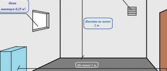
Electrical wiring in the attic
2.1.69. The following types of electrical wiring can be used in attics:
- open;
- wires and cables laid in pipes, as well as protected wires and cables in sheaths made of fireproof or fire-resistant materials - at any height;
- unprotected insulated single-core wires on rollers or insulators (in attics of industrial buildings - only on insulators) - at a height of at least 2.5 m; when the height of the wires is less than 2.5 m, they must be protected from touch and mechanical damage;
- hidden: in walls and ceilings made of fireproof materials - at any height.
2.1.70. Open electrical wiring in the attic must be carried out using wires and cables with copper conductors.
Wires and cables with aluminum conductors are allowed in the attic of: buildings with fireproof floors - when laid openly in steel pipes or hidden in fireproof walls and ceilings; industrial buildings for agricultural purposes with combustible floors - when they are laid openly in steel pipes, excluding the penetration of dust into the pipes and connecting (branch) boxes; In this case, threaded connections must be used.
2.1.71. The connection and branching of copper or aluminum conductors of wires and cables in the attic must be carried out in metal junction (branch) boxes by welding, crimping or using clamps corresponding to the material, cross-section and number of conductors.
2.1.72. Electrical wiring in the attic, made using steel pipes, must also meet the requirements given in 2.1.63-2.1.65.
2.1.73. Branches from lines laid in attics to electrical receivers installed outside attics are allowed provided that the lines and branches are laid openly in steel pipes or hidden in fireproof walls (floors).
2.1.74. Switching devices in circuits of lamps and other electrical receivers installed directly in attic spaces must be installed outside these rooms.