What is a thermocouple?
A thermocouple is a sensor that converts a change in temperature into an electrical signal. Subsequently, the electrical energy from such a sensor is involved in the operation of electronics and automation of stoves, gas boilers and water heaters. When the electrical potential at the ends of the thermocouple changes within certain limits, the gas control is blocked and combustion in the gas stove stops. Such a device allows you to both maintain the gas supply to the burner flame and interrupt its supply in emergency situations.
Physically, a thermocouple is an electrical contact between two conductors made of different materials. Such contact can be provided through:
- Soldering – provides good contact for low-melting materials;
- Welding - provides the most accurate measurements, but also the most energy-intensive process in the manufacture of contacts, well suited for refractory materials;
- Crimping is the simplest method, but provides rather low accuracy, since thermal expansion and contraction disrupts the contact density.
Depending on the operating parameters of geysers or stoves, appropriate methods of connecting conductors are used. It should be noted that the thermocouple of the plate is the contact itself, while all other components (wires, screen, leads, etc.) represent a thermometer.
Comments
I especially liked “try to revive your gas control or “kill” it completely by turning the stove into a USSR device that works just fine without gas control”
- Login to reply
Either no one is reading this, or one of two things. Interesting article. It's a pity, it's hard to read... The font is small and blurry. And in the pictures the text (in the explanatory frames) is completely unreadable. Apparently the material was ripped off from somewhere and copied poorly. I'd like to see the original.
- Login to reply
reset your @ . I'll send it to you by email. article. if there is the same effect, I will correct it, I am the “aftar” of this creation. I don't do plagiarism. ). poked around personally..
- Login to reply
It is not clear why the quality was lost. The original Word document looks flawless.
- Login to reply
- Login to reply
Good afternoon. I wanted to get an opinion or get advice from experts. The valve “stopped” working: I checked the thermocouple separately - it produces 40 mV from a regular burner; I checked the valve - it works exactly starting from 700 mV (dead AAA battery). I don’t understand what the problem is yet, because... It seems like the emf of the thermocouple is within normal limits (I’m very surprised by the reading of your thermocouple. Maybe there’s a problem there.). Because the valve operates from external power, I wanted to know whether the winding on the valve will not be covered when used in this way?
- Login to reply
Good afternoon, I don’t know the indicators of the thermocouple, because... it failed, but the valve was triggered somewhere around 1V, “pulled” 400mA. My entire “kitchen” in the post, when powered by an external power supply, is relevant as a temporary solution to the problem during the period of purchasing (purchasing) a valve or thermocouple, or a kit in general. If you don’t think about buying them, unscrew the valve, remove the rubber gasket, remove the spring - the headache will disappear. ) The stove will turn into the USSR - a device. )Good luck.
- Login to reply
PS. Try repairing the contact connections by removing the thermocouple, cleaning the seat, etc. connections between the terminal and the housing. It seems to me that your thermocouple is bad. Don’t worry about the valve winding. Increase the voltage until the valve operates - it will not take extra current.
- Login to reply
Thank you for such a quick response! I have already cleaned the thermocouple contacts as much as possible, but, alas, or fortunately, there was nothing to clean there except carbon deposits. I have already taken measurements on a test bench without unnecessary details. Considering the gluttony of the valve, it also seems to me that the problem is in the thermocouple, but in contrast to this there is a table of TEDS of standard thermocouples (https://kipiya.ru/2008/04/04/tablica-termo-eds-standartnyx-termopar/, https:/ /temperatures.ru/pages/graduirovochnye_tablicy), where the maximum readings do not exceed 70 mV. That is why I began to look for help, because at the moment I have two impressions: the valve winding has deteriorated since it requires so much to hold and the thermocouple has deteriorated since it produces so little. But neither of these stand up to criticism. Or am I missing something. In general, there are two options left: either remove the valve or buy a kit. For now, I’ll just bypass the thermocouple using external power.
- Login to reply
in terms of standards - the table focuses on industrial thermocouples, low-current (USSR-CIS standards), as for gas control - these thermocouples are “tailored” for bourgeois stoves. In fact, industrial thermocouples produce a LOW-CURRENT SIGNAL to electronic devices (with further amplification thereof) for control thermal processes. As for the t/p gas control, it (it was specially developed for the valve) produces a significant current to the valve, and the valve needs to overcome the resistance of the spring and also press down the gasket. In production there are hardening transformers (soldering of cutters). They produce 2 volts from the step-down winding between the contacts. The cutter is clamped and heated. The current is 400 - 600A. Approximately the gas control thermocouple is rated for a current of up to 500mA. Gas control cuts off the gas from the oven faucets, burners... It won’t go anywhere else until you open the faucet. If you look at the comments on the Internet about gas control, you can conclude that it is not perfect and is short-lived. = flush cistern with electronics unit. ) They install it to “make money” (IMHO). and there are no spare parts. There is a place for do-it-yourselfers to practice.
Principle of operation
The principle of operation of a thermocouple is that any metal has a certain level of electrical charge. Its level is on the order of several microvolts; this value determines the ability of metal electrons to perform directional movement in a closed electrical circuit. When two metals with different potential levels are connected, at the point of contact a transition of electrons occurs from a zone with a higher potential to a zone with a lower one.
In the cold state, a small voltage is obtained at the output, but as the temperature of these materials increases, on the one hand, the potential difference also increases, and accordingly, the value of the EMF generated by the thermocouple increases. In physics, this phenomenon is called the Seebeck effect, named after the scientist who discovered the process. An example of thermopower generation is shown in Figure 1:
Rice. 1: Thermocouple working principle
In practice, materials with thermopower of different directions are used for connection. For example, in a thermocouple made of alumel and chromel, the potential value changes by - 17.3 μV and + 24 μV, respectively, when the temperature changes by one degree Celsius. Thus, when this connection is heated to 300ºC, a voltage of 24 mV will appear at the output.
If we consider the operating diagram (Fig. 2), its circuit includes three elements: a thermocouple, a thermal relay and a solenoid valve. The thermocouple is specially located near the combustion source in order to instantly respond to the main processes in the ovens.
Rice. 2: Operation diagram
Look at the figure; when the thermocouple contact is heated, an EMF arises in it, which causes electric current to flow through the thermal relay circuit to the electromagnet coil. When the gas is ignited by electric ignition, one end of the thermocouple in the oven is heated, and due to the effect described above, an EMF occurs in the circuit. When the thermal relay contacts are closed, electric current flows from the thermocouple through the closed thermal relay contacts along the solenoid valve coil. When the thermocouple is heated, the current in the coil becomes sufficient to move and hold the coil core, which opens the gas supply valve.
If the oven heats up to the value you set, the thermostat is triggered and breaks its contacts in the circuit. Because of this, the coil loses excitation and the magnetic flux no longer holds the core, which returns to its original position and closes the gas control valve. If there is no gas supply, the flame in the stove goes out.
If an emergency occurs when there is a gas leak in the system or an interruption in which the supply stops, and after some interval it resumes again, the gas control system is activated. As soon as the gas in the stove goes out, it quickly cools down, which is why both the EMF and the current in the valve solenoid circuit decrease. The valve closes completely and even when the gas supply to the oven is restored, the valve prevents gas from entering the oven.
Thus, the thermocouple performs the gas control function both in normal situations and in emergency situations.
Why do you need gas automation?
Old-style boilers were manufactured in accordance with the gas parameters and heating system features that were in use several decades ago. These are, for example, models KChM, AOGV. At the same time, their durability allows them to be used for many years to come. But the problem with automation is that quite often it breaks down. In such a situation, there are three options:
- diagnose existing automation and replace the necessary parts;
- equip a reliable and high-quality unit with a modern automatic system;
- buy a new boiler.
The difference, of course, is in the price of the issue, the effort and time of the owner.
Let's consider the cheapest option - troubleshooting gas automation on an old boiler. However, first, let’s figure out why an automatic system is provided in the coolant in general.
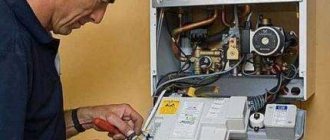
Gas automation allows you to regulate and maintain the required level of coolant temperature, and also serves to automatically stop the gas supply in an emergency situation. Installing automation on an old gas boiler will allow you to be sure that if the burner flame goes out, then after a short time the system will work to stop the gas supply without your participation.
If you want to change the automation, keep in mind that domestic manufacturers produce models that are suitable for almost any old coolant. Imported automation cannot be installed on everything. In addition, when installing foreign automation on old-style gas boilers, not all of its functions may work - the design features of the boiler will not allow it.
Device and design
Rice.
3: example of thermocouple design Structurally, a thermocouple can be divided into the following elements:
- Thermocouple junction - consists of two conductors, less often semiconductors, connected in one circuit;
- Insulated metals - continue the output of working conductors from the point of soldering to the point of connection to the electrical circuit, the wires are insulated from each other along the entire length;
- The shielding coating is made in the form of a metal tube along the entire length of the temperature sensor and its connection wires.
A junction consists of two wires made of dissimilar materials. Which may include non-ferrous and noble metals, usually in alloys. Depending on the composition of the conductors, thermocouples are divided into several types, the features of which are given in the table.
Table 1. Thermocouple types
| Thermocouple type | Alloy | Russian markings | Temperature range, °C | Features of Thermocouple |
| K | chromel-alumel | TXA | from -200 °C to +1000 °C | Ability to work in a neutral atmosphere or an atmosphere with excess oxygen |
| L | chromel-copel | TXK | from -200 °C to +800 °C | The highest sensitivity of all industrial thermocouples. It is characterized only by high thermoelectric stability at temperatures up to 600 °C. |
| E | chromel-constantan | TXKn | from -40 °C to +900 °C | High sensitivity. |
| T | copper-constantan | TMKn | from -250 °C to +300 °C | Can operate in atmospheres with slight excess or deficiency of oxygen. Not sensitive to high humidity. |
| J | iron-constantan | TZHK | from -100 °C to +1200 °C | Works well in rarefied atmospheres. The low cost is due to the iron included in the composition. |
| A | tungsten-rhenium | TVR | above +1800 °C | Good mechanical properties at high temperatures. Can operate under frequent and sudden heat changes and under heavy loads. They are unpretentious in manufacturing and installation, as they are slightly sensitive to dirt. |
| N | nikhrosil-nisil | TNN | from -200 °C to +1300 °C | In the group of base metals it is considered the most accurate thermocouple. High stability at temperatures from 200 to 500 °C. |
| B | platinumrhodium-platinumrhodium | TPR | from +100 °С to +1800 °С | High mechanical strength. Greater stability at high temperatures. Slight tendency to grain growth and embrittlement. Low sensitivity to pollution. |
| S | platinum-rhodium-platinum | TPP10 | from 0 °C to +1700 °C | High measurement accuracy. Good reproducibility and stability of thermoEMF. |
| R | platinum-platinum | Chamber of Commerce and Industry14 | from 0 °C to +1700 °C | Has properties identical to type S thermocouple. |
As you can see from the table, different types determine different operating temperature ranges, sensitivity to temperature changes, stability under long-term load and other characteristics. What should be taken into account when choosing a specific model for the stove in case of replacement or installation from scratch.
Depending on the operating temperature, the appropriate material is selected for insulating the twisted strands of thermocouple conductors. For example, any type can be used up to 120ºС, porcelain up to 1300ºС. There are models above 1300 ºС, in which magnesium, beryllium and aluminum oxides are used for insulation, but due to the fact that such temperatures are not available in household appliances, it is not advisable to purchase and consider such thermocouples.
Check, clean, replace
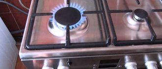
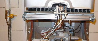
If the stove starts to light up poorly, it is likely that the thermocouple is clogged or faulty. But it is worth noting that the cause of the malfunction may not affect this element. To check, follow these steps: turn the oven knob and light the gas. If, after you release the knob, the oven goes out, this is the first sign that the gas control system does not open the gas supply valve in the stove.
Most likely, the surface of the measuring element is clogged and it does not perceive temperature changes in the environment. To repair gas equipment in stoves from Hephaestus, Ariston, Indesit, Gorenje, etc. You should first clean the thermocouple in the stove, to do this:
- First close the gas taps and disconnect the stove from the external power supply;
Rice. 4: turn off the gas supply to the oven - Open the oven and remove everything unnecessary from it - you should be able to get inside freely, if something bothers you, remove it, if necessary, you can remove the door from the stove;
Rice. 5: Remove any excess from the oven - Find the thermocouple itself - as a rule, it is located in the upper part of the oven; it must be installed near the flame divider;
Rice. 6: thermocouple in the oven - If carbon deposits, soot and other debris are found on its surface, they should be cleaned using fine sandpaper; cleaning with impact is strictly prohibited, as you can damage the thermocouple irrevocably;
- Collect the deleted garbage and test the functionality.
If such a gas control repair does not bring the desired result, you should check the thermocouple using a multimeter or millivoltmeter. To do this, you will need to get to the place where the thermocouple is connected to the electrical network of the stove. As a rule, it is located under the front panel or top cover, where the temperature switch or gas valve is located. The contacts could also come loose here, then it’s easy enough to fix them; if not, proceed to measurements.
Set the multimeter's measurement limit to around tens of millivolts. Connect the probes to the thermocouple terminals and heat the measuring element (not necessarily with open fire, but this is a fairly affordable method).
Rice. 7: checking the thermocouple with a multimeter
If the millivoltmeter shows a change in voltage at the terminals, the device is working properly and the reason is something else. Otherwise, you may have incorrectly set the limit for your thermocouple model or the automatic gas control system may be faulty.
Replacing a gas stove thermocouple
In most cases, failure is characterized by burnout of conductors. Soldering them yourself or welding them at home is possible, but impractical, since after splicing it is impossible to ensure the same measurement accuracy. Therefore, the best option is to replace the thermocouple. For this:
- Purchase a new replacement model on the Internet; it is better to do this using the thermocouple code, which can be found on the device itself or in the passport of the gas stove;
- Also disconnect the stove from the electrical network and gas supply system;
- Remove the front panel and top cover of the cooker and disconnect the electrical leads where they connect to the solenoid valve;
Rice. 8: Remove the front panel or top cover - Unscrew the fastening nut in the oven and remove the thermocouple; if the fastening element does not give in immediately, do not use excessive force so as not to break the fastening point, use WD-40 or any other solvent;
Rice. 9: Unscrew the thermocouple - Install a new thermocouple in the hole and secure it in the same way as the previous one, connect it to the internal electrical wiring circuit of the stove;
Rice. 10: Install a new thermocouple - Reassemble in reverse order and test the operation of the gas stove.
How to clean an AOGV boiler
For this operation you will need a regular plastic bottle cleaning brush. It can be purchased at a hardware store and is perfect for cleaning vertical channels. Tie it with electrical tape to a wooden stick so that you can easily go through the channels along their entire height. In order not to spread excess dirt in the boiler room, take everything that can be moved out into the yard for cleaning.
- Start cleaning from the top plane of the heat exchanger, clean off and sweep down all the soot.
- Then comes the turn of cleaning the channels. The soot will come off the walls quite easily if it has not yet hardened, otherwise you will have to make some effort.
- After completing the cleaning process of the boiler itself, proceed to the removed components and parts. Clean the top cover of the heat exchanger. After this, remove layers of soot on the top cover of the boiler itself and from the hood.
- Lastly, use a brush to brush away the soot that has accumulated from above from the burner block; the burner itself is already clean.
Immediately lightly clean the tube with fine sandpaper. This completes the process of cleaning the boiler and its parts. Proceed to reassembling the AOGV boiler.
Safety Tips
Due to the fact that the thermocouple is responsible for the safe operation of the gas stove, care should be taken to ensure that optimal conditions are provided during replacement and operation:
- At the first sign of a gas leak, immediately turn off the gas taps and ensure the room is ventilated;
- The direction of the measuring element should be uniformly approaching the flame or located along the heat source;
- The wire should not experience mechanical load or tension, but it should not dangle freely either;
- When replacing one model with another, choose the one that is suitable in terms of parameters and temperature conditions for your stove.
If you are unable to complete this procedure on your own or if you smell gas after replacement, immediately contact your gas service to prevent an emergency.
Measurement speed
The performance is determined by the ability of the primary converter to quickly respond to temperature surges and the subsequent flow of input signals from the measuring device.
Factors that increase performance:
- Correct installation and calculation of the length of the primary converter;
- When using a converter with a protective sleeve, it is necessary to reduce the mass of the assembly by selecting a smaller diameter of the sleeves;
- Minimizing the air gap between the primary converter and the protective sleeve;
- Using a spring-loaded primary converter and filling the voids in the sleeve with a heat-conducting filler;
- A fast moving or denser medium (liquid).