The supply of electricity to the house is handled by the relevant organization. This type of work is associated with certain risks (all operations are carried out without removing the voltage), so electrical safety rules must be strictly observed. The choice of cable for introducing electricity into a private house (section, number of cores, material) lies entirely on the shoulders of the owner of the site. The durability of the electrical network in the house directly depends on this choice, so you should approach the work very seriously.
Cable entry can be carried out by air - from the pole to the house. But they also resort to introducing the cable into the house through the foundation, underground.
Subscriber branch: concept, principle of operation
On each street there are main power lines, the voltage through which comes from the nearest transformer substation. A higher potential difference of 6 or 10 kV arrives at the transformer. But this information is solely for general development, since the main line voltage is 380 V, and between the phase and the neutral wire - 220 V.
To lay a cable from a pole to a separate consumer - a private house, it is necessary to install a subscriber branch from the main line. A subscriber branch is the supply of electricity to an individual consumer. With this procedure, you must correctly calculate the wire through which the electricity will be supplied.
Electrical Safety Protective Measures
If you strictly follow all the rules during operation, the use of electrical appliances does not pose any danger. Protection against electric shock is achieved in the following ways:
- the part of the electrical circuit through which the current passes must not be accessible to accidental touch;
- live parts that are open must not contain voltage dangerous to human life, even if the insulation is broken;
- such inaccessibility is achieved through protective shutdown, the use of low voltage, double insulation, equalization and potential equalization, the implementation of barriers, and the location of electrical equipment outside the accessibility zone.
The use of measures in combination to protect against electric shock should not reduce the effectiveness of each.
If the electrical equipment is located in the potential equalization area, and the highest operating voltage is no higher than 25V AC and no more than 60V DC, then there is no need for protection against direct contact.
Also, the protective functions of electrical equipment must be provided during the manufacture of the latter, or during installation.
How cable tension is done
After fixing the conductor on special rollers, begin to tension it. This requires the following tool:
- hand winch;
- stretching device;
- dynamometer.
The hand winch is attached to the nearest support using anchor bolts, and the cable is pulled along it using a tensioning device. The tension force is regulated by technical documentation and is controlled using a dynamometer.
Subscriber branch cable cross-section
The regulated procedure for laying conductors through the air is specified in the rules for electrical installations. The requirements of the rules are established for power lines with voltages up to 1000 V.
Calculations of the cable cross-section should be based on the operating mode: normal, emergency or installation. Since the branch is standard, you should select the normal (nominal) mode. The PUE provides for the minimum permissible wire cross-section:
- It is allowed to use a wire made of a standard aluminum alloy (not heat-treated) with a cross-section of at least 25 mm².
- When using a conductor made from a combination of steel and aluminum (heat-treated), its cross-section should also be 25 mm².
- If a copper wire is laid, its cross-section can be 16 mm².
The above indicators are suitable for standard ice wall thicknesses of no more than 10 mm. If the thickness reaches 15 mm and above, then the cross-section of the aluminum and steel-aluminum cable remains unchanged, and the copper conductor must be increased to 25 mm².
Information is presented in Chapter 2.4 of the PUE.
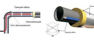
Rules for grounding pipelines
Grounding of pipelines is a mandatory measure, enshrined in the PUE. This is how you can increase the safety of their operation, because static electricity accumulates in pipe systems, plus there is always the possibility of lightning striking the pipes. The requirements of the rules for the construction of electrical installations are to provide grounding not only for external pipelines, but also for internal ones (technological and communication).
The PUE clearly regulates how pipelines should be grounded.
- Firstly, the pipe system must be a single continuous network connected into a single circuit.
- Secondly, pipelines must be connected to the grounding system at at least two points.
As for the first position, this does not mean that the pipeline system itself must be continuous. Here it will be enough to ensure the connection of sections or individual pipelines into one single network, for which so-called wafer jumpers are most often used. In fact, this is an ordinary copper wire of the brand either PVZ or PuGV. Fastening of jumpers to the pipeline is ensured by welding, bolting, or a grounding clamp for pipes is installed.
As for the second position, experts recommend not to scatter along the entire line of the technological chain, just to make a connection at the beginning and end of the circuit.
The main operating parameters used to calculate the cable
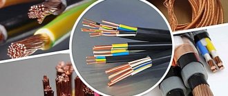
To connect the cable to the house, you need to decide on its cross-section. The cable cross-section is its area at the cut site. Generally accepted standards (according to the PUE) are indicated in the previous section. The main operating parameters by which the cable cross-section is selected are its cross-section and rated current.
But in addition to the cross-section, a certain conductor material is also needed. Nowadays, copper wires are most often used; they have lower resistance, but are more expensive. Aluminum does not have such high conductivity, but its price is lower than that of copper products. It should be remembered that with the same load, the cross-section of the aluminum conductor should be larger than that of copper.
And the last parameter is the number of cores, but with this everything is much simpler. When introducing only one phase and a working zero into the house, a two-core cable is used; when introducing three phases and a zero, a four-core cable is used. In both options, the cross-section of the zero conductor may be smaller than that of the phase conductor.
Cable laid over the air
The main type of installation of the input cable is its installation by air. Air input has its advantages:
- Minimum labor costs.
- It takes a short amount of time to connect your home. It is rare that such work takes more than two hours.
- Low cost of consumables: anchor bolts or clamps, special brackets, insulators.
- Possibility of quick troubleshooting, even if the entire cable needs to be replaced.
The following types of cables are used for aerial installation:
- SIP cable is a self-supporting insulated wire.
- Non-insulated, material - aluminum.
- Bare aluminum with steel core.
How to choose the right section and brand of SIP
So what kind of cable should be used to bring electricity into the house? Many people resort to using SIP cable; it is allowed in many electrical industries and even in high voltage lines up to 35 kW.
This cable has its own design feature - phase wires, most often in the amount of three, wrap around the fourth - zero. Therefore, the appearance of SIP resembles a rope twisted into a spiral. High-quality LDPE or XLPE polyethylene is used to insulate conductors. These types of materials have high resistance and a long service life, which allows them to be used even with sudden temperature changes.
The core, which is located in the middle and has zero potential, is made of aluminum alloy. Sometimes the zero does not have its own insulation, which is required for phase conductors.
The SIP cable has one serious drawback - due to the presence of insulation, the cable is insufficiently cooled, so the current loads allowed are lower than those of uninsulated conductors. When choosing SIP, you should pay attention to insulation:
- With insulation made of thermoplastic polyethylene, temperature loads of up to 70 degrees are allowed. Suitable for this parameter: SIP-1, SIP-1A, SIP-4, SIPn-4.
- When choosing cross-linked polyethylene as an insulating material, temperature loads of up to 90 degrees are allowed. Overload mode indicators and short circuit current parameters also increase. Such performance characteristics have: SIP-2, SIP-2A, SIPs-4, SIP-3, PEV and PEVG.
The SIP cross-section is also determined by power consumption, the formula is presented above.
Signal Wire Shielding Methods
The signal wire (cable) is used to connect various elements (components) of the system. Most often, the signal wire contains several pairs of conductive wires with polyethylene insulation, as well as with a PVC sheath. Some types of signal wires have a special shield to protect against electromagnetic interference and are called “shielded signal cables.”
Shielding Signal Wires
Shielding is the protection of a signal wire from noise or unwanted signals.
Signal wires have high quality signal transmission due to their shielding and twisted pair construction to ensure better matching of their longitudinal impedance and ground impedance. At high frequencies, common-mode interference can occur due to the difference between the length of the wires and the frequency characteristics of their impedances.
Signal wire shielding methods take into account the path of interference.
To completely eliminate the adverse effects of parasitic capacitive coupling, an electrostatic screen made in the form of a conductive tube is used. In this case, it is correct to ground the electrostatic shield only from the side of the signal source. In Fig. Figure 1 shows how to improperly ground an electrostatic shield.
In Fig. Figure 2 shows hybrid grounding, which is the most popular method when transmitting a broadband signal from a distant source with high resistance.
Making a screen that will reliably protect against parasitic inductive couplings is much more difficult than a classic electrostatic screen. For manufacturing, you need a material with increased magnetic permeability. In addition, the thickness of such a screen should significantly exceed the thickness of electrostatic screens.
For frequencies less than 100 kHz, it is possible to use steel screens or screens made of permalloy (an alloy of iron and nickel). For higher frequencies, screens made of copper or aluminum are suitable.
Since shielding the magnetic component of interference is difficult, special attention must be paid to reducing the inductance of the signal cable and selecting suitable receiver and transmitter circuitry. In Fig. 3, 4, 5 and 6 show connection diagrams for the amplifier and screen, providing different rms noise amplitudes.
For most, for example, temperature sensors, the signal sources do not have a protective ground, and therefore an electrostatic shield is used along with a differential amplifier and output resistors. The screen grounding diagram in this case is shown in Fig. 3.
Double shielding of long cable
A double shield (Fig. 7) is used to improve the quality of shielding over a wide frequency spectrum. The internal screen is grounded on one side (the signal source) to prevent the passage of capacitive interference, while the second, external screen, is used to reduce high-frequency interference.
In any case, to prevent accidental contact of the screen with metal objects and the ground, it must be insulated.
In the case of a long cable, even with proper grounding, interference still passes through the screen, and therefore it is better to transmit the signal over a significant distance or with serious requirements for measurement accuracy either in digital form or via a fiber-optic cable. For this purpose, analog input modules with a digital RS-485 interface or fiber-optic converters of the RS-485 interface can be used.
Galvanic isolation
The above problems can be radically solved using galvanic isolation (Fig. with separate grounding of the digital, analog and power parts of the system. That is, the signal between electrical circuits is transmitted without contact between them.
You may also be interested in:
gauss-instruments.ru
Cables for laying in the ground
When choosing a wire for underground input into a house, you should pay attention only to high-quality and reliable products, since a very common problem with such input is a breakdown to the ground.
Modern cables, made specifically for installation in the ground, have the following insulation:
- Pressed paper with special impregnation.
- Polyethylene.
- Polyvinyl chloride.
Very often they use VBBShV or PvBSHV conductors, which in addition to standard insulation have strip armor. AABL cable is also popular, but has a lower cost, since its shell is made of aluminum. Where there are risks of damage, PvKShp with wire mesh is most often used.
Advantages and vulnerabilities of underground electrification
Supplying electricity underground
Introducing an electrical cable into a house underground instead of overhead lines has a number of advantages:
- does not spoil the architecture and design of the site;
- does not experience atmospheric influences;
- high fire safety.
In addition, eyeliner made in this way is protected from theft and vandalism. This is especially important if the building remains unattended for a long time.
Underground installation of electrical cables has some disadvantages:
- may be subject to mechanical stress during the process of swelling and subsidence of the soil;
- the influence of groundwater, soil freezing, pressure from the roots of large trees;
- Insects and rodents can damage the wiring;
- it is susceptible to aging and corrosion.
The durability of electrical wiring depends on the composition of the soil and its saturation with water, thermal fluctuations and vibration processes.
How does electricity enter the house?
When introducing electricity into a private house, use one of the previously presented methods (laying a cable through the air on a cable or in the ground). When supplying electricity to a house, you must strictly follow the basic rule - the input cable should not have transits. The panel in which the consumer circuit will be presented should be located near the input cable for easier installation.
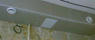
The conductor cannot be installed indoors directly through a hole in the wall. The hole must have additional protection; usually a metal pipe is used for this. The diameter of the pipe should be taken with a reserve, and the free space between the cable and the walls of the pipe should be sealed with cement mortar.
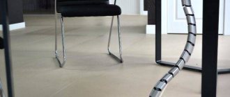
Ways to organize wiring inside the house
There are several options for performing internal wiring.
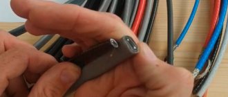
Connecting different cables inside
Welding the wire
The SIP conductor is broken and connected to the VVGng cable by twisting and strengthening by soldering. The technique is not reliable, as it can lead to fires.
Connecting various conductors with fittings
The coupling of SIP and VVGng is carried out using standard reinforcing bars, piercing clamps or other elements near the insertion point. It is unacceptable to use SIP in a residential area - it supports combustion processes.
Through the difavtomat
The connection diagram provides for the use of a two- or four-pole differential circuit breaker. The device is located in a separate sealed box. The cable is laid from the main line to the box and connected to VVGng in a corrugation.
To increase protection, a machine with a rating higher than the distribution board is used. This way, if there is a short circuit or overload, you can restore the line without leaving your home. Another device is installed outside, de-energizing the internal cable and preventing fire.
Electrical lines can be introduced into a residential building by air or underground. Before starting work, it is necessary to obtain permits and select a SIP cable and its cross-section.
How to make the correct air injection
When introducing a cable into a house from a nearby line or pole, you should invite specialists. To attach it to the wall, you must use special overhead brackets (especially when installing it in a wooden house). This will allow you to securely fix it and not damage the insulation. At a certain distance from the wall, a slight deflection of the cable should be made in order to prevent rainwater from entering the room.
The cable on which the cable is attached must not be overtightened on the supports, since during sudden and frequent temperature changes (which occur during cold periods of the year), it can become deformed.
2.3.72
When grounding or grounding the metal sheaths of power cables, the sheath and armor must be connected by flexible copper wire to each other and to the housings of the couplings (end, connecting, etc.). On cables 6 kV and above with aluminum sheaths, grounding of the sheath and armor must be carried out with separate conductors.
It is not required to use grounding or neutral protective conductors with a conductivity greater than the conductivity of the cable sheaths, however, the cross-section in all cases must be at least 6 mm.
The cross-sections of grounding conductors of control cables should be selected in accordance with the requirements of 1.7.76-1.7.78.
If an external end coupling and a set of arresters are installed on the structure support, then the armor, metal shell and coupling must be connected to the grounding device of the arresters. In this case, using only metallic cable sheaths as a grounding device is not allowed.
Overpasses and galleries must be equipped with lightning protection in accordance with RD 34.21.122-87 “Instructions for the installation of lightning protection of buildings and structures” of the USSR Ministry of Energy.
Some examples of input cable protection
The best protection for the input cable is its insulation and the method of laying it in a place where no one can reach it. This can be a method of laying underground or by air. To prevent the harmful effects of natural conditions, the conductor can be laid in a special PVC pipe, but few do this, due to the significant increase in the cost of the structure.
To protect the wire in the wall, it is best to use a metal pipe. A replacement for metal can be PVC, which has a more affordable price.
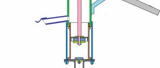
Cable entry underground
A wire laid underground does not require fastening to the wall; in this case, the conductor is laid through the foundation. The part of the cable that comes out of the ground must be protected using a metal tube or a thick PVC conduit.
To lay a cable in the ground, a trench must be made, at least 70 cm deep. At the bottom of the trench, a sand “cushion” is made, 15–20 cm thick. The cable is laid on it and closed with earth on top. Underground cable entry is a labor-intensive process, but more durable than overhead entry.
Comments:
Step
An intelligent article, described in some detail, thanks to the author. But fastening it with tapes to the support every 50 cm is overkill. It is not necessary. According to the PUE, this distance is 100 cm and is sufficient to firmly hold the cable.
Larion
So I counted the current collectors. Can you tell me how much cable power reserve should be taken in order for the whole system to work?
Magomed
Larion, ideally, the more, the better. The more powerful the cable is installed in your home, the less likely it is that it will ever fail. More power means longer service life.
Leave a comment Cancel reply
Related Posts
Methods for gating walls using various tools. Features and some secrets of installing open wiring in a wooden house with your own hands Armored copper cable for your home and site Drawing up a wiring diagram for a one-room apartment, selecting the necessary equipment
How to supply electricity to a distribution panel
When using an ordinary conductor, it is enough to simply connect it to the main circuit breaker, from which the electricity will then go to other consumers. But when using an SIP or an insulated conductor, you should install a switching unit - a separate place for the transition of the input cable to the one that will be routed to the panel.
It is most convenient to use a branch clamp for this - 2 copper plates, fastened to each other with four bolts and placed in a special plastic box.
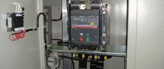
What is an input device cabinet
The input device can be briefly classified as all switching and other power control devices that are installed directly at the main line input. For ease of installation of such devices, special cabinets are used, which have special fastenings.
In the input device cabinets the following can be located:
- circuit breakers;
- switches;
- circuit breakers;
- counters.
- measuring instruments.