Requirements for electrical wiring in residential buildings according to PUE 7
Electrical wiring and cable lines
7.1.32. Internal wiring must be carried out taking into account the following:
- Electrical installations of different organizations, separate administratively and economically, located in the same building, can be connected by branches to a common supply line or fed by separate lines from the ASU or main switchboard.
- It is allowed to connect several risers to one line. On branches to each riser supplying apartments in residential buildings with more than 5 floors, a control device combined with a protection device should be installed.
- In residential buildings, lamps in staircases, lobbies, halls, floor corridors and other indoor premises outside apartments must be powered via independent lines from the ASU or separate group panels powered from the ASU. Connecting these lamps to floor and apartment panels is not allowed.
- For staircases and corridors with natural light, it is recommended to provide automatic control of electric lighting depending on the illumination created by natural light.
- It is recommended to supply electrical installations of non-residential buildings with separate lines.
7.1.33. Supply networks from substations to VU, ASU, main switchboard must be protected from short-circuit currents.
7.1.34. In buildings, cables and wires with copper conductors* should be used.
(* Until 2001, according to the existing construction backlog, the use of wires and cables with aluminum conductors is allowed)
Supply and distribution networks, as a rule, must be made of cables and wires with aluminum conductors if their design cross-section is 16 mm 2 or more.
Power supply to individual electrical receivers related to the engineering equipment of buildings (pumps, fans, heaters, air conditioning units, etc.) can be carried out by wires or cables with aluminum conductors with a cross-section of at least 2.5 mm 2.
In museums, art galleries, and exhibition spaces, it is permitted to use lighting busbar trunking systems with a degree of protection IP20, in which the branch devices to the lamps have detachable contact connections located inside the busbar trunking box at the time of switching, and busbar trunking systems with a degree of protection IP44, in which the branching devices to the lamps are made with using plug connectors that ensure the branch circuit is broken until the plug is removed from the socket.
In these premises, lighting busbars must be powered from distribution points by independent lines.
In residential buildings, the cross-sections of copper conductors must correspond to the calculated values, but not be less than those indicated in Table 7.1.1.
7.1.35. In residential buildings, laying vertical sections of the distribution network inside apartments is not allowed.
It is prohibited to lay wires and cables from the floor panel in a common pipe, common box or channel that supply lines to different apartments.
Fire-retardant installation in a common pipe, common box or channel of building structures made of non-combustible materials, wires and cables of supply lines of apartments together with wires and cables of group lines of working lighting of staircases, floor corridors and other indoor premises is allowed.
Table 7.1.1. The smallest permissible cross-sections of cables and wires of electrical networks in residential buildings
| Line names | Smallest cross-section of cables and wires with copper conductors, mm 2 |
| Group network lines | 1,5 |
| Lines from floor to apartment panels and to the settlement meter | 2,5 |
| Distribution network lines (risers) for supplying apartments | 4 |
7.1.36. In all buildings, group network lines laid from group, floor and apartment switchboards to general lighting fixtures, plug sockets and stationary electrical receivers must be three-wire (phase - L, neutral working - N and neutral protective - PE conductors).
Combining zero working and zero protective conductors of different group lines is not allowed.
The neutral working and neutral protective conductors are not allowed to be connected on panels under a common contact terminal.
Conductor cross-sections must meet the requirements of clause 7.1.45.
7.1.37. Electrical wiring in the premises should be replaced:
hidden - in the channels of building structures, embedded pipes;
open - in electrical skirting boards, boxes, etc.
In technical floors, undergrounds, unheated basements, attics, ventilation chambers, damp and especially damp rooms, it is recommended that electrical wiring be carried out openly.
In buildings with building structures made of non-combustible materials, permanent, monolithic installation of group networks is allowed in the grooves of walls, partitions, ceilings, under plaster, in the floor preparation layer or in the voids of building structures, carried out with cable or insulated wires in a protective sheath. The use of permanently embedded wiring in panels of walls, partitions and ceilings, made during their manufacture at construction industry factories or carried out in the mounting joints of panels during the installation of buildings, is not allowed.
7.1.38. Electrical networks laid behind non-passable suspended ceilings and in partitions are considered as hidden electrical wiring and should be carried out; behind ceilings and in the voids of partitions made of flammable materials in metal pipes with localization capabilities and in closed boxes; behind ceilings and in partitions made of non-combustible materials* - in pipes and ducts made of non-flammable materials, as well as flame retardant cables. In this case, it must be possible to replace wires and cables.
(* Suspended ceilings made of non-combustible materials mean those ceilings that are made of non-combustible materials, while other building structures located above suspended ceilings, including interfloor ceilings, are also made of non-combustible materials)
7.1.39. In rooms for cooking and eating, with the exception of apartment kitchens, open laying of cables is allowed. Open wiring of wires in these rooms is not allowed.
In apartment kitchens, the same types of electrical wiring can be used as in living rooms and corridors.
7.1.40. In saunas, bathrooms, toilets, showers, as a rule, hidden electrical wiring should be used. Open cable routing is allowed.
In saunas, bathrooms, toilets, showers, laying wires with metal sheaths, in metal pipes and metal sleeves is not allowed.
In saunas for zones 3 and 4 according to GOST R 50571.12-96 “Electrical installations of buildings. Part 7. Requirements for special electrical installations. Section 703: Premises Containing Sauna Heaters" electrical wiring with an insulation temperature rating of 170°C must be used.
(Note from the portal buildingclub.ru: more detailed information about electrical wiring in baths and saunas can be found on our portal: Electrical wiring in the bathroom, shower, sauna and bathhouse according to PUE 7
- Preventing clogging. Rules for installing and maintaining grease traps for the kitchen
Types of electrical outlets, how to choose
Back to school: how to arrange a school room for games and learning?
7.1.41. Electrical wiring in attics must be carried out in accordance with the requirements of Section. 2.
7.1.42. Through the basements and technical undergrounds of sections of the building, it is allowed to lay power cables with a voltage of up to 1 kV, supplying electrical receivers of other sections of the building. The specified cables are not considered as transit; laying transit cables through basements and technical undergrounds of buildings is prohibited.
7.1.43. Open laying of transit cables and wires through storerooms and warehouses is not permitted.
7.1.44. The lines supplying refrigeration units of trade and public catering enterprises must be laid from the ASU or main switchboard of these enterprises.
7.1.45. The selection of conductor cross-sections should be carried out in accordance with the requirements of the relevant chapters of the PUE.
(Note from the portal buildingclub.ru: you can find out more about the cross-section of conductors on our portal: requirements for cables according to PUE.
Single-phase two- and three-wire lines, as well as three-phase four- and five-wire lines when supplying single-phase loads, must have a cross-section of zero working (N) conductors equal to the cross-section of phase conductors.
Three-phase four- and five-wire lines when supplying three-phase symmetrical loads must have a cross-section of zero working (N) conductors equal to the cross-section of phase conductors, if the phase conductors have a cross-section of up to 16 mm 2 for copper and 25 mm 2 for aluminum, and for large cross-sections - not less than 50% of the cross-section of phase conductors.
The cross-section of PEN conductors must be at least the cross-section of N conductors and at least 10 mm 2 for copper and 16 mm 2 for aluminum, regardless of the cross-section of the phase conductors.
Note! Which voltage stabilizer for an apartment should I choose?
The cross-section of PE conductors must be equal to the cross-section of phase conductors when the latter cross-section is up to 16 mm 2, 16 mm 2 when the cross-section of phase conductors is from 16 to 35 mm 2 and 50% of the cross-section of phase conductors for large cross-sections.
- Installation of electrical wiring in an apartment in a new building
- Laying electrical wiring in an apartment along the ceiling
- Electrical wiring in the apartment rules and regulations
The cross-section of PE conductors not included in the cable must be at least 2.5 mm 2 - in the presence of mechanical protection and 4 mm 2 - in its absence.
Which wire is better to choose for wiring in a private house?
Taking into account modern loads on the electrical network due to the inclusion of powerful household appliances, it is recommended to use a multi-core copper cable when installing or replacing wiring.
For sockets, VVG 3x2.5 is most often used. Even when all household devices are turned on simultaneously, it can withstand a load of 27 A with a power of 5.9 kW.
Lighting requires less energy consumption, so electric current is supplied to the switches using VVG 3x1.5.
A wooden house must have an increased level of fire safety. According to the rules of the PUE, in this case the cable is laid in metal pipes. It is unacceptable to use a plastic box.
Section diameter is an indicator of cable power
Physical laws say that the maximum amount of current that this conductor can conduct through itself without heating depends on the cross-sectional diameter of the conductor. If you try to conduct a current more than the limit figure, this will lead to heating of the conductor, and the greater the current and the duration of the “session”, the higher the temperature.
For a residential subscriber, the above is interpreted as follows.
The diameter of the cable cross-section means the maximum permissible number of kilowatts (kW) that can be consumed in the apartment. That is, which and how many electrical appliances can operate simultaneously. The larger the diameter, the more devices can be used simultaneously without any fear for life and health. Theoretically, it is possible to “hang” more power on the cable than its diameter allows. But in this case, heating of the current-carrying conductor, damage to the insulation, followed by the effects of burnout, combustion... ignition, is inevitable.
Therefore, the choice of the cross-section of the input cable must be approached with all seriousness: after all, both the safety and ease of use of household electrical appliances depend on it.
Step-by-step instructions on how to connect a single-core wire
After you have purchased the RCD and all the necessary devices for installation, you can begin to work. It must be remembered that all stages of installation must be carried out sequentially and all safety measures must be taken.
Practical advice
Experienced electricians recommend installation in the following sequence:
- de-energize the shield. Check the presence of current using the indicator;
- care must be taken to ensure that no one unexpectedly turns on the electricity;
- the equipment must be firmly snapped onto the DIN rail;
- Electricians recommend connecting the device according to this principle - all incoming wires are at the top, and outgoing wires are at the bottom. This generally accepted scheme will help avoid confusion when replacing equipment;
- there should be no kinks in the wiring when connecting;
- disconnect excess parts of the cable with wire cutters;
- Carefully remove the insulation from the cable by 10 mm;
- Install the cable into the required terminals and secure it. It is necessary to monitor the clamping force - tightly twisted terminals will quickly lead to breakage of the switch;
- turn on the power supply;
- check the voltage access to the switch using an indicator.
Common Mistakes
Sometimes it happens that the power switch does not perform its functions, so you have to reinstall it again. To avoid malfunctions, you need to avoid the following installation errors:
- the insulation from the wire has come into contact. If the insulation is not removed before installation, this increases the risk of a short circuit that leads to a fire;
- connecting several wires with different cross-sections to one terminal. In this case, only a large cross-section core is tightened well, and thin wires have poor contact, which leads to melting of the housing and a fire. This happens when connecting various devices to the switch. To avoid this, you need to use jumpers between cables and devices. They are made from wires of the same cross-section;
- Do not connect copper and aluminum wires together. The device will become unusable due to the oxidation process when two metals are combined;
- You should not connect a straight wire to the terminal, but you need to bend it with a hook, which will increase the contact area and increase the performance of the device; such a cable is also more difficult to pull out of the device.
Section calculation algorithm
There is a proven diagram for calculating the cross-section of the input cable, which is used in design. It is based on the postulate that the cross-sectional diameter of the input cable is selected depending on the expected power of all devices operating in the apartment.
Stage 1: Inventory
At the first stage, a list of electrical appliances that are present in the apartment is compiled. It is assumed what equipment will be purchased in the future and the list is expanded. Assumptions, of course, are best made with a reasonable margin for the long-term future. Each device is assigned an approximate power consumption.
You can use a table that roughly shows a list of typical household electrical appliances and their approximate power consumption.
- Installation of electrical wiring in a one-room apartment
- Program for installing electrical wiring in an apartment
- Which voltage stabilizer for an apartment should I choose?
| Name of electrical appliance | Approximate power, W | Name of electrical appliance | Approximate power, W |
| TV | 300 | air conditioner | 1500 |
| Printer | 500 | instantaneous water heater | 5000 |
| computer | 500 | boiler | 1500 |
| hair dryer | 1200 | drill | 800 |
| iron | 1700 | hammer drill | 1200 |
| electric kettle | 1200 | electric sharpener | 900 |
| fans | 1000 | Circular Saw | 1300 |
| toaster | 800 | electric planer | 900 |
| coffee maker | 1000 | jigsaw | 700 |
| vacuum cleaner | 1600 | Grinder | 1700 |
| heater | 1500 | a circular saw | 2000 |
| Microwave | 1400 | compressor | 2000 |
| oven | 2000 | lawn mower | 1500 |
| electric stove | 3000 | electric welding machine | 2300 |
| fridge | 600 | water pump | 1000 |
| washing machine | 2500 | electric motors | 1500 |
| lighting | 2000 |
Stage 2: Simple Arithmetic
Next, the total cardinality of our list is calculated. The approximate power required for lighting is added, depending on the size of the apartment, the expected lighting intensity, and the expected type of lighting fixtures.
The resulting figure is an estimate of the power consumption in the apartment for the case if all devices are turned on at the same time. However, such a situation is very unlikely, and therefore in electrical engineering it is generally accepted that a maximum of 75% of the available equipment is turned on at the same time. And the resulting total power is multiplied by a factor of 0.75, and the resulting figure is taken as the basis for calculating the cross-section of the input cable.
Stage 3: Logic and Physics
Currently, electrical cable cores are made of copper and aluminum. There are formula relations that connect the maximum permissible current (and, accordingly, power) for a copper cable with the diameter of its cross-section. For standard copper cable sizes, there are calculated current and maximum power ratings for 220V and 380V AC. The following table provides these figures in a "usable" form.
| Conductor cross-section, mm | Voltage 220 V | Voltage 380 V | ||
| current, A | power, kWt | current, A | power, kWt | |
| 1,5 | 19 | 4,1 | 16 | 10,5 |
| 2,5 | 27 | 5,9 | 25 | 16,5 |
| 4 | 38 | 8,3 | 30 | 19,8 |
| 6 | 46 | 10,1 | 40 | 26,4 |
| 10 | 70 | 15,4 | 40 | 33,0 |
| 16 | 85 | 18,7 | 75 | 49,5 |
Let us assume that the calculated power of all devices is 12 kW, and with a coefficient of 0.75 - 9 kW. It turns out that you need to choose a cable for which the maximum permissible power will be at least 9 kW. For a voltage of 220 V, a cross-section with a diameter of 6 mm is required - it is capable of passing a current of 46 A and a power of 10.1 kW. For the smaller cross-section from the table - 4 mm - the maximum permissible current is 38 A, and the power is 8.3 kW. This is less than necessary, so a cable of this cross-section will not work and you should stop at a 6-mm cross-section.
If you choose a cable with a larger cross-section than necessary, this will provide a good reserve for the future (for example, the emergence of new powerful household appliances) and a reserve for wear. However, you should also not exceed the rated power too much: this will affect the cost of the input cable, and the input cable may turn out to be more powerful than the internal electrical wiring, which is not reasonable and safe.
What else is needed
A machine must be installed on the input cable, which will be tasked with turning off the power supply if the current approaches the maximum permissible level. The rating of the machine is selected slightly less than the maximum permissible current through the input cable: in this way an additional degree of protection is provided. In this example, you should install a 40 A machine.
So, the parameters of the input cable require careful selection. Errors threaten, for example, a “bottleneck” situation - when all the home electrical wiring is powerful enough, but the input cable is not able to provide the required power. The cross-sectional diameter of the input cable is selected taking into account the total power of electrical appliances that will be used in the room. In order for all the nuances to be taken into account and the input cable to serve for many years without any emergencies, it is better to entrust the reconstruction of the electrical wiring to professional electricians.
Kiev office
044-338-41-08 050-295-69-71 067-281-27-01
Our address:
Kiev, Osvoboditeley Ave., 3A, bldg.
3, off. 63 work schedule: Mon-Fri. 8:30 - 18:00 Sat, Sun. day off
Join us on Facebook
prices for cable and wire products:
If you have any difficulties at any stage of cooperation with our company, or you would like to express your wishes, suggestions for the work of our enterprise, you can send a request to the e-mail of the UkrProvod control department.
We kindly ask you to leave detailed information in your application:
- how you contacted our company: by email, by telephone, on a social network page;
- what contact information did you leave;
- what difficulties did you encounter when working with our company;
- Your contact information to respond to your request.
Your opinion is very important to us, because we are constantly working to improve the quality of service
Determining the complexity of the work
So, first you must analyze the old wiring and find out the following points:
Is there a grounding system at the site? This is very important, because without a grounding loop you can suffer if household appliances fail or insulation breaks down. Is it possible to partially change the wiring in a private house or is it necessary to completely replace the electrical system?
Perhaps some rooms have recently been renovated and, accordingly, a new, more powerful cable has been installed that will meet modern requirements. Will you be able to carry out the electrical installation yourself or will you have to hire a specialist for this? It should be noted that replacing the electrical wiring in the house with your own hands is not difficult, but the undertaking is labor-intensive and requires special care. If you don’t doubt your abilities, of course, do everything yourself
Otherwise, first find out the cost of the master’s work, because... To do this you will have to pay a considerable amount of money.
Having collected all the necessary information about the complexity and scope of work, you can get down to business. The video explains in detail whether it is worth completely replacing the old wiring with a new one:
Pros and cons of completely replacing electrical wiring
What should be the cross-section of wires in apartment wiring?
Recently, visitors to our site contacted us with a request to dwell in more detail on such an issue as the cross-section of wires in a city apartment. This is the reason for the appearance of this article, which, I hope, will be useful for those who are planning to make repairs or are simply concerned about the state of the electrical wiring in their home.
Even an uninitiated person understands that the size of the cross-section is determined by the total power of the devices connected to the intra-apartment electrical network. Its different sections are subject to different loads, according to which the thickness of the cable should be selected, which can be:
- Introductory.
- Powering an electric stove or hob.
- Serving socket groups.
- Powering lighting fixtures.
It is from the above division that I will proceed when talking about what cross-section a cable laid in a certain part of the apartment wiring should have.
If you are planning to install electrical wiring in your apartment with your own hands, be sure to read this article! It will help you avoid a large number of possible mistakes.
Wiring
Ideally, if the machines are located next to each other on a DIN rail, then these distances can be measured simply by attaching a conductor so that the transition part from one machine to another forms a loop. This will allow the wire to exit the housing vertically.
The stripped area should be twice as long as the end of the wire, because we will have to make a small loop out of it, which will be used to connect the machine. You will need to put heat-shrink tubing on this loop or tightly wrap it with electrical tape at the place where the insulation ends. This will give our wire rigidity.
Then the loop must be inserted into the contact hole of the machine and tightened tightly. The cleaned areas should correspond to the number of circuit breakers. But we will be sure that the phase is separated correctly - the same for the apartment.
Residential input cable cross-section
The power per input cable and, accordingly, the strength of the current carried by it is limited by the amount of allocated power, determined by Energosbyt and controlled by the input machine. Its response threshold is usually 25A. Most often, in apartment buildings, incoming automatic machines are installed in electrical panels outside apartments. The cable laid from the machine inside the living quarters is precisely the introductory one, which I will now talk about.
In apartments, the cross-section of the input cable can be:
- in single-phase networks - copper cable 3 × 10 mm 2 (three-core - phase, ground and neutral; 10 mm 2 for each core) paired with a 50 A circuit breaker;
- in three-phase networks - copper cable 5 × 4 mm 2 (five-core - three phases, ground and zero; 2.5 mm 2 for each core) paired with a 25 A circuit breaker.
The power supplied may vary depending on the age of the building and whether it has gas or electric stoves. Indirect evidence of the real value of this parameter can be the nominal value of the machine at the entrance to the apartment. In any case, you will never regret if the wires indicated just above are used as the input cable.
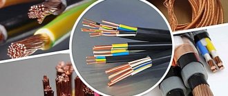
What are electrical cables made of?
The main conductor of electric current is aluminum or copper conductors. The larger their diameter, the higher the cable's capabilities.
Aluminum wires are cheaper, but they are more likely to deteriorate and have a lower electrical conductivity coefficient.
Copper cable is durable, does not break at bends and is capable of carrying more current than aluminum cable with the same diameter.
It is recommended that all wiring in the house be of the same type. This is due to the fact that to connect products from different materials, a special adapter will be required so as not to create a galvanic couple. In this case, oxidation and destruction of the wires occurs, which can lead to a short circuit.
The main cores are covered in braids made of rubber, polyethylene or PVC. Often several of these insulated conductors are combined into a bundle, which in turn is covered with a protective sheath.
Cable for apartment sockets
The optimal cross-section of wires serving apartment socket groups is 2.5 mm 2. This allows them to withstand currents of up to 27 A, which corresponds to a total power of approximately 6 kW. The use of conductors with a larger cross-section, for example, 4 mm 2, is impractical because:
- Such cables simply cannot fit into the terminals of socket mechanisms.
- Laying such cables is significantly more expensive and is not economically feasible.
And there is no practical need for thicker cables, because... It is rare to find household electrical appliances plugged into an outlet whose power exceeds 3.5 kW. Thus, by placing cables with a cross-section of 2.5 mm 2 in the wiring of the socket groups, you can sleep peacefully: they are able to withstand any electrical appliances, even if they operate for a long time.
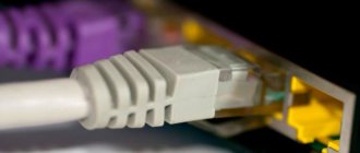
Difference between cable and wire
The wire is a lightweight structure consisting of 1-3 insulated cores. It is less secure than cable and has a simpler internal structure.
A cable is a wire of a more complex structure. In addition to several cores separated from each other, it has a double layer of insulation, a gasket, a screen and is recommended for use in residential areas.
Lighting system wire cross-section
Surely, you yourself understand that lighting fixtures place the least amount of stress on apartment electrical wiring. Therefore, a wire cross-section of 1.5 mm 2 is quite sufficient for a standard apartment in an apartment building. However, when laying the wiring, you should be absolutely sure that the total load of each lighting group does not exceed 3.5 kW. Due to the traditionally low load, all apartment lighting, as a rule, is reduced to one group, served by a 1.5 mm 2 cable.
A wire cross-section of 1.5 mm2 is quite sufficient for wiring that supplies power to lighting fixtures
So, to summarize, I’ll just remind you of the bare numbers. Most often, the cross-section of wires in a city apartment is:
- input cable – 3×10 mm 2 (single-phase network), 5×2.5 mm 2 (three-phase network);
- electric stove (hob) – 3×6 mm 2 (single-phase network), 5×2.5 mm 2 (three-phase network);
- rosette groups – 3×2.5 mm 2;
- lighting devices – 3×1.5 mm 2.
However, I must emphasize the phrase “most often” that I used. If you initially plan to install very powerful devices in your apartment, then before laying the electrical wiring you should make the necessary calculations so as not to make a mistake in choosing cables of the required cross-section. The best option is to contact a professional electrician.
Conclusions and useful video on the topic
For more complete information regarding the installation of electrical wiring in the apartment area, it is recommended to watch a video describing the processes.
Familiarization with the video will enrich your existing experience, which will only have a positive impact on the quality of work.
Electrical wiring done by hand in a city apartment is a completely acceptable option. However, there are some “buts” in solving the issue in this way.
Firstly, you should not take on this matter if you do not have the slightest experience in electrical installation. Secondly, when planning to carry out work independently, you first need to think about your own safety and only secondarily about your own benefit.
Share with readers your experience of independently installing wiring in your apartment, connecting sockets and switches. Please leave comments, ask questions about the topic of the article and participate in discussions - the feedback form is located below.
Wire cross-section for entry into the apartment
Hello, I would like to rehang the panel in an apartment (new building, complete renovation) and accordingly I need to lengthen the input a little. I'm thinking of replacing it completely. Thinking about the section. The input is limited by a circuit breaker in the floor switchboard at 63A. On the Internet, or rather on Mastercity, there are two links to PUE tables » > » > According to the first, I need a section of 16 squares, and according to the second, 10 is enough. The question arose, how much is needed?
Nowadays it is almost impossible to find a cable with a non-undersized cross-section, so it is advisable to choose 16 mm2, because according to table 19 GOST R 53769-2010 back-to-back 10 mm2 is 63 A
At the same time, formally 10 mm2 is just 63 A, so it is an acceptable option, however, keep in mind that the machine can pass 1.45 nominal for up to 1 hour, and for a cable over several minutes this is no longer a short-term excess of current and Overheating may occur and damage the insulation.
In short, 16 mm2 is better, but 10 mm2 is also acceptable.
Quite right - 16 squares.
Alexiy wrote: At the same time, formally 10 mm2 is just 63 A, so it is an acceptable option, however, keep in mind that the machine can pass 1.45 nominal values up to 1 hour, and for a cable over several minutes - this is no longer short-term excess current and possible overheating, which will damage the insulation.
as an option, use a -FRLS cable; it has a permissible core temperature of 90C for several hours instead of 70 and allows emergency overloads. but at the price of 16mm2 it might be cheaper.
So as not to think about it in the future. AB 40A - 6mm2 AB 50A - 10mm2 AB 63A - 16mm2 AB 80A - 16mm2
correct me if I'm wrong av 10a - 1.5 mm2 av 16a - 2.5 mm2 av 25a - 4.0 mm2 av 32a - 6.0 mm2 av 40a - 6.0 mm2 (I doubt it) av 50a - 10.0 mm2 av 63a - 10.0 mm2 av 80a - 16.0 mm2
Ok, thanks everyone. In general, if the wire is from the market, then it’s definitely 16 squares.
And a related question, so as not to clutter up with topics, is it necessary to use corrugation when laying wires in a screed? After all, the medium is fireproof, cooling is better and the diameter is smaller. VVG cable, house - monolith.
StarWind wrote: Ok, thanks everyone. In general, if the wire is from the market, then it’s definitely 16 squares.
And a related question, so as not to clutter up with topics, is it necessary to use corrugation when laying wires in a screed? After all, the medium is fireproof, cooling is better and the diameter is smaller. VVG cable, house - monolith.
The corrugation will save you in case of emergency. if a crack forms in the screed, which will easily rupture the outer sheath of the cable.
user0552 wrote: correct me if I'm wrong av 10a - 1.5 mm2 av 16a - 2.5 mm2 av 25a - 4.0 mm2 av 32a - 6.0 mm2 av 40a - 6.0 mm2 (I doubt it) av 50a - 10.0 mm2 av 63a - 10.0 mm2 av 80a - 16.0 mm2
63 A - 16 mm kV 80 A - 25 mm kV Ampere must be capitalized - this is the person’s last name.
Alexiy wrote: Nowadays it is almost impossible to find a cable with a non-undersized cross-section
Well, why: when I bought a cable for myself - and this is about 100 m, I did not hesitate to take a caliper with me and before buying I measured the diameter of the cores
Alexiy wrote: Nowadays it is almost impossible to find a cable with a non-undersized cross-section.
If you need 4mm, take the one that says “6 mm”, if you need 1.5 mm, buy it, which is passed off as “2.5 mm”, and so on. But it's better to do this:
Magirus wrote: without hesitation, he took a caliper with him and measured the diameter of the cores before purchasing
Magirus wrote: I took a caliper with me and measured the diameter of the cores before purchasing
there is an error of 0.05, and this. 1.79mm is 2.5mm2, and 1.74 is 2.35mm2 (narrower), but in real life you can easily make a mistake by a factor of ten with such a rough instrument for these measurements, and this. 1.69 - 2.25mm2 I measured 5 or more options with a micrometer - the best that was 2.4, the worst - 2 with microns (!). At the stated 2.5mm. And 6ka pvs turned out to be generally less than 5 (something around 4.7-4.8, emnip).
Tsypra, approximately, from memory, was a long time ago.
I wonder if you measured the PVC correctly?
lightning wrote: If you need 4mm, take the one that says “6 mm”, if you need 1.5 mm, buy it, which is passed off as “2.5 mm” and so on.
Most manufacturers cruelly cut the multi-core, taking advantage of the difficulty of measuring resistance and cross-section. For example, I buy PVA 2.5 and get the real 1.35. I checked one core with a micrometer and multiplied. Monofilament is not cut so cruelly.
I wrote about monocore
helios1969 wrote: there is an error of 0.05, and this. 1.79mm is 2.5mm2, and 1.74 is 2.35mm2 (narrower), but in real life you can easily make a mistake by a factor of ten with such a rough instrument for these measurements, and this. 1.69 - 2.25mm2 I measured 5 or more options with a micrometer - the best that was 2.4, the worst - 2 with microns (!). At the stated 2.5mm. And 6ka pvs turned out to be generally less than 5 (something around 4.7-4.8, emnip).
Tsypra, approximately, from memory, was a long time ago.
Well, as if I didn’t think about the error of measurements with a caliper. You're right. But I have a bar with a pitch of 0.02 mm
Well, at least the blatant bullshit is already “cut off.”
Yes, there are still many factors to take into account: we bought a VVG-NG 2 x 2.5 cable from us in Kyiv - “Odessa cable” - it looks good, it bends with effort. And then I bought more from Leroy Merlin - it’s like Dneprpetrovsk does, but in appearance - the outer shell is visually thinner and the veins bend like tin (roughly how it feels). Either some kind of alloy, or, I also read, annealed copper or vice versa. But I’m not sure - someone who knows can correct me
Curious: why after the introductory 32A is there 40A (at the surge arrester)? Or: only for the refrigerator there is an AB 16A + RCD. Hmm, it’s probably like in a decent canteen, if for some reason the RCD goes off, the food won’t go rotten? Or on the gate AB 16A + RCD (probably a 5 kilowatt motor), the same thing - roller shutters? And the garage has no RCD. In fact, the loads, at least the ones indicated, are small. Why so many lines and RCDs is unclear. Or, apparently you like 4-pole AVs, but for some reason there are 3 at the input? I'm not saying there's anything wrong. Just commenting. And another question:
MIK wrote: The meaning of 1P+N machines has been described on the site more than once.
If possible, a link where this is described: I have never seen such a description. Curious to see what people think about this. But your explanation is wrong. The sum of AB currents after the RCD should not exceed In RCD. And further:
Metall wrote: Quote Message from SKL View message In front of each 25A RCD there should be an equal current circuit breaker, or better yet with a lower rating is not correct..
In this case, SKL is right. Perhaps Mr. Metall misunderstood what SKL wrote. Usually it sounds like this: “the rated current of the RCD should be chosen equal to, or one step higher than the rated current of the circuit breaker protecting this RCD.”
Electrolamp wrote: Ampere must be capitalized - this is the person’s last name
More precisely, apparently, like this: in the rules of the Russian language, abbreviations of basic units, if it is someone’s last name, are written with a capital letter, and subordinate units with a small letter, For example: ampere - A, kiloampere - kA, volt - V, kilovolt - kV etc. In any case, that’s what I was taught about 50 years ago. Now it may be different.
Preparation of jumpers and connection diagram
Making a jumper in a non-breaking way
Conductors need to be prepared for connection in the panel. To do this, you need to strip the ends from the insulation using a knife or a special tool. The cores should be inserted into contact and tightened well with a screwdriver.
During operation, you need to pay attention to the following:
- The insulation should not get caught in the clamp.
- The exposed part of the wire should not stick out from the contact over a large area. This requirement is made by network organizations that seal meters. This helps prevent illegal connections from outsiders.
- The upper screw is tightened first, followed by the lower one.
The last step is to check the reliability of the fixation. The veins need to be carefully touched and pulled apart. The conductor should not swing or stagger.
Connection of machines
Next you need to connect the neutral wire. It is connected using a jumper from the lower right contact of the automatic two-pole switch to the third contact of the electric meter. The ends also need to be stripped of insulation, connected and tightened with screws. The wires must not touch each other. Be sure to leave a gap between them.
Now you need to connect the outgoing wires from the meter. First, the phase is connected through a jumper to the upper contact of the machine. The ends are stripped and joined. The phase also needs to be distributed among other sources in the directions of the machines.
There should be one contact left from the electricity meter in the apartment. This is the outgoing zero contact, which must connect to the zero bus. Usually it comes complete with a plastic box. Length, dimensions and configuration vary by manufacturer.
Input cable to the apartment cross-section according to the standards
The cable with which a consumer object (house, apartment, workshop, store, etc.) is connected to a power source is called an input cable. Most often, the input cable is connected directly to the electrical energy meter. To protect the meter, a circuit breaker may be installed in front of it, but such a scheme must be agreed upon with the electricity supplier and reflected in the technical specifications. In this case, the circuit breaker is sealed to prevent energy from being drawn to the meter.
Selection of RCDs and automatic devices
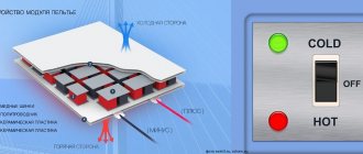
The circuit breaker provides short-circuit protection, but it is not capable of detecting leakage current that may flow into the electrical equipment frame when the insulation coating is broken or through the human body. For these purposes, a residual current device (RCD) or differential circuit breaker is connected to the panel.
These devices are switching devices that constantly monitor the differential current of the electrical wiring, and if it deviates from the permissible value, a shutdown is performed. The principle of operation is clearly illustrated in the picture.
How does an RCD work?
The main purpose of these devices is to provide adequate protection in the event that a person becomes energized and to prevent fire that may be caused by a leak.
Main characteristics of the devices:
- rated current parameters (they must correspond to the circuit breaker or a higher value is allowed);
- operating voltage (220V or 380V, respectively, for single-phase and three-phase devices);
- The permissible leakage current parameter for household devices is considered safe 30mA.
In our circuit, it is necessary to install a 16A RCD with a permissible leakage current of 30mA (elements C – F). These differential protection devices do not need to be installed for hallway and kitchen lighting.
RCD for 16A
Input cable into the house - types of connection and choice of brand
The power supply to the house is connected from the power line, the connection is made on the nearest pole (support). In some cases, when power line supports are remote from the site (for example, they are located across the road from the connected house), it may be necessary to install an additional support.
The input cable can be laid in two ways:
by air, from the power line support to the input distribution device;
underground in a prepared trench.
Air input
. Over-the-air power supply can be carried out by cable or self-supporting insulated wire (SIP).
Most types of installation cables (VVG, AVVG, etc.) are not intended for air suspension without the use of additional support. Such a support can be a stretched steel cable or wire. In the first case, the wiring is called cable, in the second - string. The ends of the cable or string are attached to the overhead line support on one side and to the building structures at the entrance to the house on the other. The cable being laid is rigidly attached to a supporting steel cable or wire.
Bare, uninsulated wires of overhead power distribution lines are gradually being replaced by self-supporting insulated wires (SIP). Power lines with insulated wires (VLI) are more reliable. The use of SIP eliminates the most common types of damage to overhead lines with bare conductors - overlapping of wires and their shorting by foreign objects. SIP is the most preferred option for an over-the-air input wire, which can be used when connecting to both an overhead line (line with a bare wire) and a VLI (line with an insulated wire).
The aerial connection of the input cable to power lines up to 1000 volts is carried out using SIP - 2 or SIP - 4 wires. The neutral and phase conductors of these wires are insulated. The zero conductor of SIP-2 is equipped with a steel supporting core, on which the wire is suspended. SIP-4 does not have a core; when it is suspended, the load is carried by the current-carrying conductors themselves.
Underground input
. For laying in a trench, a cable is selected that can withstand the weight of the soil and the shear force that occurs during its settlement. Therefore, the most suitable for this purpose are the VBBbShv cable with copper conductors or the AVBbShv aluminum input cable. The core insulation of these types of cables is made of PVC plastic. On top of the insulated cores there is a layer of PVC or unvulcanized rubber filling and an inner polyvinyl chloride sheath. This is followed by armor made of galvanized steel tape and an external pressed-out protective hose. VBBShV and AVBBShV conductors can be made single-wire or multi-wire, and the cross-section of the conductor can be in the shape of a circle or a sector.
Features of air and underground input. The advantages and disadvantages of installing the input cable over the air and underground are reflected in the table:
over-the-air input cable
over-the-air input cable
How to connect the phase and neutral wires
Simultaneous disconnection of phase and neutral is justified especially in situations where three-phase voltage is introduced into a house or non-residential building. In such situations, there is a greater risk that one of the phases may short circuit to zero. This is a short circuit mode to which the machine protecting this phase must respond. But in those fractions of a second while it is triggered, an overvoltage will occur in the other two phases. That is, instead of the required 220 V, there may be all 380 V - the voltage difference between the two phases with a conventional three-phase connection.
Not a single household appliance is designed for such voltage, and the more powerful it is, the more current it passes, and the greater the likelihood of it burning out due to overvoltage. Where the fuse of a low-power device immediately blows, powerful equipment will still “tolerate” a heavy load for some time, and during this time the switching power supply or transformer may fail. Therefore, it is preferable to protect equipment such as boilers, dishwashers and washing machines with two-pole circuit breakers that cut two circuits at once.
Keep in mind that phase imbalance is also harmful to the source that powers the building. A generator, a transformer booth, a substation - all this will deteriorate very soon. For such purposes, there are special three-phase circuit breakers, which, in the event of a large imbalance or failure in one of the phases, can immediately turn off all three phases simultaneously. For more critical circuits, it is recommended to connect a four-phase circuit breaker, which also de-energizes the neutral wire.
Input cable to the apartment
General-purpose installation cables, such as VVG, are used as the input cable into the apartment. For systems with a working and protective neutral wire, the number of cable cores must be at least three.
The apartment input cable connects the floor panel and the apartment panel. In old-type houses, there may be no internal panel, and distribution within the apartment is carried out through connection boxes. When carrying out renovations in an old apartment, it is advisable to provide for the installation of an interior panel.
Important to know: Cable entry into the apartment is carried out using a two-wire or three-wire circuit. Input into apartments of modern houses is carried out using the TN–S or TN–C–S system using three wires:
L - phase conductor;
N - working neutral conductor;
PE - protective neutral wire.
In old houses, a TN-C grounding system is implemented, in which the working and protective neutral wires are combined, that is, power is supplied through two wires - L and PEN.
Standards for connecting the machine in the panel according to the PUE
Government authorities have requirements for shields and their installation that are specified in the PUE and must comply with GOST 51778-2001:
- the installed shield must comply with the documentation, which clearly reflects the number of machines and their power, as well as the class and degree of protection;
- the voltage symbol should be installed on the lid - 380V or 220V;
- the phase must be connected to a fixed contact;
- material of manufacture – metal or plastic coated with non-flammable paint;
- make markings on the wires indicating the devices that are connected;
- install jumpers from bus drives between the machines;
- There must be grounding of the box body. The case must have ears so that the electrical inspector can install the necessary seals.
Reasons for replacing cables
Complete or partial replacement of electrical networks usually needs to be performed in two cases:
- Wiring age. Major renovations are recommended to be carried out 15-20 years after moving into a new apartment. During this time, the installed communications wear out, becoming a source of potential danger for residents.
- Redevelopment and renovation of premises (especially with the addition of powerful household appliances). Modern electric stoves, washing machines, and dishwashers place increased demands on wiring. It is not advisable to connect them to old electrical networks due to the mismatch of characteristics. When planning to purchase such units, it is better to update communications in individual rooms, for example, in the kitchen or bathroom.
Regardless of the reason for replacing electrical networks, work should begin with drawing up an electrical wiring diagram and selecting cable products.
Installation and connection
Accepted colors of phase, neutral and ground wire
Before starting work, it is necessary to de-energize the room. Using a tester, it is checked whether voltage remains on the conductors. Using the probes of a screwdriver, you need to touch each core one by one. If the light does not light up, you can start working. It is prohibited to work with electricity turned on
It is also important to prepare tools in advance and provide the master with an autonomous light source
When connecting wires in a panel, it is important to remember that the colors of the wires indicate their purpose. The core can be completely painted in one color or another or have a color mark at the entrance to the device, that is, at the ends of the conductor
The following scale is used:
- Phase – gray, black.
- Zero is blue.
- Grounding – yellow-green.
The wire for installing the electrical panel must be laid in such a way that there are no sagging or unnecessary bends. To do this, the length of each segment is determined in advance with a small allowance of 2-3 cm.
All connections to the machine are made using jumpers. Single-wire rigid wire can be used for this purpose. If possible, it is better not to use jumpers, but to do everything through the connecting core. Thanks to it, the contact will be reliable and the appearance will be aesthetic.
Currently, I have chosen electrical panels and devices from ABB.
But knowledge of modular and panel products from Schneider Electric, Legrand, Hager allows me to assemble electrical panels from components from any manufacturer. Therefore, when choosing a company, I always go to meet the customer of the shield.
But it should be noted that the prices from these manufacturers are almost the same. The only difference is different series of devices, but even if they are similar in parameters, they are also the same.
Below I will give a comparative calculation of the cost of an electrical panel of different series of ABB and Schneider Electric for one of the orders (the calculation is already outdated, but is still relevant).
Comparison of prices for automatic machines, RCDs, switches from ABB and Schneider Electric.
Electrical panels, at the request of the customer, can be equipped with various additional “wants” and protections: light indicators, digital voltmeters, contactors with on/off switching of all or part of the load, timers (time relays) for turning on the load according to a schedule, voltage control relays, etc.