In this article we will look at how to replace a two-wire wiring with a three-wire one with a protective grounding system.
When organizing household power supply systems, the grounding procedure is a mandatory step. This is the easiest way to avoid electric shock when wire insulation is damaged and/or short circuits occur in the network. Grounding can also provide protection against failure of various household electrical equipment. Unfortunately, in many old (and not only) houses and apartments there is no grounding of electrical wiring; instead, grounding is used, or there is no protection at all. Grounding, as practice has shown, is not the most reliable method of protection, since this system, in fact, only protects equipment when short circuits occur. If the insulation is damaged and current leaks onto the housing of an electrical device, the grounding system will not be able to protect a person from electric shock (if he accidentally touches the exposed part of the housing).
Tile cutting device
It's been a while since I added anything here.
Preface: why exactly this way, and not using a machine.
Firstly, I’m not entirely sure that the so-called wet tile cutter will cope with this task, and I’m sure that a cheap one definitely won’t cope, and an expensive one, let’s say from 50 thousand rubles. Maybe he can handle it, maybe he won’t.
Therefore, with such a daisy, I refused to buy an expensive machine because the work will not pay for such costs, and cheap rubbish is not needed.
This means we work the old way, proven and cheap.
In general, I have a tile cutter, it’s not the worst, it successfully coped with various tasks, but there was a problem with this porcelain tile. It (porcelain stoneware) breaks off along the cut line completely uncontrollably, it can clearly break, or the arrow can go to the side. The second problem is that the surface is very fragile, just like a glass surface; even behind the roller, chips can occur. A diamond cup can also chip even with a light touch. There is no need to talk about a diamond disc at all, the surface after it is jagged and chipped, which means that not every water-powered tile cutter can cope with such a task.
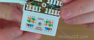
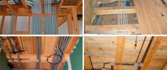
Applying markings to the laid cable
Electricians often have to deal with a situation where it is necessary to repair an electrical panel or network, but the equipment is connected in such a way that it is not clear where the phase and neutral are located, and where the ground is. This happens when the installation of the system is carried out by an inexperienced person, without special knowledge, for whom not only the markings, but also the location of the cables inside the switchboard are incorrect.
Another reason for such problems is the outdated and irrelevant qualifications of electricians. The work is done correctly, but in accordance with the old standards, so for the specialist who comes as a “replacement”, it becomes necessary to “punch” with a tool where the zero is located and where the phase is.
There is no point in arguing about who is to blame and whether anyone should do the repairs themselves; it is better to decide how to apply the correct and understandable markings.
So, current standards establish that color markings on electrical conductors cannot necessarily be placed along their entire length. It is allowed to mark it only at the points of connection and connection of contacts. Therefore, if you need to mark cables without markings, you should buy a set of heat-shrinkable tubes or insulating tape. The number of colors depends on the specific circuit, but it is advisable to purchase a standard “palette”: zero - blue, ground - yellow, and phases - red, black and green. In a single-phase network, naturally, the phase is indicated by one color, most often red.
The use of colored electrical tape or heat-shrinkable casings is also suitable for situations where the existing wire does not meet the requirements of the PEU. For example, if you need to connect a four-core cable to a three-phase network with wires of white, red, blue and yellow-green. These wires can be connected in any order, but be sure to place cambrics or windings of electrical tape with the “correct” colors at the connection points.
In addition, you should remember the problematic situations described above when installing a new unit or connecting equipment. The lack of clear and understandable markings can significantly complicate further maintenance of the circuit, even for the person who installed it.
If you find that your distribution panel or network uses wire symbols that do not meet current requirements, do not rush to replace them. Before repair or dismantling, the wiring is subject to the standards that were in force at the time of its installation. Additionally, if the network is functioning properly, replacement is not required. And when commissioning a new (or converted old) electrical network, you will have to take into account and comply with all modern requirements and rules.
Is it possible to connect wires by twisting
Very often, especially in old houses, we start removing old wallpaper, unscrewing old sockets, disassembling dilapidated junction boxes and what do we see: a lot of wires twisted together and wrapped in insulation:
I know that many electricians still twist wires this way and consider it the most reliable. However, from a fire safety point of view, no firefighter will approve of electrical connections in an apartment made only by twisting.
The fact is that sometimes you have to connect wires of different sections and different materials, for example, copper and aluminum wires. And it is precisely for such cases that twisting is unacceptable. For example, with the same load on the network, it will act differently on thick and thin wires twisted together, one of which will feel good, and the other will heat up.
Briefly about household grounding systems
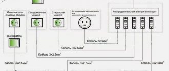
Since 2003, a decree has come into force, which contains updated requirements for the construction and refurbishment of apartment buildings (and other buildings), including the installation of grounding systems. According to the rules, buildings must be equipped with a riser consisting of 5 wires, where the 5th serves as a grounding conductor.
Regarding private houses. Grounding systems (if not available) must be installed by residents themselves. Typically, such a system is a grounding loop dug into the ground. The circuit, as an option, is made of 3-4 steel stakes driven into the ground and combined into a single chain.
To organize a grounding system in a house/apartment, a three-core cable is used, the connection of which is carried out according to a simple diagram. Let's consider this issue in more detail.
How to connect wires of the same material and cross-section
How to connect wires of the same material and cross-section to each other, for example, copper to copper for 2.5 squares? This is the simplest case, and twisting may well be suitable here:
Only instead of regular insulating tape, the store sells caps for twisting:
You need to take the cap and screw it onto the twist:
How to connect a switch with one key
If there is a switch in the room, then the connection in the box will be a little more complicated than with only sockets. There will also be three groups of conductors, but the connection is of a different type. Available:
— input cable – from another box or directly from the switchboard;
— wire for the chandelier;
- wire from the switch.
The circuit should work as follows. Power (that is, phase) is supplied to the switch key. From its output a wire is supplied to the lighting fixture. As soon as the switch contacts close, the chandelier will light up. The ground and neutral wires must be twisted together.
Is it possible to connect wires of different sections of the same material?
If, for example, you need to connect wires of different cross-sections (they are also suitable for the same cross-section) and the same material (copper or aluminum), then in this case the special connecting blocks presented below are well suited.
They have different numbers of inputs: in the figure, respectively: 2, 4, 6.
That is, this is a “sort of” twist for 2, 3, 4, 5 or 6 wires.
Moreover, if you need to connect 3 wires to each other, then for this you can use a block that has 4 or 6 inputs:
By reading my blog, you are probably making repairs.
this page to your bookmarks .
This is where all the useful home improvement stores are located. The block is simply pressed tightly onto the wires:
You need to understand that after connecting the wires in this way, they can no longer be removed from the block. Therefore, if you have never tried to work with such devices, buy a few of them in a store with a supply and practice at home. They cost pennies.
How to connect copper and aluminum wires
When you need to connect wires made of different materials (copper and aluminum), and even different sections, in this case you will be helped by pads whose inputs are filled with a special paste that prevents oxidation:
The same pads, of course, are suitable for wires of the same cross-section and the same material. As in the previous case, if you have already put wires on them, then they will no longer be removed from the blocks. Therefore, think through all your connections in advance.
Design features
The design of electrical plugs is divided into several types. You need to familiarize yourself with the technical characteristics, advantages and disadvantages of each in more detail.
Non-removable fork device
The design features of non-separable modifications are the same everywhere. The pins are installed at intervals of 19 mm into a strip made of plastic; conductors are pressed into it. The bar is equipped with two protrusions, the purpose of which is to guide the wire. The bypass is important because it eliminates the possibility of the plug cord breaking if significant force has been applied to it.
The wire and pins are filled with molten plastic. This is ensured by a high degree of tightness of the case with the power cord securely fixed in it.
Device of a collapsible three-pole design
Not so long ago, only collapsible structures were used to connect electrical appliances. Today they are still used by a large number of Russians. You cannot do without such a part if you need to replace a cast mechanism that has failed. The advantage of such a fork is its maintainability and the ability to use it repeatedly. It can be dismantled and installed on another cord without much effort.
Design device type C1-B
This design is incredibly simple in its implementation. It consists of two halves of a plastic body, two brass pins, fasteners and a clamping bar.
Design features of the collapsible structure type C6
The design is also not particularly complicated. Modifications are available with or without a grounding contact. Designed to operate devices with a power of no more than 220 W. The pins are made of brass; contact pads with threads are pressed onto them for screwing wires. The pins are attached to the base of the plug. An additional grounding contact can be installed in the housing, which has the shape of a brass strip. There is also a strip for securely fastening the wire with a plastic gasket.
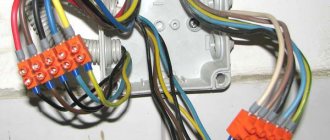
Connecting blocks - latches
There are also jumper blocks that will allow you to connect wires together, but if you make a mistake, you can disconnect any of the connected wires. These are the so-called latches:
For latches, you should definitely check with the seller in the store about the possibility of connecting wires of different materials and cross-sections.
Differences
Five of them can be distinguished:
- number of conductors
- number of insulation layers
- quality of insulation and conditions of its use
- digital and letter markings
- lifetime
Let's take a closer look at how they differ and how they are similar?
One of the options for connecting wires in a chandelier
If you need to connect a chandelier, then one of the options for connecting the wires coming out of the ceiling with the wires coming from the chandelier would be to use blocks in which the wire connection is secured using screws:
For a chandelier, the option of using wago type terminals, especially if the wires coming from the ceiling are short, will not be very good, since, as already mentioned, in this case the wires cannot be removed (for example, you will need to change the chandelier or wash it) and you will have to cut them off. In the case of terminals with a screw connection, it will be enough to simply unscrew the fastening screws and release the wires.
Which fork is better - collapsible or cast?
The cast plug is more reliable; its main advantage is the density of the contacts that connect to the pins. The cast model uses spot welding, soldering and crimping. Another advantage of the model is its tightness.
But there are annoying drawbacks: it cannot be disassembled to eliminate the cause of the breakdown. If the cord frays at the base due to prolonged use, then the only solution is to cut off the molded plug to replace it with a collapsible model. It is possible to completely change the cord and plug to a new one, but to do this you will have to disassemble the device.
However, if such a replacement does not frighten you, it is better to purchase a cast product, especially since, due to its increased reliability, such a fork fails much less often than its collapsible counterparts.
Important Notes on Wiring Connections
Let us note important points regarding electrical wires.
- All wires twisted together should not dangle somewhere in the air! They must be placed in a junction box.
- Do not try to remove the wire from terminals that are not intended for this purpose. For example, there are craftsmen who manage to remove wires from wago terminals. But I do not recommend doing this, since such removal is always associated with deformation of the wire. And this is unacceptable, because the load on the network should be experienced by whole wires, and not half-broken ones, which can lead to short circuits.
For all wire connections, ensure that the bare ends of the wires are completely hidden in the connection block. That is, try to make the connection so that after this connection it would be impossible to reach the bare end of the wire with your hand.
This is where the article ends. We have studied in detail the issue of how to connect wires in an apartment. Now, when moving the socket from one place to another, you can easily extend the wires by laying them in the wall and making the correct connection.
Did you like the article? Share with your friends!
There are now so many convenient and varied terminals for connecting wires, not like before - electrical tape - and nothing else.
For an ignorant person, connecting 4 ends of the wires was not yet possible, but 6 ends is already a serious problem!
Thanks for the clarification, we usually soldered the wiring, but with special pads it is much easier.
The topic is very important. Indeed, many people connect wires at random, and this poses some dangers, including fire. If a person does something on his own, then first he needs to consult with the experts in this matter.
What detailed instructions, thank you! I would like to see everything explained to our children in the same detail during labor!
Thanks for the useful information, twists are a thing of the past.
Interesting article . I learned something new for myself. Thank you .
A good article, detailed with pictures. Everything is very clear, thank you.
They installed these pads for me at home... It would be better if they did everything with twists. The socket doesn't work and that's it. I called an electrician, he immediately said that the problem was in the pads and that they (the problems) would appear periodically. I reached into the box and sure enough: I turned the wire in the block, the socket started working. But problems cannot help but appear: in the block the wires are pressed with thin petals, very similar to steel ones. So I'll look for something else instead of pads...
I’ll honestly tell you that I made all the connections at home through the blocks. The kitchen has a lot of electricity supply: 3 sockets, heated floor. dishwasher, hood, microwave and everything is on blocks that are hidden in junction boxes or sockets.
I don’t argue that there are cases, but these are the exception rather than the rule. There might have been a defective batch. And the examples are very different. Some people's walls fall apart after plastering, while others have had no problems for 25 years. But this does not mean that now there is no need to plaster the walls. Somewhere the technology was broken. Therefore, here we need to study the problem, look deeper into why this is happening. And if twists were the most reliable, then firefighters would not prohibit them.
Thank you very much for the instructions! It became more or less clear what was what.
Write if you have any questions!
Hello. I am installing electrical wiring for a mini-bakery. Everything is great except for one thing. The fact is that I am opening a company in a remote corner from civilization in a small village. The city is 2000 km away and only by plane. Therefore, I stocked up on everything in advance. Except of course the wires. And then I somehow found the usual white two-wire and three-core aluminum noodles with a cross-section of 1.5 sq. mm. and copper three-core 2.5 sq. mm. Three-phase electrics. I installed 2-wire noodles for lighting, and three-wire for sockets with chargers. I have only three equipment supplying 380 W. Dough mixer 2.4 kW, Flour sifter 1.2 kW, Oven 19.2 kW. Since there is no choice, all three of them carried out wiring with a cross-section of 2.5 sq. mm. In addition to the stove, the dough mixer and flour sifter work perfectly. But when I turn on the stove after 5 minutes, the RCD 63A 30Ma turns off the electrical supply. I think this is due to the cross-section of the wire because... I found on the instructions that you need to use a wire with a cross-section of 6 sq. mm. How can you get out of the situation? Of course it would be great to find a 6 sq. mm wire. But I only have 2.5 sq mm. Please tell me whether it is possible to use a three-core wire as one wire, i.e. connect all three to one?
Yes. It would be optimal to make all three wires of one wire 1 phase (7.5 sq. mm), another 3-core wire for the second phase, and also for the third phase, also for zero (also 7.5 sq. mm, respectively), and grounding. With such loads (about 60 A), no terminals will withstand (except screw ones, but for myself I would not risk it), it is necessary to twist, which should be tinned and soldered (use acid-free flux solder and a simple gas torch + futorka (copper tube with a diameter of 25mm, one end is rolled onto a holder so that the solder does not leak out, approximately 3cm deep), or a welding machine and a copper electrode (boil the ends of the twists until all the cores are welded together into a ball at the end).
This is the best and least expensive option.
Thank you very much for such an article, very useful information for those who do not understand electricity, but it is very necessary for repairs. Once again a huge THANK YOU.
What can you say about clamp-couplers that pierce insulation, how safe are they?
Good afternoon. I write about what I have personally tried or know what other masters do. Where there is no information, I don’t write about it.
Good afternoon Is it possible to connect the copper wire coming from the switch and the aluminum wire going to the chandelier through the block? This is absolutely not possible or can be left. Thanks for the answer
Yuri! Just through the block it’s possible. This is one of the few ways. Direct contact of copper and aluminum will lead to oxidation of the aluminum wire as a result of electrochemical corrosion and loss of contact with subsequent heating. In the best case, the light will go out, in the worst case, the insulation (or the switch itself) at the heated contact will light up. In addition, the article is rather weak for understanding how to connect wires. There are no other methods: soldering, welding and crimping. And the pros and cons of each connection are not disclosed. I believe that connecting via terminal blocks is also not the best way. First: screw terminal blocks require periodic tightening; self-clamping and spring-loaded screw terminal blocks may not cope with tightening the power wire, which is loaded to its nominal value and begins to heat up. Second: even the Vago terminal blocks are very weak for normal power lines. My opinion: to connect wires for lighting yourself, you can use terminal blocks, and for power (sockets) use the crimping method, as a relatively simple method for doing electrical work on your own (you will have to spend money on crimping the sleeves, if you don’t mind buying a hair dryer for heat shrinking, you can take a turbo lighter and practice with it on a couple of joints and everything will work out (it’s not God who crimps pots). By crimping using copper-aluminum adapter sleeves you can also solve your problem (this is the best way for strength, since aluminum has high fluidity and in a screw terminal, the contact will weaken).
If I were to write an article, I would cover all connection methods and give the pros and cons of each. In conclusion, I would recommend those methods that are convenient for beginners. Well, in parallel, it would be necessary to write an article about choosing the type of cable that is allowed for use in electrical wiring, as well as choosing the cross-section of conductors and circuit breakers in the panel. General rules for constructing electrical panels, indicating which lines should be separate and which are recommended to be separated separately. Just connecting the wires is not enough to understand the issue.
Color marking of phase, neutral and ground
For wiring and installation of electrical networks in domestic and industrial facilities, multi-core cables are used, each wire inside of which is painted in a distinctive color. This is necessary, as already mentioned, to simplify the installation and maintenance of the network.
So, for example, if a network repair is carried out by a person who was not involved in its installation, he will immediately understand the working diagram by the color of the wire connected to devices and power supplies. Otherwise, it will be necessary to punch through zero and phase manually using a probe. This process is not easy even when checking new wires, and if it is necessary to repair old wiring, it will completely turn into a test, since earlier, in Soviet times, wires were not marked, and they were all covered with a black or white insulating sheath.
According to developed standards (GOST R 50462) and electrical installation rules, each wire in the cable, be it zero, phase or ground, must have its own color, which indicates its purpose. One of the main requirements of electrical installations is the ability to quickly and accurately determine the function of a wire in any section. Color marking is best suited to solve this problem.
The wire markings presented below are designed for AC networks and electrical installations (transformers, substations, etc.) with a solidly grounded neutral and a rated voltage of no more than 1 kV. Most residential and administrative buildings meet these conditions.
Protective and working neutral conductor
Zero or neutral on electrical diagrams is indicated by the letter N and is painted throughout in light blue or dark blue without additional color designations.
PE – protective zero contact or simply “ground”, has a characteristic color of green and yellow lines alternating along the wire. Some manufacturers paint it a uniform yellow-green shade along its entire length, but GOST R 50462-2009, adopted in 2011, prohibits the designation of grounding in yellow or green separately. In combination green/yellow, these colors can only be used in situations where they indicate grounding.
PEN wires used in today's outdated TN-C systems, where ground and zero are combined, have more complex markings. According to the latest approved standards, the main part of the wire throughout its entire length should be painted blue, and the ends and junctions should be painted with yellow-green stripes. It is also possible to use wires with opposite markings - a yellow-green wire with blue ends. It is rare to see such a wire in modern buildings, since the use of TN-C was abandoned due to the risk of electric shock to people.
- zero (zero working contact) (N) – blue or light blue wire;
- earth (zero grounding) (PE) – yellow-green;
- combined wire (PEN) – yellow-green with blue marks at the ends.
Phase wires
The cable design may contain several current-carrying phase wires. Electrical codes require that each phase be identified separately, so the colors used are black, red, grey, white, brown, orange, purple, pink and turquoise.
When installing a single-phase circuit connected to a three-phase electrical network, it is necessary that the color of the branch phase exactly matches the color of the phase contact of the supply network to which it is connected.
In addition, the standard requires that all wires used be unique in color, so a phase cannot have the same color as neutral or ground. For cables without color identification, markings must be applied manually - with colored insulating tape or casings.
In order not to be faced with the need to purchase heat-shrinkable tubing or electrical tape during installation (and not to complicate the diagrams with unnecessary symbols), you should decide what combination of colors will be used in all electrical circuits of the house, and purchase the required number of cables of each color before starting work.