The foundation using TISE technology (abbr. technology of individual construction and ecology) provides the building with reliability, economy, durability and easier installation of the house. In connection with this innovative construction technology, developers build mainly individual construction, for housing and the private sector, in addition, all stages of construction and construction are designed for construction with their own hands, but using special tools and equipment, the author of which is the well-known Rashid Nikolaevich Yakovlev with his work TISE Technology. Universal foundation.
Chise foundation diagram
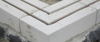
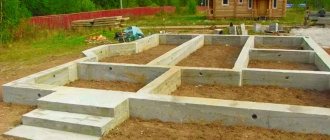
TISE piles
The main disadvantage of the classic pile foundation is that with severe heaving, the support can simply be pushed out. But since the idea itself is very attractive - it can be built quickly with a minimum of costs - on difficult soils they began to make a base at the bottom of the pile - a rectangular reinforced plate. But with this option, the volume of land work immediately increased significantly: for each pile it is necessary to dig a pit larger than the planned base. But the building stands normally even on soils with severe frost heaving.
The pile foundation using TISE technology has a dome-shaped thickening at the base of each support
Under piles made using TISE technology create a similar thickening. But there is no need to dig pits. This extension is formed using a special knife, which is attached to a proprietary drill. This knife forms the extended dome. Further, the entire technology almost exactly repeats the process of constructing a pile or pile-grillage foundation.
Previously, expansions were also practiced, but they tried to do them using micro-explosions or by picking with a blade on a long pole. The main innovation in TISE technology is a drill with an opening adjustable blade. With its help, it is much easier to expand the sole.
How to work with a TISE drill
Advantages and disadvantages
TISE foundations are quickly gaining popularity: with minimal additional costs, a more reliable foundation is obtained. So, its advantages:
- increased resistance to heaving forces;
- the load from the house is transferred to a larger area, which reduces the possibility of uneven subsidence;
- low cost with good characteristics;
- can be designed for houses made of different materials, up to 3 floors in height;
- small amount of land work.
The procedure for making a TISE pile
If a pile or pile-grillage foundation is recommended for your house, it makes sense to make TISE piles. With a small increase in workload, you get a significant increase in reliability. After all, designers do not like pile foundations because it is impossible to find out what kind of soil is under each support. Therefore, it is impossible to predict how reliable and stable the foundation will be. And the TISE foundation has a wider support, which reduces risks. As before, nothing can be predicted, but a large load distribution area is always good.
However, there are also disadvantages. The main thing: the heel of a TISE pile cannot be well reinforced. You can lower the reinforcement cage to the very bottom, but expansion cannot be reinforced. Therefore, there remains the possibility that this thickening will collapse.
TISE piles are the basis of the TISE pile-grillage foundation
There is one more drawback, but this is from the practice of using a drill: it is not easy for them to work. The design itself is interesting. This is not a blade wrapped around a rod, but some kind of container with a composite bottom. Four blades set at an angle are welded on the plates that form the bottom. When you spin the drill, they loosen the soil. Since the bottom is not solid, the soil gets into the body, from where it needs to be removed.
The order of work is as follows: rotate the drill several times around its axis, take it out, and shake out the soil. They lowered it into the hole again, turned it several times, etc. The technology is not complicated, but the work is tedious. The device itself weighs 7-9 kg, plus soil. It needs to be raised and lowered frequently. Overall, it's tiring. Plus, no mechanisms are needed. The downside is that the work is not easy physically. Especially if the soil is rocky or dense clay.
Frost heaving
The phenomenon of frost heaving is characteristic of clay soils, which include:
- sandy loam;
- clay;
- loams.
Heaving occurs when two conditions are present simultaneously: cold and moisture. Clay does not allow liquid to pass through well and accumulates it. In winter, the soil freezes to different depths; for some areas of the country this mark is more than 2 meters.
During frost heaving, the soil increases in volume and pushes out the foundations. The consequences will be uneven deformations, cracks on the walls, and destruction.
The principle of the influence of frost heaving forces on a house
The universal foundation of TISE technology makes it possible to combat this phenomenon. The house on the TISE foundation seems to be caught on the ground. This is possible due to the widening at the bottom. For large buildings they make TISE strip foundations. This technology is a combined option. Here, the work involves both the pillars hooked into the ground and the tape that securely ties the entire structure together.
Where can I use it?
There are no restrictions on the types and materials of buildings: you can make a TISE foundation for wooden, frame, brick and block buildings. Number of storeys - up to three.
The restrictions on soils are the same as when using pile foundations: it is necessary that the piles transfer the load to the soil with normal bearing capacity. To decide whether it is possible or not to use TISE, a geological study of the site in the place where construction is planned is necessary.
What does a TISE pile consist of?
Since the base of the pile is expanded and the resistance to buoyancy forces is greater, this technology can be used on heaving soils. But at the same time you need to consider: there is no point in placing piles closer than 1.5 meters. If placed closer, one extension of the sole will overlap the other. On the other hand, you can’t make a pile larger than 30 cm in diameter either - there is no such drill. If the load-bearing area with such parameters is not enough, you need to use a different type of foundation.
Step by step guide
Since the technology is primarily intended for a wide range of developers who want to independently perform this operation, attention should be paid to the order of work and the requirements for each stage. The main difference from the usual method of foundation installation is the configuration that the TISE pile has
While focusing on the method of obtaining the desired shape, one should not forget about general construction requirements. The order of operations is as follows:
- Soil analysis.
- Marking the territory.
- Installation of beacons horizontally above each pile location point.
- Drilling a well to the required depth.
- Expansion of the hole in the base.
- Removal of soil and control of the completed operation.
- Installation of fittings.
- Filling the hole for the pile with concrete.
- Making the foundation, grillage.
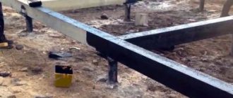
The technology allows you to install piles on any landscape. The construction of a conventional foundation always involves serious excavation work. Leveling the site, removing vegetation. It is not necessary to do this when using TISE technology
When drilling, it is important to maintain a vertical direction. To control the position, you can use a regular plumb line
The smaller the deviation, the more reliable the pile will be. The blade, which carries out the expansion, is brought into its working position using a cord (cable).
The auger mechanism of the soil lifter must be periodically cleaned by lifting the device. The container fills quickly. The rock unloading time is calculated empirically. When the lift is full, the drill does not work. The work will be done in vain.
Features of filling wells with concrete
The structures must be strengthened. The fittings are prepared in advance. The length is calculated in such a way that it is possible to make a high-quality connection with the grillage. In some cases, it is reasonable to produce metal rods with a reserve. This will make it easier to make horizontal level marks, after which the excess is cut off with a grinder. It is not recommended to use cement grades below 400. The proportions of sand and crushed stone are standard, used when mixing mortar for power structures. 1 part cement to 3-4 parts filling.
Making the foundation
Next, they begin to form the binding around the perimeter. There are two options based on the principle of the device.
- Strip foundation - made of ready-made slabs, poured concrete supported on the ground. To do this, a trench is made along the perimeter. A cushion of crushed stone and sand is prepared. Then the formwork is installed into which the concrete mixture is poured.
- The second option is to install an independent load-bearing system mounted on piles. This support structure is called a grillage. With correct calculation and high-quality execution, the load on the piles is distributed evenly. The structure is mounted on a framework along a grillage and has weight restrictions. An excellent option for frame houses and buildings made of SIP panels.
Reviews of the branded drill
The main questions for developers are related to how realistic it is to drill wells manually using a proprietary drill. Looking at the video, it seems that this task is not easy. But here are some reviews.
The soil on my site is different: some are loam, some are dense clay, and such that you can only chop them with an axe. At first I thought about renting a motor drill, but I decided to try it straight away with a drill. And nothing, not very hard. As a result, I decided that a motor drill would not speed up the process much, so I made all 40 pieces by hand. During the day, 5-6 2-meter wells were produced. They drilled easily, but with expansion it was difficult: I already had dense soil there, and it was difficult to turn with the blade open.
Oleg, Kharkov
I modified the TISE drill I bought: I welded additional teeth, instead of a rope that opens the blade, I adapted a rod - now you can put pressure on it, and not just pull. And most importantly, I lengthened the handle so that two people could turn it. While they were drilling the extensions, they twisted it 90°, but the work became much easier. In general, I'm pleased.
Nikolay, Krasnoyarsk
Working mixture
A cement-sand mortar with a small amount of water (the so-called hard sand-cement mixture) is used as a working mixture for molding wall blocks. The mixture is prepared in portions designed to produce 10 - 12 blocks (0.8 -1 square meter of wall), by hand kneading. The properties of the rigid sand-cement mixture are strength and frost resistance, high vapor permeability. Such a wall “breathes,” which made it possible to add the letter “E” to the name of the technology - ecology.
TISE technology. The principle of using adjustable formwork
For grade 400 cement, the volume ratio of sand: cement: water is 3:1:0.5; for cement grade 500 - 4:1:0.5. Material consumption per 1 sq. meter of wall is: with a wall thickness of 25 cm - 50 kg of cement (grade 400) and 0.12 cubic meters of sand, with a wall thickness of 38 cm - 75 kg of cement and 0.18 cubic meters of sand.
| Laying the mixture | Consolidation of the mixture | Alignment |
Calculation of the TISE foundation
The calculation method is no different from the calculation in the general case. The load from the house is calculated and then compared with the total load-bearing capacity of the planned number and diameter of piles.
First, place the piles on the house plan. They must be in the corners and at the junctions of the walls. If the distance between the piles is more than 3 meters, intermediate ones are placed between them. So you place all the supports on the plan, adhering to the rule:
- minimum distance - 1.5 meters;
- maximum 3 m.
Then calculate the load from the house. To do this, you first need to calculate the weight of the house (all building materials + furniture, plumbing, heavy household appliances).
Average loads from different types of house components
Speaking on average, for buildings made of brick or shell rock, 2400 kg can be taken for each square of area, for light building blocks (foam concrete, aerated concrete, etc.) - 2000 kg, for wood and frames - 1800 kg. These average standards can be used as a preliminary guide. If you decide to take everything seriously, you will need to follow the entire methodology: counting materials of walls, ceilings, roofing, finishing, etc. Since the technologies and materials used may be different, the discrepancies can also be significant.
We multiply the resulting value by a correction factor - 1.3 or 1.4. This is a safety margin. The resulting figure is the load that will need to be transferred through the piles.
Now, using the table, you select what diameter the pile should have so that it can transfer the required weight.
Load-bearing capacity of piles of different diameters in different soils
If the planned number of columns with an expansion of the selected diameter can transfer the required load, you do not need to redo anything. If the transferred mass is too small, it is necessary to either increase the number of piles or make a “heel” of a larger diameter.
Purchase of materials for piles.
I called the nearest concrete plants. I wanted to buy the best ingredients for concrete, but later it turned out that not everything was so simple.
At the first plant they told me that they would not bring me sand, or crushed stone. Or rather, of course they can, but with a scow of 30 m3. But I learned everything about their concrete.
The weekend passed to no avail and I thought that if I continue to slow down like this, it will take a long time to build. In the morning of the next weekend, I called another place and agreed that in an hour they would bring me both sifted sand and crushed granite stone, fraction 5–20, 10 cubic meters each.
I had barely reached the site when the driver called and brought crushed stone. I unloaded it at the indicated place without any problems and left for sand. The crushed stone is excellent, not like my previous one with a lot of dust and poor geometry (very flaky).
The new crushed stone also has a geometry close to a cubic shape.
With sand it was much worse. The sand is heavier and the Kamaz got stuck tightly, resting against a pile of rubble. Why the hell the driver drove there in the first place is not clear. I had to unload it right there. They put a plastic film over the sand to separate it from the rubble and the driver unloaded the body.
The empty truck somehow managed to crawl out of the formed rut and crawled away.
I don’t know where the driver got this sand. The manager assured me that they make it into concrete and sifted sand. I don’t know what they sifted it through, but the sand turned out to be unsifted and contained many stones up to the size of an orange.
I did my sand analysis. That is, I collected half a liter jar of sand. Filled it to the top with water. Shake and leave for 15 minutes. The contents of the jar were clearly divided into factions.
Next, take a ruler and measure the thickness of the layers. Then we convert it to percentages. The analysis is of course very approximate, but it gives an idea of the sand. My sand turned out to be about 4-6% clay (depending on the sample location).
Not good for good concrete. I'll sift through it. The result should be normal sand, as otherwise it is good. Quite large. There is extra work ahead, but it’s his own fault. They didn’t promise me pure sand (without any admixture of clay at all), but the fact that it wasn’t sown was a mistake, I bought it without documents.
Next came the purchase of fittings. This is where I went nuts. I ordered reinforcement mesh and six-meter reinforcement of different diameters immediately for the piles, grillage and basement ceiling. And also 48 meters of strip on the fence so that the mesh does not sag, although it did not sag anyway, contrary to everyone’s predictions.
It turned out to be about three tons. I was crazy about unloading it, the driver helped me well. Leaving the reinforcement and mesh, haphazardly, we said goodbye. Then I spent another three hours laying it all out in even stacks, dividing the reinforcement by diameter.
For the next weekend I decided to buy 20 bags of M500d0 cement to start with, roofing felt and small items.
It rained on Saturday and rained on Sunday morning, then it was wet for the truck and a little late for the order. I didn’t want to wet the cement and the plans had to be reconsidered. I need to go on vacation.
TISE foundation: work order
The TISE technique itself has some recommendations:
- The piles should be buried approximately 20 cm below the freezing level for the region.
- To reinforce the pile, four rods of ribbed reinforcement with a diameter of 10-12 mm are used. The rods should be placed no closer than 4 cm from the edge.
- If the slope of the site is more than 10%, the release of the reinforcement must be connected to the grillage.
- Use either a high grillage - raised 150 mm above the ground, or make a pile-strip foundation with a shallowly buried strip. The second option is used for heavy buildings, the weight of which cannot be transferred through piles; then a tape is made that increases the transfer area.
Scheme of reinforcement of a pile-grillage foundation with a reinforced concrete grillage (pile-strip) - You should not make sand bedding at the bottom of the well: it will not have normal density and will not work.
- To ensure reliable support, use concrete vibrators. Manual vibration using a rebar is ineffective. If your farm does not have such a device, rent it while the foundation is being poured: the strength increases significantly.
- The formwork for the pile is made from roofing felt, roofing felt or glassine rolled into a tube. It is better that it has several layers (2-3). There is no need to fasten them with anything: they twisted them slightly smaller than the diameter and inserted them. The height of this formwork is 15 cm above the ground level, regardless of whether there is a slope on the site or not. It is advisable to sprinkle this protruding piece with sand or soil and compact it around it. This will prevent the roofing paper from falling apart when pouring concrete.
TISE foundation is a subtype of pile-grillage foundation. And the technology for its production is no different. The whole difference is in the drilling process. No others. The work procedure and technology for manufacturing a pile-rosvet foundation are described here. And in this article we’ll better give some practical advice.
Difficulties during drilling
If the soil is very loose - fine sand - the walls of the well may crumble. To prevent this from happening, add water. The sand will compact and hold its shape. Water will also help if the soil is very dry and dense. After drilling a few tens of centimeters, fill the well with water. It will soften the soil, it can be chopped with a shovel or other device, and then removed with a drill.
Drilling wells for the TISE foundation with your own hands is not easy, but it is possible even alone
Difficulties are created by the powerful roots of trees and bushes. They need to be chopped. To do this, the ax handle is welded (attached) to the handle. By sharply lowering it into the hole, the roots are crushed.
How to create an extension
After reaching the design depth of the well, a plow is attached to the drill. It can be fixed in two positions: to form a heel of 50 or 60 cm. The plow is tied to a rope.
This is a plow that forms a dome-shaped extension
You lower the drill down, the rope is taut, the plow is pressed. The rope is released, and he falls down under his own weight. You start to rotate (it’s hard - the cutting surface is large), the blade cuts the soil, forming a thickening.
You can rotate both clockwise and counterclockwise. If clockwise, then try not to press down: there is no need to go deeper. When rotating counterclockwise, only the soil is cut without deepening, but another problem arises: the soil is poured under the drill, pushing it upward.
The optimal order of work is as follows: scroll counterclockwise several times. As soon as you feel that the blade has rested against the arch, make a few turns clockwise, collecting cut soil into the drill body. Take out the drill and pour out the soil. Repeat several times until an extension is formed (the soil stops building up).
On hard soils, working with the plow open can be problematic. Then you can create the expansion in stages. First set the plow to the smallest distance, then increase it to the desired size.
Filling with concrete
If the groundwater level is low, no problems arise: fill it in and treat it with a vibrator. All.
If the groundwater level is high, the heel can be filled immediately after it has been formed. You will only need to insert the reinforcement. Then you knit it before drilling begins. Filling the main part of the well can be left “for later”.
Having placed the reinforcement and formwork, they begin to pour concrete
If there is a lot of water and it comes quickly, you will need a large bag made of thick film with a hole at the bottom. You insert it into the well and pour concrete. Because it is denser, it displaces water. Having filled the heel, pull out the bag. It will be useful for the next piles.
The video below demonstrates the technology of building a foundation with TISE piles and a high grillage.
Manufacturing of tape circuit
When pouring the grillage, remember that it must be a strong concrete structure, reliably reinforced around the perimeter
Pay attention to the quality of the mixture and the reliability of the reinforcement connections. Sequence of events:
- install and level wooden panels;
- cover the inner surface with plastic wrap;
- install reinforcement cages, connecting them with wire into a rigid contour;
- fix the immobility of the formwork using steel pins and transversely located bars;
- fill the prepared circuit with concrete mortar, remove air from the mass;
- Allow the concrete mixture to harden for 4 weeks.
Molding of wall blocks
The prepared rigid mixture is placed in a mold with inserts installed - void formers and compacted with a manual tamper. Excess mixture is removed with a scraper under the upper level of the liners. Stripping is carried out immediately after compaction. Small projections at the bottom of the mold span the bottom row of blocks, preventing movement. However, after 4-5 rows it is still better to check the vertical with a plumb line and lay down the reinforcing mesh.
Reinforcement with flexible connections with a diameter of 6 mm from basalt fibers; they are laid in each wall block when it is formed.
The complete molding cycle of one block takes 5 - 7 minutes. Thus, with one formwork, up to 80-100 blocks can be formed per day. Of course, it’s more convenient to work with two or three people: one kneads, the other brings the mixture, the third forms the blocks, and the work goes smoothly. If the wall is rubbed down at the end of the working day, it will not require plastering: you can immediately putty and paint. And this is a significant saving of labor and money.
| Two walls and flexible connections form a rigid and stable structure | Penoizol provides insulation like 3 meters of brickwork |
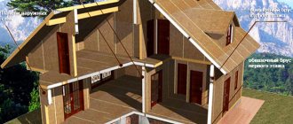
Installation of windows and doors
The window block is secured in the window opening with metal plates screwed to the window frame. For one window, six plates are enough - two on each side and each top side of the frame (Fig. 12).
Before installing the window, the insulation along the lower edge of the opening is covered with a panel of moisture-resistant plasterboard or a board treated with a septic tank. Additionally, transverse slats are laid on the lower surface of the opening, on which the window block and window sill will rest. The thickness of the slats is selected based on the intended depth of the frame in the upper “quarter”. The side and top window slopes are made of moisture-resistant plasterboard 12 mm thick. Before installation, the slopes are preliminarily adjusted to the location, and pressure boards 50 mm thick and spacer boards are made to ensure tight and reliable fixation of the slopes. To avoid deformation of the frame of the window unit, the window sashes must be closed before installing the slopes. Installation begins from the side slopes. To do this, polyurethane foam is squeezed out along the back and front edges of the drywall and pressure and spacer boards are immediately installed. In this position, the swelling foam fills the entire free volume under the drywall (Fig. 13). The next day, the pressure boards can be removed. The slope angle is edged with a plastic or metal plaster corner.
Such window (door) slopes are neat, durable and cheap. In addition, they have good thermal insulation properties. The window sill is placed under the ledge of the frame, laid on the slats and secured with foam, not forgetting to install the pressure and spacer boards. If the cavity under the window sill is used to organize supply ventilation, then from the outside, under the drip panel, the gap is closed with a fiber filter, for example, a padding polyester roller. From the side of the room, the ventilation gap is covered with a flap or connected to a duct connected to the heating system (Fig. 14).
Strengthening a three-layer wall
The resistance of a truss structure to compressive loads depends on the rigidity of the concrete walls and the stability of the flexible connections. Sometimes you have to resort to strengthening the truss of a three-layer wall. The need for this may arise in the following cases: - if the distance between the floors is more than 5 m; - if the wall is subject to lateral forces (soil pressure on the basement walls or loads during seismic vibrations); - with heavy loads on both sides of window or door openings more than 2 m wide.
Increasing the rigidity of the truss component of a three-layer wall comes down to increasing the diameter of the flexible connections. When replacing Ø6 mm ties with Ø8 mm ties, the stability of the wall increases more than three times (Figure 5a). Another option for strengthening the wall is to introduce an additional horizontal flexible connection. It is placed between the void formers before laying the mixture (Fig. 56). In this option, the stability of the wall increases almost 2.5 times, but twice as many flexible connections will need to be installed in this place. Other similar options for increasing the stability of a three-layer wall come down to giving the latter some curvature or introducing a vertical angle. The construction of concrete floors is known to also increase the stability of walls, which is widely used in construction in seismically active regions.
Ventilation
So, “breathing” walls are built with internal cavities-wells and horizontal technological holes with a diameter of 1 cm, which were formed during stripping. It would be a sin not to take advantage of this.
The creators of the TISE technology provided a ventilation system and called it a “stone hut”. A displacement ventilation system is formed “by itself” during the construction process; you just need to provide ventilation ducts in the exterior and interior of the house. Supply ventilation is provided by a system of wells, ventilation ducts and technological openings in the external walls of the house. Exhaust ventilation is organized using traditional methods. The best option is to install exhaust ventilation windows in each room, located under the ceiling opposite the main supply ventilation flow and equipped with adjustable blinds. Now the flow of fresh air can be controlled!
These articles may also be of interest to you:
- Installation of facade blocks
- Features of external wall insulation
- Original small kitchen design
- Crane seat repair
Bandaging oblique angles
Often, due to the architectural features of the house, corner dressings of the walls are made at an indirect angle, for example, on bay windows. The technology for constructing a three-layer wall on such a site must be associated with a specific project and taking into account the available materials.
Relatively short bay window walls can be made without ligating the wall blocks, but with the introduction of additional horizontal flexible connections and with more frequent horizontal reinforcement of the wall. To better connect the blocks, vertical grooves are cut at their ends using the corner of the TISE formwork (Fig. 4a). The corner gap between adjacent blocks is filled using homemade formwork one or two blocks high. External corner formwork can be easily made from 1 mm thick sheet metal, boards or plywood. Please note that the formwork in this case should not be too bulky and heavy - after all, it will have to be pressed into place manually. The formwork for the inside of the wall does not have to be made at an angle; a simplified form is suitable here. To compact the mixture in the corner gap, make a narrow wooden tamper. Before laying the mixture, place a horizontal flexible connection down on the previously formed row of wall blocks. The process of filling the mold with a hard mixture will not cause problems. However, this operation is best performed by two people: one holds the formwork, and the second fills and compacts the sand-concrete mixture. Having filled the gap with the mixture, the corner formwork is moved down along the corner, preventing it from adhering to the mixture. After grouting the corner, the surface of the bay window will be fairly smooth. Short bay window walls can also be laid out from standard bricks, without resorting to TISE formwork. One of the developers for the corner of the bay window with TISE-2 formwork molded the blocks separately, on a flat area, and sawed off the corners with a hacksaw that had served its useful life. His sand-cement mixture did not contain stones, and he sawed the block quite easily the next day. With this method, the blocks had to be laid on the mortar in the traditional way. By the way, the TISE-2 formwork allows you to mold two blocks at a time with dimensions of 510x115x210 mm outside the masonry, which can be used as a building material (Fig. 4b).
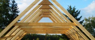
Connecting walls to roof frame
Fastening a mauerlat - the supporting beam of the roof frame - to a three-layer wall is not very different from the traditional approach taken in construction. As an example, here is a solution that I have implemented in several projects. I made the Mauerlat from two 15x5 cm boards, fixed to the surface of three-layer walls using metal dowels 08... 10 mm with a hexagonal head (Fig. 17). The average step for installing fasteners is 26 cm. I attached the roof rafters to the Mauerlat with 5x120 mm nails.
Concrete structure care
Caring for a concrete structure is necessary to minimize plastic shrinkage of the material, provide protection against premature drying and destruction of structural bonds due to sudden changes in temperature.
To do this, create a moistened compress of sawdust on the surface of the concrete solution and cover it with a film on top . Once every three days, the protective layer is watered with water from a watering can (drip irrigation) and re-covered with polyethylene.
Winter maintenance of concrete involves forced heating using mineral wool or polystyrene foam. Sometimes, for this purpose, antifreeze modifiers are added to the solution when mixing.
After the concrete has gained the necessary strength, construction of the grillage begins using standard technology for a pile foundation with reinforced concrete strip.