A dacha today is no longer a summer building with amenities in the yard, but actually a full-fledged suburban home. Moreover, it is equipped with powerful modern appliances - a refrigerator, a washing machine, a microwave oven. All these mechanisms make housework easier, but they are also objects of increased danger. In order to avoid fires and tragic accidents, it is recommended to equip grounding at the dacha with your own hands. The circuit diagram is not so complicated, and it is not necessary to invite specialists for installation.
Do-it-yourself installation of a grounding loop in a dacha
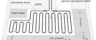
The most common grounding system is a structure of three metal pins (electrodes). The rods are buried in the ground and welded together with a horizontal steel strip. The finished grounding loop is connected to the power panel using a steel rod laid underground.
Elements of the grounding system at a summer cottage
Grounding of PUE pipelines: let's look at the points
In the process of laying pipelines for any purpose, it is necessary to take care of the safety of their operation. It is important to prevent the negative impact of a strong electrical discharge on both the pipeline itself and the substances transported through it. Especially for this it is important to install grounding.
Basic Rules
The document regulating the methods of implementation and installation of grounding systems is the “Rules for the Construction of Electrical Installations” (PUE). It states that grounding process pipelines is a mandatory condition for their admission to operation.
Basic rules when implementing such systems:
- A continuous metal connection must be ensured along the entire length of the pipeline, regardless of its design and purpose.
- The type of grounding loop must correspond to the resistivity of the soil at the installation site and the spreading current of the structure.
- The pipeline must be connected to the grounding circuit at least at two points.
The requirements for protection from indirect contact apply to:
1) housings of electrical machines, transformers, devices, lamps, etc.;
2) drives of electrical devices;
3) frames of distribution boards, control panels, panels and cabinets, as well as removable or opening parts, if the latter are equipped with electrical equipment with a voltage higher than 50 V AC or 120 V DC (in cases provided for by the relevant chapters of the PUE - higher than 25 V AC or 60 V VDC);
4) metal structures of switchgears, cable structures, cable couplings, shells and armor of control and power cables, sheaths of wires, sleeves and pipes of electrical wiring, shells and supporting structures of busbars (conductors), trays, boxes, strings, cables and strips on which reinforced cables and wires (except for strings, cables and strips along which cables with a neutralized or grounded metal sheath or armor are laid), as well as other metal structures on which electrical equipment is installed;
5) metal shells and armor of control and power cables and wires for voltages not exceeding those specified in 1.7.53, laid on common metal structures, including in common pipes, boxes, trays, etc., with cables and wires on higher voltages;
6) metal cases of mobile and portable electrical receivers;
7) electrical equipment installed on moving parts of machines, machines and mechanisms.
When automatic power shutdown is used as a protective measure, the specified exposed conductive parts must be connected to the solidly grounded neutral of the power source in the system and grounded in systems and.
It is not necessary to intentionally connect to the source neutral in the system and ground in systems and:
1) housings of electrical equipment and devices installed on metal bases: structures, switchgears, switchboards, cabinets, frames of machines, machines and mechanisms connected to the neutral of the power source or grounded, while ensuring reliable electrical contact of these housings with the bases;
2) structures listed in 1.7.76, while ensuring reliable electrical contact between these structures and the electrical equipment installed on them, connected to the protective conductor;
3) removable or opening parts of the metal frames of switchgear chambers, cabinets, fences, etc., if electrical equipment is not installed on the removable (opening) parts or if the voltage of the installed electrical equipment does not exceed the values specified in 1.7.53;
4) reinforcement of insulators of overhead power lines and fasteners attached to it;
5) open conductive parts of electrical equipment with double insulation;
6) metal staples, fasteners, sections of pipes for mechanical protection of cables in places where they pass through walls and ceilings and other similar parts of electrical wiring with an area of up to 100 cm, including broach and branch boxes of hidden electrical wiring.
When performing automatic power off in electrical installations with voltages up to 1 kV, all exposed conductive parts must be connected to a solidly grounded neutral of the power source if a TN system is used, and grounded if an IT or TT system is used. In this case, the characteristics of the protective devices and the parameters of the protective conductors must be coordinated to ensure the normalized time for disconnecting the damaged circuit by the protective switching device in accordance with the rated phase voltage of the supply network.
In electrical installations in which automatic power off is used as a protective measure, potential equalization must be performed.
To automatically turn off the power, protective switching devices that respond to overcurrents or differential current can be used.
Selecting a ground electrode
To manufacture the system, steel rods or pieces of reinforcement can be used. PUE standards allow the use of home-made structures or factory-made kits. Paintwork or a layer of preservative that impairs the transmission of electric current is not allowed on the surface of the elements. Screw connections can be coated with a layer of special mastic, which prevents corrosion and does not interfere with the passage of current. The table shows the values of sections and wall thicknesses for profiles used in assembling the grounding system.
| Type of material | Pin diameter for vertical or horizontal position, mm | Cross-sectional area, mm² | Wall thickness, mm |
| Carbon steel | 16 and 10 respectively for a solid bar and 32 for a pipe | 100 (for rectangular and corner profiles) | 4 for shaped profile and 3.5 for pipe |
| Galvanized metal | 12 and 10 respectively for a solid bar and 25 for a pipe | 75 for rectangular profile | 3 for rectangular profile and 2 mm for tube |
| Copper | 12 for a rod and 20 for a pipe, it is allowed to use a braided cable with a wire diameter of at least 1.8 | 50 for rectangular profile and 35 for multi-core cable | 2 regardless of assortment |
Material of manufacture
For production use:
- Profiles made of carbon steel, characterized by low corrosion resistance (no more than 15 years). Copper coating or galvanizing increases the service life by 2 times.
- Stainless steel components that can withstand groundwater exposure for 75–100 years. The disadvantage is the high price and complexity of joining parts (arc welding of stainless steel requires special equipment and a highly qualified welder).
- Copper. The metal is not used in its pure form due to its high price and low mechanical strength.
Pipe stands
To install an entry device in a commercial building or country house, you must use a pipe stand.
Its main task is to fix the power wire that leads to the shield, as well as install the shield itself. According to the requirements of the PUE rules, the pipe stand requires mandatory grounding.
Not far from the shield, you need to drill a hole through which it is important to place a grounding bolt. Both the pipe stand itself and the shield require high-quality grounding. A metal corner one and a half meters long should be driven in not far from the rack. Next comes the connection of the pipe stand, shield and corner.
The zero bus is also protected. The neutral wire marked SIP4, which comes from the support, must be connected to it. To perform the operation, you need to use the yellow-green wire marked PV-3, on which the tips are installed. At this point, the grounding of the metal pipe stand can be considered complete.
Is it possible?
Before we consider technological schemes and answer the question “how to get electricity from the soil?”, Let’s figure out how realistic this is.
It is believed that there is a lot of energy in the earth and if you make an installation, you will forever use it for free. This is not true, because in order to receive energy you need a certain piece of land and metal pins that you install in it. But the pins will oxidize and sooner or later the energy intake will end. In addition, its quantity depends on the composition and quality of the soil itself.
To achieve good power you need a very large area of land, so in most cases the energy obtained from the ground is enough to turn on a couple of LEDs or a small light bulb.
It follows from this that it is possible to obtain energy from the earth, but it is unlikely to be used as an alternative to power grids.
PUE rules
The arrangement process is regulated by the PUE standards. According to them, grounding of process pipelines is mandatory. Only in this case is their use allowed.
System requirements:
- Correspondence of the type of circuit to the spreading current of the structure, as well as the resistivity of the soil at the installation points.
- A continuous electrical chain that is created along the entire length of the route. In this case, the purpose and design of communications are not important.
- Mandatory connection of the structure and the grounding loop at least at 2 points.
- All types of communications at points of entry into the structure must be grounded. Therefore, grounding heating pipelines in residential buildings is also mandatory. Especially if the pipes are made of metal.
Rating of the best industrial kits
Factory-produced kits are easy to assemble. The owner of a house or warehouse can install the circuit himself. Installation requires a minimum of preparatory work. The components are placed in cardboard containers, which simplifies the transportation process and protects the parts from damage. The components are made of steel rod coated with copper, which ensures increased service life.
The ends of the pins are threaded, and the kits come with special tips that make it easier to drive the rods into dense soil.
Zandz ZZ–000–045
The Russian-made module consists of prefabricated electrodes with a length of 5 to 15 m (depending on the number of elements). The kit is used for grounding residential or office buildings and provides protection against lightning. Supplied as a kit containing threaded couplings for assembling electrodes from blanks. The surface of the steel pins is covered with a layer of copper; attachments for a jackhammer are provided (necessary during installation work). The average price of a set is 70 thousand rubles.
Galmar GL–00045
The set includes 30 metal pins 1.5 m long and connecting threaded elements. The surface of the electrodes is coated with copper, which provides resistance to corrosion. There are clamps for connecting conductors, starting tips for electrodes and attachments for a jackhammer, allowing you to quickly bury the pins in the ground.
The components are supplied as a set, packed in a box made of thick waterproof cardboard. The average cost of a set is 70 thousand rubles.
Ezetek CN-6
The budget set includes an electrode made of stainless steel and having a length of 6 m. A carbide tip is provided, which simplifies the procedure for installing the pin in the ground. The electrode is assembled from 1.5-meter elements; threaded bushings are used for connection. There is a tube with a special paste that conducts electric current. The kit is designed for use in private homes or country houses; installation is carried out using a hammer drill or sledgehammer. The price of a grounding system starts from 12 thousand rubles.
How to perform anodic grounding of pipelines?
The design of protection systems directly depends on operating conditions.
If communications run inside the structure, then they are connected to the natural grounding of the house, as well as artificial grounding loops.
The technology is also used for other technological equipment. For example, for pipe stands, which are used for aerial laying of electrical wires and serve as supporting devices.
If the main pipeline is grounded, then an artificial circuit is installed along its route.
The grounding cable is attached to the pipe using a metal clamp. It is equipped with a special connection for fastening. At the attachment points, the surface of the pipes is cleaned. This ensures better contact between the components.
Recommended cable cross-section:
- from 2.5 m2 (copper, providing mechanical protection);
- 4 m2 or more (copper, without mechanical protection);
- over 16m2 (made of aluminum).
Required loop resistance (maximum values):
- 1-phase current networks – 5/10/20 Ohm, in case of voltage indicators (linear) 380/220/127 V;
- 3-phase networks – 5/10/20 Ohm, with line voltage indicators 660/380/220 V.
Effect of insulation
The insulation resistivity indicator can significantly influence the characteristic features of the pipeline. According to studies, the level of resistance in the grounding of a pipeline using bitumen insulation can greatly depend on the potential difference between the soil and the pipeline itself.
If the difference varies within a few hundred volts, glow discharge may occur at defective locations, which in turn reduces the ground resistance. If the potential difference is one kilovolt or more, an arc discharge appears between the soil and the pipeline.
It, accordingly, greatly reduces the resistance of the installed grounding. Portable grounding can also be used, in which the clamp is the main part.
Grounding flange connections
Continuity of the electrical circuit is a prerequisite for pipeline safety. Therefore, the flanges are grounded. It is implemented by installing jumpers made of copper wire and connecting flange or other connections.
It is recommended to use copper wire, brand PuGV or PV3. By pressing, tips are installed on the ends of the wire. Next, they are attached to the pipe using bolts.
Explosive areas
Taking into account the design and purpose, we can distinguish:
- oil pipelines and gas pipelines;
- systems through which alcohol-containing liquids/gases are transported.
Transportation of explosive and fire hazardous substances imposes increased safety requirements. The standards are described in the PUE (chapter 7.3).
In the case of explosive premises, the use of natural grounding conductors is permissible only if they provide additional protection. The main one should be an artificially constructed circuit.
Aggressive soils and protection of reinforced concrete from their effects
Currently, issues of protecting reinforced concrete structures from the aggressive influence of soils are regulated in Russia by the interstate standard GOST 31384-2008 “Protection of concrete and reinforced concrete structures from corrosion. General requirements". According to this GOST, the aggressiveness of the soil is determined by the depth to which concrete collapses or loses its protective properties relative to steel reinforcement over 50 years. Weak degree of aggressiveness - less than 10 cm, medium - from 10 cm to 20 cm, high - more than 20 cm.
Primary methods of protection include changes in the composition of concrete, as well as a set of design and engineering solutions that reduce the level of corrosion. The concrete must be denser, providing better protection for the steel reinforcement than usual. Secondary measures include applying protective coatings to reinforced concrete structures, as well as treating them with an antiseptic if the cause of corrosion is the action of bacteria.
LLC Svoy Master & PoliStyle
February 07, 2020
PUE in questions and answers. Grounding
Grounding devices for electrical installations with voltages up to 1 kV in networks with a solidly grounded neutral
Where should the grounding conductor be connected if a CT is installed in the PEN conductor connecting the neutral of the transformer or generator to the PEN bus of the switchgear up to I kV?
Answer. It should not be connected directly to the neutral of the transformer or generator, but to the PEN conductor, if possible directly to the CT. In this case, the division of the PEN conductor into RE and N conductors in the TN-S system must also be carried out behind the CT. The CT should be placed as close as possible to the neutral terminal of the transformer or generator.
What should be the resistance of the grounding device to which the neutrals of a generator or transformer, or the terminals of a single-phase current source are connected?
Answer. There should be no more than 2, 4 and 8 Ohms at any time of the year, respectively, at 660, 380 and 220 V three-phase current source or 380, 220 and 127 V single-phase current source. This resistance must be ensured taking into account the use of natural grounding conductors, as well as re-grounding conductors of PEN or PE conductors of overhead lines up to 1 kV with a number of outgoing lines of at least two.
What should be the resistance of the ground electrode located in close proximity to the neutral of a generator or transformer, or the output of a single-phase current source?
Answer. There should be no more than 15, 30 and 60 Ohms, respectively, at line voltages of 660, 380 and 220 V of a three-phase current source or 380, 220 and 127 V of a single-phase current source. If the earth resistivity is ρ > 100 Ohm×m, it is allowed to increase the specified standards by 0.01 ρ times, but not more than tenfold.
At what points in the network should the PEN conductor be re-grounded?
Answer. Must be performed at the ends of overhead lines or branches from them with a length of more than 200 m, as well as at the inputs of overhead lines to electrical installations in which automatic power off is used as a protective measure in case of indirect contact.
What should be the total resistance to spreading of grounding conductors (including natural ones) of all repeated groundings of the PEN conductor of each overhead line at any time of the year?
Answer. There should be no more than 5, 10 and 20 Ohms, respectively, at line voltages of 660, 380 and 220 V of a three-phase current source or 380, 220 and 127 V of a single-phase current source. In this case, the spreading resistance of the grounding conductor of each of the repeated groundings should be no more than 15, 30 and 60 Ohms, respectively, at the same voltages. If the earth resistivity is ρ > 100 Ohm×m, it is allowed to increase the specified standards by 0.01ρ times, but not more than tenfold.
Installation rules
Attention! All connections of the grounding system are made only by welding, where two elements or sections are overlapped. The quality of such a connection will be checked by hitting a kilogram hammer. Welded joints must be treated with bitumen-based varnish.
Now, regarding the wiring of grounding conductors. They can be carried out on concrete and brick structures, both in the horizontal and vertical planes. Fastening to structures is done with dowels, between which you can leave a distance:
- on straight sections in the range of 600-1000 mm;
- on bends and turns no more than 100 mm.
The distance from the floor base to the fastening point should be 400-600 mm. If the grounding system of conductors will be laid in wet rooms, then under them it will be necessary to lay pads with a thickness of at least 10 mm.
Grounding PUE - standards, protective measures
The use of electrical appliances is an integral part of every person’s life.
During their use there is a risk of electric shock. Therefore, a protective grounding system was created. In order for this system to operate effectively and fulfill its protective functions, the requirements for the protective device were formulated. Such requirements are contained in the rules for electrical installations (PUE). The grounding PUE section will include basic recommendations: how to properly implement a grounding loop; how to install protective structures for the electrical network; grounding standards; grounding resistance and others. These rules make it possible to create conditions for the effective protection of premises of various modifications from negative impacts.
Standards of PUE grounding
Grounding PUE standards are a set of regulatory legal acts. These rules include recommendations on how to carry out electrical wiring correctly, a description of various electrical installations and the principle of their operation, as well as the requirements for electrical systems and their components.
Grounding installation work must be carried out in accordance with the electrical installation regulations. The criteria defined in the PUE will allow all connections to be made without errors, maintaining all standards. This guarantees reliable operation of the protective system in the house and will avoid the negative consequences of natural and man-made impacts.
If you unquestioningly follow all the rules described in the PUE, this will lead to large financial costs, so electricians and engineers follow only very important recommendations in their activities.
In accordance with the rules of the PUE, a repeated protective circuit must certainly be located at the exit areas from the premises. It is recommended to install natural grounding electrodes at this location. These include reinforced concrete devices, large metal parts, which for the most part are directly connected to the ground.
The PUE also specifies items that cannot be used as grounding conductors: energized metal objects, sewer and heating pipes, as well as pipelines with flammable substances.
When installing grounding, it is necessary to carefully carry out calculations, taking into account all the factors affecting the quality of the device being created, and it is necessary to follow the PUE.
Work order
It is best to entrust the work to specialists, but if you have a strong desire to do everything yourself, then this is quite possible.
System elements
The main elements of the grounding system are:
- grounding conductors - taps that are immersed in the ground to drain stray current;
- connecting material - elements that are used to connect grounding conductors into a single structure. These can be wire, strip or corner;
- grounding bars, which are made of electrical bronze. Such buses connect all conductors;
- various fasteners.
Grounding depth
The standard grounding system is designed for the taps to be driven to a depth of about 3 meters. Some schemes require deeper placement of pins (in such cases the depth is 6 meters).
Did you know? Oxford University has an electric bell that has been in operation since 1840. The elements that feed it are filled with sulfur for tightness, so no one knows exactly how they are constructed.
If the density of the soil does not allow placing bends at the required depth, then their number is increased until the required resistance is obtained.
Installation process
The first step is to determine the location of the circuit. The ideal option would be if the circuit is placed at a distance of 10 meters from the power shield.
Now you can begin work, which should be divided into the following stages:
Dig a pit in the shape of an isosceles triangle. The pit should be similar to a strip foundation, with the distance between the rods being at least 1 meter, the width - about half a meter and the depth - about 1 meter.
Next, you should dig a ditch that will go from one corner of the triangle to the power shield. At the next stage, you need to immerse the pins into the ground, which need to be placed at the vertices of the triangle
In some cases it is necessary to drill the ground (if the soil is dense). Important! Long electrodes can be replaced with shorter pins, but their number should be increased. In this case, the properties and efficiency of the grounding system will be the same
The rods must be driven into the ground so that they are visible above the surface of the ground. This is necessary so that the electrodes can be connected to each other by a bus. The cavity around the electrodes can be filled with soil mixed with salt, this will help reduce the resistance of the electrodes, but at the same time speed up the process of metal corrosion.
Next, you need to weld the harness to the electrodes so that a triangle is formed.
After this, you need to run a strip along the trench to the distribution panel.
Next, you should attach the conductor to the shield using a pre-welded bolt. Don't forget about checking. It is imperative to check the resistance using an ohmmeter. A safe value is 4 ohms. If this indicator is obtained, then you can fill the trench. If the indicator is more than 4 ohms, you need to drive in a few more taps to get the required resistance.
Video: how to make grounding yourself
In the end, I would like to say that installing a grounding system with your own hands is quite simple.
The main thing is to follow safety precautions and safety precautions when working with power tools.
Grounding resistance PUE
According to the PUE standards, all electrical appliances are manufactured in accordance with the standardized values:
- for telecommunications equipment, the protective device must have a resistance of no more than 2 Ohms or 4 Ohms;
- for reliable operation of a substation with a voltage of 110 kV, this indicator should be no more than 0.5 Ohm;
- when the power line voltage is 220V single-phase current source and 380V three-phase current, the resistance of the transformer substation must correspond to a value of no more than 4 Ohms;
- protective structures of overhead communication lines are connected to grounding with a resistance of no more than 2 ohms;
- when connecting lightning rods, the protective device must correspond to a resistance of no more than 10 Ohms;
- for private sector housing when operating the TN-CS system, a local grounding device with a resistance of no more than 30 Ohms is recommended;
- To connect private houses to a 220V/380V electrical circuit when operating the TT system using a residual current device, a protective grounding device with a resistance of no more than 500 Ohms is required.
Classification of fittings
Smooth reinforcement is a round steel rod with a flat surface and a certain strength class: A1 or A240. Unlike smooth reinforcement, corrugated reinforcement has a wavy surface with periodically repeating corrugations, as well as varying strength (A2, A3, A4, A5, A6). Class A1 reinforcement is used to create a single frame, which is why smooth reinforcement is called assembly reinforcement. Corrugated reinforcement is used in places where there will be tension and heavy loads, for example, when laying a foundation. The cross-sectional diameter of corrugated reinforcement is larger than the diameter of smooth reinforcement. In general, the main characteristics of any reinforcement are strength, reliability, and corrosion resistance.
It is impossible to build any structure without reinforcement, because it plays the same role as the skeleton in the human body. To date, no analogue to steel reinforcement has been invented, because its strength, durability and relatively low price allow it to remain a leading position in construction. The reinforcement bars can be tied together and welded without loss of strength at the connection point, which adds reliability. The foundation of any structure, be it a small house, a multi-story structure or a skyscraper, cannot be made without reinforcement, because it is this that ensures integrity and reliable connection.
Grounding a private house using fittings.
An equally important property is its high electrical conductivity. This quality can be used when making grounding in a village or country house. After all, everyone knows that when using household electrical appliances and using electricity in general, it is necessary to ground them so as not to receive an electric shock or allow sparks or fires.
You can make grounding yourself. The simplest option for equipping a grounding circuit is a triangle with steel electrodes at the tops, dug into the soil to a depth of 1.5 to 3 m, i.e. below the ground freezing level. The electrodes are connected to each other using a welding machine with fittings. The electrodes can be round reinforcement with a diameter of 10-16 mm, a steel corner 50x50x5 and a strip 40x4. By making even such a simple structure, you will protect yourself and your family from troubles associated with electricity.
Using reinforcement in a summer cottage
So, the country house is built, electricity can be used without fear, and all this is not without the use of steel reinforcement. But the scope of application of this type of rolled metal is not limited to this. An excellent solution for making a greenhouse or greenhouse would be the same steel reinforcement. A metal product will last for many years and will be reliable and durable. You can make a collapsible or welded greenhouse, cover the frame with plastic film or cellular polycarbonate. A greenhouse made from the above materials is good and durable. Quite often, after building a house, various materials remain: boards, fittings, timber, etc.
An excellent solution for tying up seedlings in a garden plot would be pieces of reinforcement. This is the most reliable material, because it will not collapse under the influence of moisture and will not deform. In general, steel reinforcement, smooth and corrugated, is a fairly versatile product that can be used in any area.
Equipment grounding
Electrical installation regulations require most 380V and 220V electrical equipment to be directly connected to a grounding device.
In electrical installations with voltages up to 1 kV and above 1 kV, grounding is used in order to reduce the current, which can kill a person.
Protective grounding of electrical equipment is required to be carried out at an alternating voltage of over 42 Volts and a direct voltage of 110 Volts, as well as under conditions of an alternating voltage of 380V and a direct voltage of 440V in electrical installations of various types.
Electrical equipment enclosures, metal frames of electrical distribution panels and cabinets, wire and cable sheaths, device drives, transformer windings, steel cables, electrical wiring pipes and electrical equipment, metal enclosures of portable and mobile power receivers, and secondary windings of transformers are subject to grounding.
According to the PUE, the following are not suitable for grounding:
- reinforcement of support and suspension insulators;
- electrical equipment fixed to metal grounded structures, provided there is reliable contact between them;
- when installed on wooden structures, brackets and lighting fixtures are not grounded; covering of electrical measuring instruments;
- surface of electrical receivers with double insulation;
- rails passing beyond the territory of electrical substations.
In public and residential premises, it is necessary to ground electrical appliances with a power of more than 1300 W.
Other options
There are other natural grounding agents.
To explore suitable options, you can use the PUE clause 109 of section 1.7. It states that using a steel pipeline is quite suitable. The main condition is the presence of non-flammable liquid inside the pipeline. In addition, a metal well casing can be used as a natural grounding conductor. For power lines, reinforced concrete footrests are used as grounding conductors, since they are well moistened upon contact with the ground.
Thus, using natural grounding conductors can significantly save time and money, but it is necessary to take into account a large number of factors that can affect safety. The structures must not only form a single circuit, but also provide resistance not exceeding the permissible parameter.
Electrical Safety Protective Measures
If you strictly follow all the rules during operation, the use of electrical appliances does not pose any danger. Protection against electric shock is achieved in the following ways:
- the part of the electrical circuit through which the current passes must not be accessible to accidental touch;
- live parts that are open must not contain voltage dangerous to human life, even if the insulation is broken;
- such inaccessibility is achieved through protective shutdown, the use of low voltage, double insulation, equalization and potential equalization, the implementation of barriers, and the location of electrical equipment outside the accessibility zone.
The use of measures in combination to protect against electric shock should not reduce the effectiveness of each. If the electrical equipment is located in the potential equalization area, and the highest operating voltage is no higher than 25V AC and no more than 60V DC, then there is no need for protection against direct contact.
Also, the protective functions of electrical equipment must be provided during the manufacture of the latter, or during installation.