Any waste, which for an ordinary person is just garbage that needs to be disposed of, in the hands of a master can bring tangible material benefits.
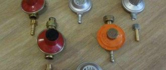
For example, scraps of pipes of different sizes, an old gas cylinder and other metal scraps will be turned into a furnace, and waste oil will be turned into fuel. Organizing heating using waste oil with your own hands is not so difficult.
We will tell you about the main options for installing heating systems using waste fuel. The article we have proposed describes in detail how to manufacture home-made devices that have been tested in practice. Taking into account our recommendations, you can achieve optimal results.
What is mining and how to use it
Essentially, it is used motor oil, lubricating the engine and chassis. During the operation of equipment, oil, an initially fairly pure petroleum product, becomes saturated with slag - metal particles (the result of friction and mechanical damage to parts), soot, salts, and resinous compounds. As a result of such saturation, the oil is no longer suitable for lubrication, but it burns well - which allows the product to be used as fuel.
The composition of the waste burns approximately 85%, and during the combustion process it produces about 11 kW/hour of thermal energy per liter. Thus, the product’s fuel qualities are comparable to diesel fuel.
Important: if the oil is heavily clogged with solids, it is advisable to filter it before use.
At the same time, an oil furnace using filtered exhaust will work longer and better; it will have to be cleaned less often to remove carbon deposits.
Scope of use
The first such units were developed in order to dispose of waste oil products (they were called that way: recyclers). They were designed so that the percentage of harmful emissions was minimal. A little later they figured out how to use the generated heat for heating, after which many modifications of the devices appeared.
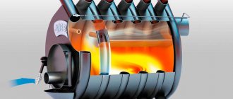
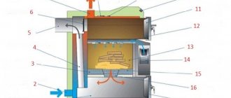
Visual operating principle of the burner Source gwsigeps.com
Modern heat generators are varied in design; They are designed for heating the following premises:
- Car service centers, technical centers, hangars.
- Locksmith workshops, industrial premises, warehouses.
- Other industrial premises, private houses and summer cottages.
Any natural or synthetic waste oil, or a mixture of several oils, is suitable for use. The fuel can be oil:
- waste: motor, hydraulic, transmission, transformer (from machine tools and any equipment);
- drained from cars, hydraulic equipment, diesel locomotives;
- drained from a cooking unit (for example, a deep fryer);
- vegetable oils: rapeseed, soybean, corn, sunflower (waste);
- diesel fuel, kerosene.
- fuel oil, heating oil.
Where to use a homemade furnace for mining
Since during the combustion process engine oil, especially used one, does not emit the most pleasant odor, and from a health point of view it is not very useful, it is better not to use stoves of this kind in residential premises. If there is no other way out, high-quality removal of combustion products is mandatory.
Typically, stoves are installed in non-residential premises - utility rooms, garages, sheds, workshops, and so on - where constant heating is not required, but only warming up the air for a relatively short time.
Due to the fact that even the simplest designs of such a “ garage potbelly stove ” make it possible to regulate the intensity of fuel combustion, it is possible to ensure either an economical mode of its use and gradual heating of the premises, or increased consumption with very fast heating of the air volume.
Ventilation.
Ventilation holes for exhausting the atmosphere should not be blocked by anything. Or there will be an increase in carbon monoxide in the room, which can cause poisoning. Stoves burn in the absence of soot and smoke, there is no aroma, and are in many ways more efficient than a wooden stove. The heat of the oven is up to 900 degrees - rapid heating. Acceptable auxiliary equipment is a fan, automatic oil supply, water tank, boiler, heater. The bent chimney increases the warm air supply. Operating rules Any oil, artificial or mineral, is suitable for using the stove. It is possible to pour no more than half of its size into the tank, because there must be room for the formation of vapors. When you have poured the oil, you need to take time for the vapors to become enriched with oxygen, after which they are ignited using long matches. As soon as the vapors ignite, the damper must be closed halfway; after heating the furnace, place the damper in this position so that the gases burn moderately in the central chamber.
General principles of operation of a furnace for a garage or summer cottage
The essence of the process is simple: since the oil itself does not burn so much as it smokes, it must be heated to boiling point and the released vapors must be ignited. Accordingly, you need a container for heating the oil, air supply points and an afterburner chamber. And, of course, the chimney.
The diagram below shows the principle of the simplest stove with a square fuel tank.
So:
- approximately ½…2/3 of the volume is filled with waste into the fuel tank, also known as the firebox. This is no longer possible - either during the boiling process the oil will splash out, or simply not enough flammable vapors are formed;
- after the fuel has settled a little in the tank and gives off a certain amount of evaporation, the contents are set on fire. This is done with the help of a “torch” - a burning splinter, a rag (preferably also oiled), paper. Next, the filling hole is closed and not opened again until the fuel burns out;
- when heated, the oil begins to produce more and more vapors; they rise to the afterburning zone, mixing along the way with secondary air. Since the heated vapors are much higher in temperature than the air surrounding the pipe, oxygen is drawn into the holes very actively, contributing to an increase in the combustion temperature. The draft can be adjusted using dampers, thereby increasing or decreasing the intensity of vapor combustion;
- heating of the surrounding room occurs due to heat exchange between the hot combustion chamber, pipes, afterburning chamber and air. To ensure that the device releases heat longer, a damper is placed between the afterburning chamber and the chimney, reducing the rate of removal of heated and burning vapors.
To ensure uniformity of the process, the afterburning chamber and the firebox are made of approximately the same size (volume).
If the stove is made correctly, the flame has a white-blue color. Accordingly, the combustion temperature is 1000 degrees Celsius and higher. If the flame has golden-orange, reddish tones, the combustion temperature is clearly insufficient - weak draft, low heating of the exhaust, design problems in general. With a blue-white flame, the soot formed during the combustion process partially burns out before reaching the chimney, which significantly reduces the necessary frequency of cleaning the smoke ducts.
Regardless of how correctly the structure is designed and executed, soot and soot will certainly form in it, and non-combustible sediment will accumulate at the bottom of the fuel container. Therefore, it is necessary to make the oven as collapsible as possible - this will make cleaning it much easier.
Features of the chimney device
The length of the chimney in these stoves is assumed to be at least 4 m. This is necessary both to create proper draft and to ensure high-quality removal of combustion waste. It is also important to provide high-quality ventilation in a heated room, since some of the combustion products somehow end up not in the chimney, but inside the room.
The diameter of the chimney is assumed to be at least 100 mm, and the presence of elbows, turns, and complex shapes is extremely undesirable - cleaning the chimney is necessary much more often than with conventional stoves, since the fuel produces a large amount of soot.
The best option for installing a potbelly stove is strictly under the hole in the roof through which the chimney will be led out. In this case, the vertical position of the chimney will ensure stable draft and easy cleaning. The outer part of the pipe must be insulated. If this is not done, condensation mixed with unburnt soot will settle on the inner walls, quickly narrowing the passage for smoke.
Assembly and commissioning
The bodies of such boilers consist of two pipes inserted into each other, the radius of which should differ from each other by 30–40 mm. The external part must be equipped with 2 outlets - for direct and reverse supply of coolant. And inside the smaller-diameter pipe is a combustion chamber. The waste container is located next to the boiler - a pump is immersed in it to supply fuel to the pyrolysis chamber.
The further installation process includes the following steps:
- Placing another container for oil at the bottom, with the creation of holes in it for gas vapor to enter the chamber for secondary combustion;
- Conducting contacts for electrical ignition of the burner through the combustion door;
- Inserting a fitting, thanks to which a gas-air mixture is formed, into the chamber wall;
- Creation of a chimney with a slide damper to remove combustion products, which the diagram provides;
- Placement of a gas outlet tube lowered to the level of the bowl with oil;
- Installation of a circulation pump on the return line, and safety groups on the direct line.
Before starting to operate the equipment, check the degree of sealing of the seams by filling the appropriate containers with oil and water. It is recommended to carry out the first launch by pouring only a 10 mm layer of oil purified from mechanical impurities with the addition of 100 ml of kerosene. The waste is ignited using a wick dipped in lighter fluid and lowered to the bottom of the container.
How to make a working furnace: basic principles
Regardless of what type of furnace - supercharged, drip type, with an expansion tank, additional combustion of gases, a water circuit - is chosen for execution, there are general principles for its manufacture.
- High combustion temperatures require large thickness of the walls of the structure. For the upper chamber you need a steel sheet of at least 6 mm, for other parts 4 mm is enough. Instead of sheet steel, you can use barrels, cylinders and other used products of a suitable configuration.
- As mentioned above, the structure must be collapsible. Consequently, permanent connections are unacceptable; bolts, clamps, etc. are required.
- The product is quite compact and light, usually weighing less than 30 kg (without fuel). To prevent the stove from tipping over, it must be secured to the floor.
- As a result of strong heating, the floor may be damaged; it is advisable to make the stove on legs. The height of the legs depends on the floor material - the more flammable it is and the worse it perceives heat, the higher the chamber with burning fuel should be. In this case, the legs should be made of adjustable height and be sure to check the correct position of the stove when installing it with a level - the fuel tank is positioned strictly horizontally.
- The dimensions of the furnace are taken for reasons of ease of installation and sufficient heat transfer (more on this later). Typically, the dimensions fit into a parallelepiped 75x50x35 cm. The height of the chambers (fuel and afterburning) is about 10...15 cm, their width is 30...40 cm. The average volume is 10...30 liters.
- The pipe connecting the chambers is made perforated. The ratio of its diameter to length is 1:4 (approximately), the hole size is 10...16 mm, the total area of the holes is 10% of the total surface area of the pipe.
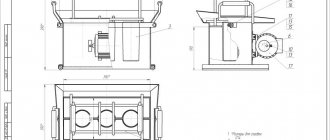
Below is a drawing of the simplest design of a mining furnace.
The legs are not shown in the drawing; they are manufactured locally. The chimney is also not shown.
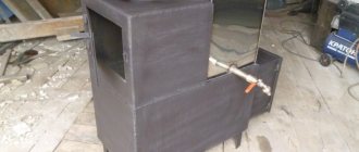
This is what the finished structure looks like during operation.
The video shows an example of a working furnace with a retractable compartment for filling fuel.
Device: design subtleties of a homemade unit
The performance of the device depends on the degree of readiness of the oil to be converted into a flammable gaseous state. With proper organization of the heating process, it burns without a residue, producing harmless smoke that does not contain toxic impurities.
To achieve this result, it is recommended to mount a container below in the form of a thick-walled (over 5 mm) cup, into which the waste is fed intermittently in the form of drops. Evaporation occurs completely until the next portion arrives.
Boiler installation during testing.
It is necessary to develop a mechanism for preheating the bowl. This can be an extraneous source of fire, such as a blowtorch, or a wick impregnated with a flammable substance and operating with the oil supply turned off before starting the boiler. To prevent the unit from cooling, it is possible to provide for the flow of waste in the “idle” mode.
Jet supply of oil leads to the accumulation of its unevaporated components on the walls of the unit. It is important to organize the supply of clean fuel in small portions. This could be a homemade dispenser or a modification of mechanisms from other units.
Fuel for the boiler comes with contaminated friction products from metal parts in the form of grains or shavings.
To eliminate solid fractions, an automobile oil filter is included in the fuel supply system.
Example of calculating furnace dimensions
As mentioned above, fuel consumption is about 1...2 liters per hour. At the same time, the radiated heat is about 11 kW/hour per liter. Thus, the furnace can produce 11...22 kW per hour. To calculate the required volume of the firebox taking into account the burning time, we accept:
- volume of the room (garage) – 7x4x2.5=70 cubic meters, area 28 sq.m.;
- We believe that for every square meter of a garage-type room, at least 500 W are required (basic 100 W, we enter coefficients for all external walls, non-insulated roof and foundation, large entrance opening, metal structure);
- Accordingly, an area of 28 squares requires 14 kW of energy per hour.
By slightly increasing the minimum power of the stove (increasing the draft), we will obtain the required temperature in the room. But fuel consumption will increase to approximately 1.5...1.6 liters per hour. Therefore, for a burning time of at least 6 hours, the volume of the firebox should be 10 liters. This corresponds to 0.001 cubic meters, that is, the container should have a size, for example, 10x10x10 cm. In reality, the volume of the firebox exceeds the required volume of fuel by 1.5...2 times, that is, the dimensions should be 20x10x10 cm or more, this is suitable for a mini stove. Usually they take it with a substantial reserve, that is, 50x30x15 cm. This allows you not to add fuel every time you ignite.
Important: with large firebox sizes, it becomes necessary to extinguish the fire in the furnace during exhaust before the fuel burns out completely. The extinguishing process is shown in the video.
The length of the pipe is 40 cm, respectively, its diameter is 10 cm. The area of the lateral surface of the cylinder is equal to its height multiplied by the circumference of the base (diameter multiplied by the number π), in our case 40x3.14x10 = 1256 cm2. Accordingly, the area of all holes is one tenth of the total - 125.6 cm2. Considering that the area of one hole with a diameter of 10 mm is equal to πx0.52=3.14x0.25=0.78 sq.cm, such a pipe will require 125.6/0.78=160 holes.
Note! The accepted value is the area of the holes 10% of the total area of the side surface of the pipe - conditionally! The number of holes during manufacturing is taken, among other things, from the strength of the product and is usually noticeably less!
Considering that the unfolded cylinder is a 31x40 cm rectangle, and the holes should be placed in a checkerboard pattern, we will have to make 12 vertical rows of 13 or 14 holes each. Marking vertical rows is simple - divide the upper or lower circumference of the base of the pipe into 12 parts in any geometric way and draw vertical drilling lines.
The distance between the rows will be 3.3 cm. Marking the vertical rows is a little more difficult, since in every second row it is necessary to shift the upper (or lower) marking point by half the distance between the holes. Considering that we need to make holes not on the edge of the pipe, we add 1 to the planned number of holes and calculate the step: for 13 holes it will be 40/(13+1)=2.85 cm, for 14 – 40/(14+1) =2.6 cm.
Important: when drilling, the axis of the drill must be directed towards the axis of the pipe!
Instructions for making a furnace for testing with a drawing
Let's take the drawing below as a basis.
Required:
- sheet steel 4 mm and 6 mm (sheet sizes depend on the selected dimensions of the furnace, check according to the drawing), steel pipe with a diameter of 100 mm and a length of 400 mm;
- grinder with a disc for cutting metal;
- welding machine;
- metal drills and drill;
- a sheet bending machine or other device that allows you to bend a sheet into a cylinder;
- studs or bolts with a thread of at least M12, corresponding nuts and washers.
Sequencing:
- Reveal the details. We cut out the elements according to the dimensions shown in the drawing. For rings, strips are used, the width of which is equal to the height of the ring, the length is equal to the circumference with a margin for welding. For example, for a ring with a diameter of 352 mm and a height of 60 mm, a strip of 60x1105 mm will be required. Welding margin is 1…1.5 cm, butt welding is possible.
- Holes of the appropriate size and shape are cut in the finished parts. We take into account the tolerances of the parts - it is better to try on the size of the hole “in situ”. Holes in the pipe are drilled based on the planned combustion intensity and strength conditions: the more holes, the stronger the draft, but the less strong the pipe. Usually holes are drilled in increments of 7…10 cm.
- We first assemble two blocks - the fuel chamber and the afterburner, then fasten them to the pipe. At the same time, to maintain the possibility of disassembly, we do not use welding, we only tightly insert the parts into one another! You can sand or trim the edges a little to make it fit.
- Lastly, the legs are welded and the valves and lids are secured in place - always with bolted connections so that there is access to the containers for cleaning. It is also advisable to weld spacers between the fuel tank and the afterburner chamber. For spacers, you can use reinforcement or any suitable rod.
- The chimney is installed and secured to the structure with bolted or stud connections.
Below is another version of the diagram and drawings of the furnace for do-it-yourself testing. Cylindrical compartments are also used here, but the axes of the cylinders are turned parallel to the ground.
This video shows the assembly of such a stove and the process of its operation.
Results
Thus, do-it-yourself oil heating is a fairly economical system, and at the same time, worthy of replacing other heating systems. Such systems are also used for autonomous heating. However, the specificity of this option lies precisely in the fuel used, so this alternative is considered as an extreme case: when there are no other options or there is a lot of used oil. The main area of application for such devices is industrial enterprises, where among the waste there is a large amount of used oil.
Types of furnaces for mining
It has already been said above that the simplest potbelly stove is not very convenient or effective. Therefore, various modification options have appeared, which we will consider below.
Exhaust stove from an old gas cylinder
Here you will also need 4 mm sheet metal (about 50 sq. cm), but another basic element is more important - a waste gas cylinder with a capacity of 50 liters, better than the old Soviet model, propane. Oxygen is heavier and more massive, making it difficult to work with. In addition, you need:
- steel pipe with a diameter of 100 m, a length of 2000 mm;
- valve with ½ inch thread;
- steel corner with shelf 50 mm, meter or a little more;
- clamps;
- loops;
- a piece of fuel supply hose;
- car brake disc. We select the diameter so that it fits freely into the cylinder;
- another cylinder (freon) to create a fuel tank.
Sequence of work:
- we drain the remaining gas from the cylinder, drill a hole in the bottom and rinse the cylinder with water;
- We cut out two openings in the side wall - a large lower one and a smaller upper one. The fuel chamber will be located in the lower one, and the afterburning chamber in the upper one. By the way, if the dimensions of the lower opening allow, in addition to mining, it will be possible to use firewood as fuel;
- We make the bottom of the afterburning chamber from a steel sheet;
- We make a burner from a pipe - a place where volatile gases mix with air and ignite. Holes are drilled in the burner (according to the principle described above), the inside of the pipe is GRINDED, this is necessary for greater efficiency of the product;
- the finished burner is welded into the bottom of the afterburner chamber;
- We make a waste tray from a brake disc and a piece of steel sheet. We weld the lid in its upper part;
- It is better to use a coupling to connect the burner and the pan cover - this makes servicing the stove easier;
- We provide a fuel supply. To do this, a hole is made in the wall of the cylinder into which a pipe with a threaded edge is welded;
- A valve is placed at the outer end of the pipe and a hose is connected to it. The hose, in turn, is connected to the fuel cylinder;
- the chimney pipe is welded into the upper part of the cylinder, then “taken away” in a smooth upward transition until leaving the room.
In fact, this completes the work with the furnace itself, but it is better to additionally build a heat exchanger - this will increase efficiency.
One of the heat exchanger options - plates welded onto the body - is shown in the photo below.
The finished oven with the doors open (the hinges were needed specifically for them; the pieces of the cylinder cut out in step 2 are attached to the hinges).
Pressurized furnace in operation
This design is also assembled on the basis of a 50-liter cylinder.
The air supply here comes from a fan (for example, from the stove of a VAZ 2108 car), which allows you to increase the draft in the afterburner and at the same time actually make the entire surface of the cylinder a heat exchanger.
The operation process and ignition are shown in the video.
Exhaust furnace with water circuit
Manufacturing a furnace with a water circuit can be almost the same as in the simplest version. The main difference is the organization of heat extraction into the water coolant. In the photo below, this possibility is realized by winding a pipe around the furnace body. In this case, cold water is naturally supplied from below, and heated water comes out from above.
A more “advanced” option is a stove with a “water jacket”. In fact, the body is enclosed in a second, hollow one, inside of which water circulates. The heated liquid is supplied to heating radiators.
True, the phrase “does not smoke” from the manufacturer is a bit of an exaggeration - this is only possible with regular cleaning of the chimney and the use of sufficiently high-quality, filtered fuel.
In the drawing, the device looks something like this.
Drip furnace
This type of stove is safer than those designs into which fuel is poured at once. In addition, in the case of gradual feeding, the burning duration can be freely adjusted.
A mandatory element of the system is a separate fuel tank, the waste from which is supplied in small portions - almost drops - using a special device.
The photo below shows a design where there is a separate tank with an oil line located above the fuel chamber. The base of the furnace is a gas cylinder; a valve is used to regulate the flow rate of the waste. The design of the furnace is discussed in more detail above.
Another type of product is with a retractable fuel compartment and a double afterburner.
It is realized in metal.
Please note: due to supercharging and the absence of fuel losses during filling, the exhaust consumption is reduced by 20...30%.
Safe Operation
The indifference of the furnace to the composition of the mixture that makes up the waste does not negate control over its quality. The presence of flammable impurities (gasoline, acetone, kerosene) leads to malfunction and, in severe cases, to damage to the device.
It is necessary to exclude the possibility of water entering the combustion chamber. A leak in the water jacket will damage the device. There may be a spill of burning diesel fuel.
The working surfaces have a dangerous temperature, therefore, when installing the boiler, contact with them while being nearby is prevented in order to avoid burns.
Periodic cleaning of the burners and the evaporation chamber when cold is necessary. Contamination reduces the efficiency of the installation and leads to incomplete combustion of fuel with the formation of soot that settles on the air ducts.
In the room where the heating device is installed, oxygen burns out, which requires thoughtful ventilation. The air in the boiler room becomes dry from contact with the boiler and chimney, so it needs to be humidified.
Burner contamination reduces the efficiency of the installation.
Mining is flammable, it is important to be careful when storing supplies.