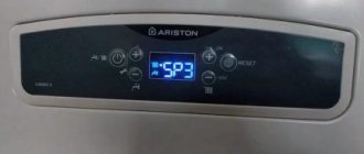
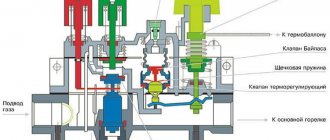
In private homes, the main source of heat is a heating boiler. In order to control the heating process of the equipment, a temperature sensor is needed for the heating boiler. It is on its normal operation that both the comfort throughout the house and the safety of the heating equipment largely depend.
Design and principle of operation
Heating boilers can be supplemented with temperature sensors, both internal and external (remote).
The built-in ones are responsible for adjusting the heating installation depending on the temperature of the liquid inside the heating system.
External ones help to adjust the operation of the heating installation in accordance with the readings of either room or street temperature. The joint use of a pair of such sensors makes it possible to more accurately regulate the operation of the boiler installation, which means there is energy saving when weather conditions change.
The operation of the devices consists of constant measurement of processes:
- resistance;
- pressure;
- thermal expansion.
Which are in direct connection with the temperature of the heating system filler.
Automatic thermostats work according to the program embedded in them, controlling the operation of heating devices.
Mechanical controllers, when exposed to high temperatures, are capable of changing their thermal conductivity by closing/opening the connections of the corresponding valves.
All temperature sensors are placed in a special, small-sized block housing with installation directly into the heating structure.
The results obtained can be transmitted over a wireless communication channel, such as WI-Fi, or transmitted over wires.
Both electric and solid fuel boilers can be controlled by temperature sensors.
The programming function using a thermal relay paired with temperature sensors allows you to automate the procedure for adjusting the heating system. In addition, this makes it possible to significantly reduce heating costs.
In general, the entire structure can be equipped with three temperature monitoring devices:
- Indoor.
- Street.
- For water-based underfloor heating systems.
Standard sizes
Standard sizes of thermistors themselves: rods, tubes, disks, beads, plates, drops, tablets. Sizes 1–10 µm to several mm and 1 cm.
There are also SMD formats and micro-rectangles.
We can immediately distinguish between the sensors as ready-to-use products and the “bare” thermistors themselves.
Sensors as devices can be made in any form, housing according to the manufacturer’s decision, for example, probes, probes, “chips” with connectors, in a waterproof housing, with threads, on a long cable.
Sensors as ready-made devices
Automotive:
Invoices. On the surface of structures. Examples: T2C-NTC 10K for −50…+150° C; ALTF02 S+S for collecting data from solid objects (pipes).
Channel, submersible. For cavities. T3-NTC 10K with 30 cm cable, for +50…−50° C; T2I-NTC 10K, 6.5 cm, −50…+150° C; TF43T and TM54 for liquids in pipes and containers.
External. For weather-sensitive complexes, on external walls (ATF01 S+S Regeltechnic).
Rooms. For interior spaces, apartments, offices.
Multifunctional. They combine other sensors to study not only temperature, but also pressure, density, etc.
Beaded
Beads, ball, drop, Ø 0.075 to 5 mm. Made of lead wires, an alloy with platinum, sintered in a ceramic, glass-ceramic shell. Better response and stability, their operating temperatures are higher than those of disk variants and chips.
Disadvantages: higher fragility, no interchangeability, require individual calibrations. There are no exact standards for their R/T ratings.
Discs, records, chips, tubes
Disc-shaped products with surface contacts. The shape is larger, the reaction is slower than that of balls. But due to their increased dimensions, they have good dissipation (power to increase temperature by 1 degree). Since the energy dissipated is proportional to the square of the current, they work better with high currents than balls.
Disc ones are made by pressing powder-like oxides into a round matrix, then sintered. Chips are injection molded, the suspension is distributed into a thick ball, then dried and cut. Dimensions Ø 0.25…25 mm.
Interchangeable, but there are errors, the minimum permissible deviation is considered to be at least 0.05 ° C within 0...+70 ° C. A standard 10 kOhm thermistor within the range of 0…+100 has coefficients close to the following:
Tube thermistor:
Encapsulated
Encapsulated ones resemble wafers, tablets, and may be similar to other types. The peculiarity of their coating is that it is especially sealed, airtight (bubble, capsule, container), made of fiberglass. For high temperatures, from +150° C, for boards where special strength is required. This design increases stability, protection, Ø 0.4…10 mm.
Classification of types of temperature sensors
In order to choose the right boiler temperature sensor, you need to know where it (temperature) will be controlled:
- from inside the boiler plant;
- ambient air temperature in the rooms;
- coolant inside the heating structure itself.
The correct installation location of the meter affects not only the efficient operation of boiler equipment, but also the safety of its use.
There are two main criteria by which the temperature sensor is selected correctly:
- How is temperature determined?
- How the sensor interacts with the thermostat.
Types of sensors by method of determining temperature
There are several ways to measure temperature:
- Dilatometric. It is directly dependent on the state of the bimetallic plate with a large coefficient of thermal expansion, which can expand under the influence of heat. Magnets specially placed inside increase the sensitivity of the sensor.
- Thermoelectric. It consists of a pair of dissimilar conductors, which, during thermal expansion, are capable of producing thermo-emf. It is distinguished by increased accuracy due to the fact that the length and cross-section of the cables do not have a significant impact on the measurement result.
- Manometric. They measure how much the state of liquids or gases in a certain limited volume changes when heated.
- Resistive. Special alloys with high thermal expansion are used. They are sensitive to the slightest temperature changes. Usually presented in the form of a coil with copper-plated wire, placed in a plastic case.
- Semiconductor. Available in two versions:
- nonlinear temperature thermistors with a simultaneous decrease in resistance when heated;
- posistors with a nonlinear dependence, which is expressed in an increase in the resistance coefficient when heated.
Types of contact sensors
A special temperature sensor for the boiler can be connected to the equipment in two ways:
- using wires through which temperature data is transmitted to the control controller;
- using wireless technology. They operate on a dedicated radio frequency.
But it should be taken into account that there are no miniature wireless devices for heating systems. To power the device, read information and simultaneously transmit a signal, a control controller is required. Therefore, a wireless thermostat can only be paired with a room sensor. And the temperature sensor itself is for small-sized boiler equipment.
How are they different from thermocouples?
NTC should not be confused with thermocouples: although the tasks are similar and there is a connection with electrical parameters, the principle is different. For the former, it is based on a change in the resistance of the sensitive part, for the latter, on the potential difference that changes during temperature transformations, created by two segments from different alloys with different electrical properties.
The NTC sensor is made of one solid piece of alloy, and the thermocouple is made of two metals, and measurements are based precisely on transformations of its resistance, and not on potential differences.
Where can I buy
Electronics for heating boilers are available for purchase in specialized stores in your city. But there is another option that has recently received significant improvements. You no longer need to wait a long time for a parcel from China: the AliExpress online store now offers the opportunity to ship from transshipment warehouses located in various countries. For example, when ordering, you can specify the “Delivery from the Russian Federation” option.
Follow the links and choose:
| Thermostat for gas boiler with Wi-Fi and remote control, 3A | Smart Wi-Fi thermostat Tuya for boiler | Smart Wi-Fi Touch Thermostat, Wireless |
| Digital LCD Thermometer with Water Temperature Gauge | Thermostat for gas boiler TUYA, wireless | Intelligent Thermostat, Temperature Controller |
Calculation, selection of NTC thermistors
They determine which thermistor is suitable by using the R/T curves, by creating graphs and tables of RT values, and by formulas. The procedure is complex, there are entire brochures and separate articles, so we will only indicate the basics.
The best, albeit complex, calculation formula is that of “Steinhart (Steinhart) - Hart”:
Calculations are usually done by radio electronics fans and specialists, especially for homemade products. It will be easier to select an element with a similar specification, and also use ready-made recommendations from specialists; the information is available online on special sites. There are hundreds of modifications of thermistors; accordingly, the specification tables are very large. Often a specific batch of similar series of thermistors has its own data.
There are hundreds of NTC thermistor specifications:
But still, calculations in most cases are extremely desirable, even if there is data from the manufacturer on the parameters and recommendations, since thermistors have highly nonlinear properties. Different copies of the same specification, even, for example, with the same values of B25/100 (sensitivity, we will consider below), may have different shifts R. Therefore, the formulas for this parameter provide only an approximate estimate. Accurate results require complex calculations.
Sensors for household or other appliances in factory standard sizes are devices in a housing that are completely ready for use, and so on, all the necessary calculations are made by the manufacturers.
Parameters for selection (usually displayed as graphs, diagrams):
- CVC;
- temperature/resistance ratio curve;
- heat capacity, dissipation constant;
- R values;
- tolerances;
- temperature Range. It is within their boundaries that NTC sensors can perform better than all similar products;
- time constant: the period for transition from one t° value to another. This is the period in seconds required to achieve 63.2% difference in t° from the initial reading to the final reading;
- sensitivity: level of response to temperature changes;
- stability of the controller while maintaining a constant temperature through feedback from the sensor.
First order approximation
The t°/Ohm dependence (RT graph) has significant nonlinearity, therefore, for practical circuits, so-called approximations are used for calculations. An example of such a “first order”:
The equation is valid only for a small temperature range and for t°, when k is almost constant at its different values.
Beta formula
There is also a beta equation (contains a constant "beta", β). This is the simplest formula that exists, often for homemade products, for example, this is what is used on Arduino. Gives results with an accuracy of ±1 °C. Covers the range 0…+100° C. The latter is dependent on a single material constant β, obtained by measurements (indicated in the thermistor specification).
There is no need to linearize the sensor response. The formula requires a 2-point calibration, typically no more than ±5 over the entire useful range.
Steinhart-Hart equation
The Steinhart-Hart algorithm is a better but more complex equation. To avoid complications, the previous method is usually used, but for users with algebra knowledge and calculation experience, this is the best method. This is the general formula to fit a thermistor curve:
The A, B, C constants are usually published by manufacturers and suppliers as part of thermistor specification tables. The deviation according to the described formula is about ±0.15° C within −50…+150° C, which is an excellent indicator. If high correctness is required, then the boundaries must be narrowed. The accuracy is ±0.01° C and is better observed within the range of 0…+100° C.
Which formula to choose
The selection of a suitable calculus for determining temperature from resistance measurements is based on the availability of computing power, and most importantly, on tolerance requirements. For some applications the 1st order approximation is sufficient, for other cases the Steinhart-Hart method is required and the sensor must be calibrated over a large number of measurements against a generated lookup table.
Placements
Naturally, the sensor must be placed in the zone of influence of the heater. Therefore, they are distinguished by the method of placement:
- overhead - installed with tight contact directly on the heated surface;
- submersible - placed inside the coolant;
- room - the room temperature is controlled;
- external - the state of the external environment outside the house is measured. They have a waterproof body.
Designation on the diagram
On the diagrams, NTC is indicated by a rectangle (empty) crossed out by an oblique line at the bottom with a horizontal leg; there is also a “t°” icon with a minus. PTC posistors have “+”.
Another designation option is a schematic image of a spiral (like the teeth of a cardiogram), crossed out by an oblique line with the same temperature symbol:
The sensor controls the boiler
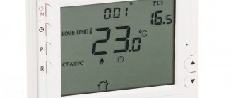
In order to more fully ensure comfortable living in a house with a minimum of thermal energy consumption, various devices are used. Such a temperature sensor for a gas boiler allows it to be programmed for different operating modes. The user just has to set the necessary parameters.
Mechanical thermostats
These models are the simplest. Without extensive functionality. They work through the use of membrane sensors located in a sealed capsule filled with liquid. When heated, the liquid expands and at a certain temperature puts pressure on the membrane and the thermostat makes it clear to the heating boiler that the power can be reduced/increased.
Mechanical devices are equipped with an expressive temperature selection dial. Due to their 3-4° accuracy and the wired connection method, these regulators are inexpensive.
Electromechanical
A slightly improved version of the previous temperature controller - electromechanical devices.
The principle of temperature regulation is similar to mechanics, but the operating principle is slightly different. The design uses heat-sensitive metals. When the heating changes, a micro-discharge is created or the resistance changes.
There are models with a small display for heating control and the possibility of adjustments in reduced steps. These changes were reflected in a slight increase in the accuracy of the device and in its price - it became more expensive than mechanics.
Electronic
More accurate electronic models are the most popular. These are more modern thermostats. They are multifunctional and easy to use.
- Can be used in conjunction with underfloor heating temperature sensors.
- Possibility of programming.
- There is protection against overheating and freezing.
- Warns that the circulation pump has stopped working.
- The measurement error is within 0.5–0.7 °C.
More advanced versions are equipped with built-in Wi-Fi for wireless connection to the boiler. Such a wireless room sensor, despite its high price, has a short payback period if used correctly.
Is it possible to disable
When installing the sensor and using gas equipment, you can often observe periodic shutdowns in operation. In this case, you may want to turn off the traction device completely. However, there is no need to rush.
Draft sensor for gas boiler AOGV and AKGV
There are several reasons for this:
- Firstly, a sensor disconnection may indicate poor traction performance. Weak intensity of movement of smoke gases leads to overturning of the draft in boiler equipment. Harmful fumes will enter the house in large quantities.
- Secondly, the problem may be backdraft. An air lock forms. The exhaust gases of the smoke move to a certain point in the chimney and then fall back. This occurs due to poor heating of the pipe and poor thermal insulation.
Of course, theoretically it is possible to disable the sensor, but this entails great danger. If an emergency suddenly arises, there will be no protection. Therefore, it is not recommended to operate a gas unit without such a controller.
How to choose a remote temperature sensor
What to look for when buying a temperature sensor? There are several options:
- A temperature meter needs extreme sensitivity and a wide range of measured temperatures. To quickly respond to changes in heating;
- sensor type - submersible or external. Is there a place for installation? It must match the dimensions of the water heater;
- temperature sensor parameters. Is there a need for additional voltage? At what speed is the signal transmitted and with what error. Ability to work in the right conditions;
- service life, maintenance frequency, need for additional calibrations;
- output signal level;
- permissible current, resistance, etc.;
When going to the store to buy a new device, it is better to take with you the technical data sheet for the heating installation.
Paired with thermostat
See how the temperature sensors will work with the boiler - with thermostat support or directly.
Many modern thermostats have the ability to adjust heating control depending on the weather. In this case, the power of the heating installation can be adjusted automatically if the thermostat is paired with an outdoor temperature sensor.
An outdoor thermostat is a single structure consisting of the sensor itself and a long (2–6 meters) wire for connection to the thermostat.
Should be considered:
- in what temperature range can the sensor for a gas boiler operate;
- level of moisture protection;
- the magnitude of the error in indoor air measurements. Permissible ± 1 °C. Good ± 0.5 °C;
- connecting cable length. Out of the box there is a wire up to 6 meters long with an attached temperature sensor.
Direct connection to the boiler
As a rule, those boilers that are purchased are already equipped with temperature meters and they are developed by the same supplier. If you want to install remote control of the boiler using a controller, you need a cable (usually two-wire). But you need to buy it yourself. The wire cross-section and resistance can be found in the instructions for the sensor.
They are usually connected to a thermostat. When automatically controlling the operation of boiler equipment, the connection is made to the controller, which brings the boiler to operating modes.
In any case, the connection is strictly regulated, according to the attached instructions.
Additional control devices, if necessary, can be recommended by the manufacturer of the boiler apparatus. This way you can guarantee the compatibility of devices and their correct operation.
If at the time of purchase the factory-recommended sensor for a gas boiler is not available, it must be replaced with certified analogues.
Outdoor sensor connection
An outdoor temperature sensor for boiler equipment is mounted on the outside of the building wall, subject to the following conditions:
- the temperature sensor should not be directly heated by the sun;
- the wall of the premises building should not be sheathed with metal;
- exclude the laying of cable lines in places where there is a possibility of rainfall;
- avoid contact with chemicals that may damage the insulation;
- the maximum height for placing a temperature sensor is 2/3 of the height of the house;
- exclude the influence of extraneous factors that may affect the external temperature sensor.
- protect the wire with an additional corrugated tube;
An external temperature sensor is connected, observing the polarity, when the boiler is not supplied with power. The main condition is that the cable with a cross-section of 0.5 mm² must be solid, and the length should not exceed 30 meters. The places where the cable is connected to the boiler and the meter must be insulated and sealed.
After connection, the quality of installation work is checked and the thermostat is adjusted. Additional inspection may reveal errors. In this case, a complete rework is required. Improper installation of an outdoor sensor can lead to either failure of the boiler equipment or poor heating of the premises.
Connecting the sensor inside the building
A room temperature sensor for a gas boiler is installed from the inside of the room on the outer wall, without violating the following conditions:
- Avoid being near heaters or air conditioners.
- Free access to the interior space. Eliminate all interior items that obscure the room sensor.
- The permissible height is 1.2–1.5 meters from the floor.
- There should be no nearby electrical wiring.
The method of connecting the device to boiler equipment is similar to an external temperature sensor.
Connecting a temperature sensor for a gas boiler
The temperature sensor for the gas boiler must be installed on the controller itself. As an option, installation on a gas valve is allowed.
Sequence of actions for self-connection:
- The instructions for the gas boiler must include a diagram. It contains the heating boiler itself and the place where the device is connected, its markings and the location of the contacts.
- Now on the gas heater itself you need to remove the front panel. It blocks access to the board and contacts.
- You need to remove the factory jumper between the terminals.
- Connect the wires from the sensor contacts to these terminals. The polarity of the wires does not matter.
- If a wireless air temperature sensor is installed to the relay unit, connect a three-wire wire with 220 V grounding.
If there are any doubts about the correct installation, it is recommended to refer again to the instructions for the gas boiler.
Main reasons for triggering
There are a number of main reasons why the controller may work, regardless of the type of combustion chamber installed in the gas installation.
You should not absolutely rely on the sensor's performance. Therefore, if possible, it is better to foresee negative scenarios in advance and eliminate the cause of their occurrence.
Poor quality traction
Poor quality traction is the main reason why the control sensor may work. This problem may arise due to improper design of the boiler and exhaust system. For example, poor-quality draft can be caused by a chimney with incorrectly calculated dimensions, if we are talking about a boiler with natural exhaust of combustion products, or a fan that does not operate at the required power, if it is a boiler with forced draft.
It is also worth checking the integrity of the output system. If the parts of the pipe are poorly connected to each other, the magnitude of the traction force will change.
Backdraft
Reverse traction force is a type of poor-quality traction. It is formed if a so-called air lock appears in the outlet system. If it is present, the gases that should exit through the outlet system to the street return back to the gas installation due to the fact that they cannot overcome the air lock.
This problem may arise due to poor thermal insulation (tightness) of the exhaust system pipes. As soon as the tightness of the pipe is broken, a temperature difference is formed, which provokes the appearance of an air lock.
To correct the problem of backdraft, you will have to repair the chimney.
Chimney blockage
A change in draft can also occur due to a clogged chimney. If its outlet is poorly protected from external influences, then, for example, foliage can get into it. But even good protection of the outlet does not guarantee its cleanliness. Birds can build a nest in a warm place and thereby affect the draft. But even the absence of birds does not guarantee good traction, because the output system can become contaminated with its own soot.
There is only one way out of the situation - regularly clean the chimney not only to eliminate problems, but also to prevent their occurrence.
Strong wind
If the outlet pipe is located in such a way that wind can blow into it, then you should prepare for the fact that this will affect the operation of the boiler. A gust of wind entering the pipe can overcome the resistance of the combustion products coming out towards them and blow out the burner.
If the controller does not work in such a situation, then the fuel will continue to flow uncontrollably into the boiler, but will not burn in it. To prevent such a development of the situation, you need to buy a stabilizer and install it in place of the outlet pipe.
Operating and safety features
Thermal sensors help improve the microclimate, but their normal operation depends on following simple rules:
- the element itself that measures room temperatures must be immersed as much as possible in the environment where it is necessary to improve heat transfer;
- Correct and long-term service of the room temperature detector depends on timely inspection and calibration in full accordance with the recommendations from the manufacturers;
- eliminate the negative impact of external factors that may affect the accuracy of temperature measurements for boilers;
- Operation of electrical sensors with damaged insulation is prohibited;
- Do-it-yourself disassembly of the thermostat is strictly prohibited;
- All preventative work is carried out with the equipment disconnected from the 220V network.
Prices
The cost of a thermocouple depends on the model and the alloys used in it. On average, prices are in the range of 350-500 rubles. Below is a table of thermocouple prices for the most popular models of gas boilers.
| Model | Cost, rub. |
| SIT 200 L=320 mm 0.200.003 for boilers Siberia 11, 11K, 17, 17K | 450-550 |
| SIT 200, L=750 mm - AOGV - AKGV EUROSIT SERIES | 500-560 |
| 55mm, M9x1 for Protherm Bear PLO, Panther 24 POV 0020027520 | 650-780 |
| L = 250 for Ariston/Ariston SGA 120 R, 150 R, 200 R | 1 500- 1 800 |
| Universal thermocouple 30 mv, 60 sec, 90 cm | 350-450 |
Gas boilersInstructionsBoilers
Replacement and connection
If the thermostat breaks down, then finding out the source of the breakdown is not difficult at all and can be done by the owner of the heating installation:
- If the water does not heat up, the source of the disease lies in both the temperature sensor and the thermostat. In this case, we do not consider the breakdown of the heating element. We assume that it is working properly.
- The temperature sensor is removed from the boiler and all wires are checked for breaks using a tester in the “continuity” mode.
- If the temperature measurements show zero when the thermostat is running, it is definitely faulty. You can’t fix it yourself; it’s better to buy a new one and replace it.
- If the thermostat responds to the boiler in the “call” mode, you need to set the minimum temperature value and take measurements again.
- If it is working properly, then in the “heating” mode its contacts should be open, and the resistance at the input and output should increase.
Replacing the thermostat with a similar one is described in detail in the instructions for the heater. If there is no such thing on sale, a similar one with the appropriate parameters is looked for.
Three ways to check the functionality of a thermal relay
Sometimes the heat supply is turned off too often for no external reason, and then it is worth making sure that the device is working properly. This can be done in several ways:
- A mirror is attached at the level of the thermal relay, and the system starts. During operation of the equipment, it should not fog up.
- You may not completely shut off the chimney: if everything works as it should, the system should automatically turn off immediately.
- If the controller turns off when the hot water supply mode is turned on without heating and the tap is open, the problem lies in the thermostat.
In certain cases, the sensor may periodically turn off on its own, and such a malfunction must be corrected as soon as possible: in an emergency, the security system will not work correctly, and waste may enter the house. To avoid emergency situations, it is necessary to regularly check the proper operation of the equipment, and its installation should only be carried out by professionals: a sensor installed at the wrong level or without taking into account the specific design will not be able to warn of danger in a timely manner.
Increased traction
If checking the chimney draft showed its complete absence or small value. You can also use a device such as a chimney draft stabilizer or turbine. True, their use is limited only to gas boilers. Too high a temperature of the exhaust gases at the outlet of the pipe will contribute to improper operation of the device or its failure.
If we talk about stoves or fireplaces, then in order for the chimney to work correctly during not very good weather conditions. Special tips - wings - are installed on the pipe. This device rotates freely so that its back is always facing the wind. This position prevents wind or rain from entering directly into the chimney.
Special fans can also be used. Such devices have a built-in electric motor. Their operating principle is as follows. Basically, they work from the wind; during strong gusts, the fan rotates, increasing the release of exhaust gases from the pipe; if the wind flows are not strong enough, then the electric motor turns on, which forces the fan to work forcibly and all harmful substances also end up on the street.
A small disclaimer: do not immediately after reading the article run to the store and buy a new device. Before you are going to install it, you should make calculations. And based on the results obtained, it will be clear whether this device can be installed on your chimney.
If there is no draft in the chimney, it will be useful to check the operation of the dampers. For stoves and fireplaces, this is a kind of regulator of the exhaust gas removal force.
What it is?
Pressostat, monostat, smoke sensor, differential smoke pressure switch, pneumatic relay - all these are different names for the same device. An important part controls the activity of the boiler fan, as well as the process of removing smoke, protects the heating apparatus from overheating during a sharp drop in gas pressure or when the amount of water supplied is reduced. In addition, the smoke sensor allows the burner to function or, conversely, causes it to turn off.
Visually, the pressure switch is a small flat plastic box , inside of which there is a sensitive membrane and a three-pin microswitch connected to it. It is these parts that control the operation of a complex heating apparatus.
Traction regulator functions
The main task will become clear if you look at the name of the device.
If you do not regulate the temperature of the coolant (water jacket), it will simply boil. Without an automatic regulator, you will either have to constantly add liquid or manually control the flow of air entering the firebox. The traction regulator greatly simplifies the life of private home owners. In addition to control, it performs two more useful functions:
- setting and maintaining the maximum permissible water temperature without boiling (up to 90° C; this is especially true in autumn or early spring);
- fuel economy (when the damper is closed, the intensity (speed) of firewood combustion decreases (albeit due to a decrease in boiler efficiency)).
Installing a draft regulator on a solid fuel boiler involves certain costs. To save money, some use a safety valve for similar purposes. For some reason it is considered an analogue of a regulator.
The solution is not the most rational, since after only 3-4 operations (turning off the boiler if there is a risk of overheating and reactivating it if there is excessive cooling), the accessory begins to leak.
The boiler does not produce hot water
The problem manifested itself as follows: when opening the hot water tap, the double-circuit boiler sometimes worked normally, but more often it simply did not light up, and did not show any errors. It just didn’t react at all, as if no tap had opened. At the same time, in heating mode everything worked clearly. It was also noticed that if the hot water tap was opened sharply and fully, then the boiler worked more often.
How does the boiler “understand” that hot water is open?
The electronic brains of the boiler “understand” that hot water is open and it’s time to switch to DHW mode thanks to the water flow sensor, also called the “Flow Meter.” Cold water passes through it, it rotates the turbine inside which there is a magnet, the magnetic field acts on the reed switch located in the outer part of the sensor and this signal is determined by the electronics as a command to turn on the boiler in DHW mode
Since everything happens like this, suspicions immediately fell on the fact that the water flow sensor was clogged with dirt and the turbine did not rotate; cleaning, unfortunately, did not yield anything. But logic said that we needed to dig there and it did not disappoint.
During a subsequent, more detailed disassembly, it was noticed that the plane of the turbine was so polished that it literally stuck to the body. If you have held ceramic elements from a half-turn faucet in your hands, you understand what I am talking about. These elements are so ground to each other that they literally stick together; for this they only need to be wet.
Oddly enough, the turbine also stuck in a similar way, which led to the boiler refusing to produce hot water.
Let's start the renovation
I’ll say right away that I carried out this procedure several years ago, everything works great. Today I specially removed and disassembled the flow meter in order to film everything and provide you with the whole process.
Don't forget before you get started.
- Disconnect the boiler from the network.
- Turn off the cold water supply tap to the boiler.
- Be sure to relieve pressure by draining the boiler.
I don’t recommend draining it through the relief valve - As experience shows, it’s better not to touch it again; if you touch it, it may start leaking, and you’ll have to deal with it too. It is better to drain the water through a drain valve specially designed for this purpose.
Only after this do we remove the bracket securing the water flow sensor.
Remove the bracket securing the water flow sensor
And here it is, the turbine! Now we need to remove it from the case. Let's look below.
It’s convenient to do this with a AA battery; it just goes inside, and we use it to squeeze out the node we need.
The extraction is complete, the turbine is covered in a red coating from the water; it won’t hurt to wipe it off either.
Now you need to carefully open this assembly, there are three latches, one of them will be wider than the others, this is the key for proper assembly.
In the top photo I am pointing with a screwdriver at a thin fluoroplastic washer. That’s what I put there to increase the gap between the plane of the turbine and the housing.
Without the washer, being on the axis, the planes of the turbine and the housing were in contact and polished, like magnets stuck to each other and the turbine did not rotate, this was the reason that the brains of the boiler did not receive a signal from the passing water.
I removed the washer from the mechanism of an old cassette recorder (I have a lot of this junk), but in general you can cut it yourself from dense polyethylene, for example from a plastic bottle or some kind of packaging.
This photo shows that these planes had no contact; they are red from the water.
We assemble in the reverse order, paying attention to the notch indicated above. When installing the unit into the housing, it should be directed in a certain direction.
Namely, you need to combine sides A and B. It won’t fit any other way. The battery will come to the rescue again to seat the knot all the way.
We insert it into the grooves and turn it, pay attention that the protrusions and guides on opposite sides have different sizes. Solve a logic puzzle
