The switching circuit of the metering device does not change: the selected input machine is connected in the same way as its predecessor.
Installation process of the introductory machine
The circuit breaker is installed on a metal profile (din rail). The batch switch is removed, after which the DIN rail is installed on the panel body using self-tapping screws.
Burnt parts of the wires are removed, their ends are cleaned. If necessary, the wires inside the meter are expanded by twisting, but the wires of the apartment circuits must be changed completely.
Conclusion
The need to replace old equipment with new ones is due to home safety precautions. Only after understanding what the introductory machine is needed for, what functions it has, and whether it should be connected to the network before or after the meter, you can begin to replace it. But before replacing the old device, you need to check the quality of the wires - any faults must be removed.
Switching circuit of the introductory machine
Connection diagram
When connecting an input machine, it is important to follow the rule that the common cable is connected to the upper terminals, and the taps must be made from the bottom. To determine the points for supplying the power cable cores, you will need to find contacts marked F1, F2, F3 and the neutral wire N
In the absence of special markings, the buses are connected to the contacts in ascending order of their number when counting from left to right along the comb. In a 4-pole device, the first three will be phase, and the next one after them will be earth. In a 2-pole analogue, the first one on the left is phase, and the next one after it is zero.
The location where any input device is included in the general power supply circuit remains unchanged. It is installed at the very input of the supply circuit up to the sealed electric meter. After it, it is allowed to install a protective shutdown device of the second stage of operation, which improves the quality of protection against electric shock. It is more convenient to install additional automatic devices and RCDs on a common DIN rail located in the distribution cabinet next to the meter.
Where should the RCD be installed?
To determine where to install the residual current device, you need to remember the speed of current flow through the wires. It is equal to the speed of light - 300 thousand km/sec. In a standard C 16 machine, the turn-on time when passing currents of 5×In (80 A) will be 0.02 seconds. The distance it will cover is 6000 km.
In the event of a short circuit, the current will completely pass through the coupling device - RCD - cable - socket. In this case, the switch does not operate instantly, as a result of which the insulation melts and the socket contacts burn out.
The RCD does not fail, since a short circuit is an inertial reaction. A time of 0.02 seconds is simply not enough to melt the insulating coating and damage the parts. Even taking into account the breaking capacity, the protective devices will work properly regardless of the installation location:
Protective devices will work properly regardless of the installation location
- Automatic - RCD. The phase is supplied using a jumper, and the zero is supplied directly to the protective device. The wire for the sockets is connected to the device and the PE bus.
- RCD - automatic. The wire is connected to the sockets through different paths. The phase one goes to the machine, the zero goes to the protection device or the zero bus.
Thus, there is no difference where the RCD was installed - before or after the automatic device.
Why is it unacceptable to install a circuit breaker on the neutral wire?
I corresponded via email with Volodymirom about the inadmissibility of installing a circuit breaker on the neutral wire of the electrical wiring. For those who want to understand the intricacies of this issue, I think its result will be useful.
Volodymyr: I’m currently making an electrical panel in the apartment and a question has arisen. Why can’t separate machines be set to zero and phase, but only paired ones? Why “It is strictly prohibited to install a single circuit breaker on the neutral wire.”?
Answer: When installing separate circuit breakers on the neutral and phase wires, designed for the same protection current, in the event of an overload of the electrical wiring, only one of them is likely to work. This is due to the fact that circuit breakers have a variation in the magnitude of the operating current.
If the machine installed on the neutral wire is triggered, then all electrical wiring, including the neutral wire, will be under phase voltage. The phase will reach the neutral wire through electrical appliances that are turned on at this time, for example, a TV in standby mode, a refrigerator. And if a person thinks that since the machine has worked, it means that the wires are de-energized and, therefore, safe, then he can start repairing the electrical wiring and accidentally come under dangerous voltage.
That's why it's impossible. It is possible to install twin circuit breakers in household electrical wiring, but there is no point in this, only extra costs, since a paired circuit breaker costs much more. Therefore, the neutral wire is laid directly, and a machine must be installed on the phase wire.
Volodymyr: If during a short circuit the zero-machine is knocked out faster, and the phase-man-earth short circuit continues, then the phase-machine will still be knocked out. Also, both can work approximately simultaneously. That is, the machine must be set to zero more powerful than the phase one. But there will be no disruptions to the network, only additional costs.
You can, of course, install a machine designed for a higher current on the neutral wire, but where is the guarantee that the machine will not fail? After all, the main value for any person is his health and life! Therefore, even with the hypothetical possibility of causing harm to a person, they do everything to exclude it.
Volodymyr: I’m just starting to master electrical installation in practice, including using your recommendations. And I want to understand the technical side in order to better understand the recommendations of the PUE. So forgive me if I'm wrong somewhere.
There are two common situations: 1. Short circuit phase-man-earth or phase-earth. A phase machine will work here. Zero machine has nothing to do with it.2. Short circuit phase-man-zero or phase-zero. A phase machine and/or a zero machine will work here. That is, if the phase machine does not work, then the zero one will break the circuit.
Answer: Your reasoning is based on the assumption that the machine serves to protect a person from electric shock. But the machine is designed solely to protect electrical wiring from destruction if the current flowing through it exceeds the permissible limit. To protect people, an RCD is installed.
Let me give you an example: a man decided to replace a light bulb in a chandelier and turned off only the switch, and not the machine, this is usually what they do. The wiring in the chandelier was old, and the neutral wire was touching the metal body of the chandelier. The man stood on the ground and, screwing in the light bulb, held the chandelier by the metal body with one hand.
At this time, another family member decided to turn on an electrical appliance, whose insulation at the exit from the plug had frayed and the wires were short-circuited. A short circuit occurred, and only the circuit breaker installed on the neutral wire worked, and a phase appeared on the neutral wire of the entire apartment wiring. As a result, a person changing a light bulb can receive an even fatal electric shock. The machine can also work when the lights are turned on if the light bulb burns out at that moment.
PUEs are written based on accidents involving electric shock to people and it is impossible to describe all situations in which people were injured or died. You just need to follow the PUE and then the electrical wiring will never fail.
Machine denomination
Table of ratings of circuit breakers
On the body of any device, the rated value is indicated - the value of the maximum continuous current that passes through the device without harm. This parameter is safe for current switching.
To ensure protection of the RCD itself, it is necessary to install a circuit breaker with a rating similar to or 1 more than the rating of the device. If you have a machine with a rating of 16 A, the RCD should be about 25 A. This current reserve will be enough to prevent the flow of energy when the load increases.
The machine is triggered when a current appears 13% higher than the nominal value: a 16 A modification will operate at a current of 18 A. If the RCD rating is equal, the contacts may heat up. To select the rating of a system with several circuit breakers, you need to sum them up and select an RCD with a larger rating.
Unacceptable mistakes when purchasing
The most common mistakes when choosing and purchasing an input circuit breaker are ignorance of the principles of its operation and choosing a machine rating lower or higher than the required value. If you choose a machine with a lower rating, then it is possible that the protection will trigger falsely and shut down the entire apartment due to one device.
There are also “professionals” who connect two single-pole circuit breakers instead of a two-terminal circuit, not knowing that this violates electrical safety requirements and the PUE prohibits such a connection.
If you have doubts about the selection and installation of such a device, you should contact a professional electrician and rest assured that the correct choice and safe installation.
Regulatory documents and rules for shields
All diagrams and apartment panels must be assembled in accordance with regulatory documents and not contradict the instructions and rules prescribed there
First of all, this is, of course, the PUE, but there are two more documents that are worth paying close attention to:
- GOST 32395-2013 Distribution panels for residential buildings. General technical conditions. (download)
- Code of rules for design and construction SP 31-110-2003 “Design and installation of electrical installations of residential and public buildings” (download)
Requirements from the rules for apartment panels
Notes and requirements from the above GOST that you should pay attention to when assembling and choosing an apartment panel:
Electrical wiring and cable lines
7.1.32. Internal wiring must be carried out taking into account the following:
1. Electrical installations of different organizations, separate administratively and economically, located in the same building, can be connected by branches to a common supply line or fed by separate lines from the ASU or main switchboard.
2. It is allowed to connect several risers to one line. On branches to each riser supplying apartments in residential buildings with more than 5 floors, a control device combined with a protection device should be installed.
3. In residential buildings, lamps in staircases, lobbies, halls, floor corridors and other indoor premises outside apartments must be powered via independent lines from the ASU or separate group panels powered from the ASU. Connecting these lamps to floor and apartment panels is not allowed.
4. For staircases and corridors with natural light, it is recommended to provide automatic control of electric lighting depending on the illumination created by natural light.
5. It is recommended to supply power to electrical installations of non-residential buildings using separate lines.
7.1.33. Supply networks from substations to VU, ASU, main switchboard must be protected from short-circuit currents.
7.1.34. Cables and wires with copper conductors should be used in buildings
Supply and distribution networks, as a rule, must be made of cables and wires with aluminum conductors if their design cross-section is 16 mm2 or more.
The power supply of individual electrical receivers related to the engineering equipment of buildings (pumps, fans, heaters, air conditioning units, etc.) can be provided by wires or cables with aluminum conductors with a cross-section of at least 2.5 mm2.
In museums, art galleries, and exhibition spaces, it is permitted to use lighting busbar trunking systems with a degree of protection IP20, in which the branch devices to the lamps have detachable contact connections located inside the busbar trunking box at the time of switching, and busbar trunking systems with a degree of protection IP44, in which the branching devices to the lamps are made with using plug connectors that ensure the branch circuit is broken until the plug is removed from the socket.
In these premises, lighting busbars must be powered from distribution points by independent lines.
In residential buildings, the cross-sections of copper conductors must correspond to the calculated values, but not be less than those indicated in Table 7.1.1.
1 Until 2001, according to the existing construction backlog, the use of wires and cables with aluminum conductors was allowed.
Table 7.1.1. The smallest permissible cross-sections of cables and wires of electrical networks in residential buildings.
| Line names | Smallest cross-section of cables and wires with copper conductors, mm2 |
| Group network lines | 1,5 |
| Lines from floor to apartment panels and to the settlement meter | 2,5 |
| Distribution network lines (risers) for supplying apartments | 4 |
7.1.35. In residential buildings, laying vertical sections of the distribution network inside apartments is not allowed.
It is prohibited to lay wires and cables from the floor panel in a common pipe, common box or channel that supply lines to different apartments.
Fire-retardant installation in a common pipe, common box or channel of building structures made of non-combustible materials, wires and cables of apartment supply lines together with wires and cables of group lines of working lighting of staircases, floor-by-floor corridors and other indoor premises is allowed.
7.1.36. In all buildings, group network lines laid from group, floor and apartment switchboards to general lighting fixtures, plug sockets and stationary electrical receivers must be three-wire (phase - L, neutral working - N and neutral protective - PE conductors).
Combining zero working and zero protective conductors of different group lines is not allowed.
The neutral working and neutral protective conductors are not allowed to be connected on panels under a common contact terminal.
Conductor cross-sections must meet the requirements of clause 7.1.45.
7.1.37. Electrical wiring in the premises should be replaced: hidden - in the channels of building structures, embedded pipes; open - in electrical skirting boards, boxes, etc.
In technical floors, undergrounds, unheated basements, attics, ventilation chambers, damp and especially damp rooms, it is recommended that electrical wiring be carried out openly.
In buildings with building structures made of non-combustible materials, permanent, monolithic installation of group networks is allowed in the grooves of walls, partitions, ceilings, under plaster, in the floor preparation layer or in the voids of building structures, carried out with cable or insulated wires in a protective sheath. The use of permanently embedded wiring in panels of walls, partitions and ceilings, made during their manufacture at construction industry factories or carried out in the mounting joints of panels during the installation of buildings, is not allowed.
7.1.38. Electrical networks laid behind impenetrable suspended ceilings and in partitions are considered as hidden electrical wiring and should be installed: behind ceilings and in the voids of partitions made of flammable materials in metal pipes with localization capabilities and in closed boxes; behind ceilings and in partitions made of non-combustible materials 2 - in pipes and ducts made of non-flammable materials, as well as flame retardant cables. In this case, it must be possible to replace wires and cables.
2 Suspended ceilings made of non-combustible materials mean those ceilings that are made of non-combustible materials, while other building structures located above suspended ceilings, including interfloor ceilings, are also made of non-combustible materials.
7.1.39. In rooms for cooking and eating, with the exception of apartment kitchens, open laying of cables is allowed. Open wiring of wires in these rooms is not allowed.
In apartment kitchens, the same types of electrical wiring can be used as in living rooms and corridors.
7.1.40. In saunas, bathrooms, toilets, showers, as a rule, hidden electrical wiring should be used. Open cable routing is allowed.
In saunas, bathrooms, toilets, showers, laying wires with metal sheaths, in metal pipes and metal sleeves is not allowed.
In saunas for zones 3 and 4 according to GOST R 50571.12-96 “Electrical installations of buildings. Part 7. Requirements for special electrical installations. Section 703: Premises Containing Sauna Heaters" electrical wiring with an insulation temperature rating of 170oC must be used.
7.1.41. Electrical wiring in attics must be carried out in accordance with the requirements of Section. 2.
7.1.42. Through the basements and technical undergrounds of sections of the building, it is allowed to lay power cables with a voltage of up to 1 kV, supplying electrical receivers of other sections of the building. The specified cables are not considered as transit; laying transit cables through basements and technical undergrounds of buildings is prohibited.
7.1.43. Open laying of transit cables and wires through storerooms and warehouses is not permitted.
7.1.44. The lines supplying refrigeration units of trade and public catering enterprises must be laid from the ASU or main switchboard of these enterprises.
7.1.45. The selection of conductor cross-sections should be carried out in accordance with the requirements of the relevant chapters of the PUE.
Single-phase two- and three-wire lines, as well as three-phase four- and five-wire lines when supplying single-phase loads, must have a cross-section of zero working (N) conductors equal to the cross-section of phase conductors.
Three-phase four- and five-wire lines when supplying three-phase symmetrical loads must have a cross-section of zero working (N) conductors equal to the cross-section of phase conductors, if the phase conductors have a cross-section of up to 16 mm2 for copper and 25 mm2 for aluminum, and for large cross-sections - at least 50 % cross-section of phase conductors.
The cross-section of PEN conductors must be at least the cross-section of N conductors and at least 10 mm2 for copper and 16 mm2 for aluminum, regardless of the cross-section of the phase conductors.
The cross-section of PE conductors must be equal to the cross-section of phase conductors with a cross-section of the latter up to 16 mm2, 16 mm2 with a cross-section of phase conductors from 16 to 35 mm2 and 50% of the cross-section of phase conductors with larger cross-sections.
The cross-section of PE conductors not included in the cable must be at least 2.5 mm2 - in the presence of mechanical protection and 4 mm2 - in its absence.
Design and principle of operation of the introductory machine
The input circuit breaker limits the power consumed by users.
The input circuit breaker mounted in the distribution cabinet is primarily necessary to limit the user in the useful power consumed by him. If the current exceeds the value set by this device, it will turn off and completely de-energize the apartment or country house. Taking into account this purpose, it is necessary to consider the design of the input switch, as well as the principle of its operation and its location within the cabinet.
It also performs its main function - it turns off the serviced line when the current exceeds the permissible value due to an emergency overload or short circuit. But in this purpose it is used as the second stage of group protection. The first to operate is the linear device installed directly in the damaged circuit.
Like all other circuit breakers (AB), the device mounted at the entrance to the house consists of the following mandatory components and parts:
- Housings with a set of contact connectors.
- Executive modules that ensure its operation.
- Connecting bars and fastening elements in the distribution cabinet.
In any devices of this class (including devices used for input), two switching elements called releases are used as executive modules.
One of them, related to thermal action mechanisms, is designed in the form of a bimetallic plate, and the other - as an electromagnetic overcurrent relay. The first disconnecting unit is triggered when the current in the protected line exceeds its nominal value for a long time. The electromagnetic release comes into effect when a short circuit occurs in this circuit. The magnitude of the operating currents, as well as the time delays inherent in these devices, are determined by their time-current characteristics. Thus, it ensures the compatibility of two metals that are dissimilar in structure, the direct connection of which in the form of twisting, for example, is unacceptable. It is fraught with oxidation of both conductive materials and subsequent breakdown of contact. And this usually leads to heating of the joint and its gradual destruction.
The input machine is traditionally installed directly in front of the electric meter, which allows you to take into account all internal consumers, as well as register the absence of a connection to the supply line cable. The second case is when the apartment is completely de-energized and the meter is completely disconnected from the power supply.
Input devices, distribution boards, distribution points, group boards
7.1.22. A VU or ASU must be installed at the entrance to the building. One or more VU or ASU may be installed in a building.
If there are several economically separate consumers in a building, it is recommended that each of them install an independent VU or ASU.
The ASU is also allowed to supply power to consumers located in other buildings, provided that these consumers are functionally connected.
For branches from overhead lines with a rated current of up to 25 A, the VU or ASU may not be installed at the inputs to the building if the distance from the branch to the group panel, which in this case performs the functions of the VU, is no more than 3 m. This section of the network must be carried out with a flexible copper cable with with a conductor cross-section of at least 4 mm2, flame retardant, laid in a steel pipe, and the requirements for ensuring a reliable contact connection with the branch wires must be met.
For air input, surge suppressors must be installed.
7.1.23. Before entering buildings, it is not allowed to install additional cable boxes to separate the service scope of external supply networks and networks inside the building. Such separation must be carried out in the ASU or main switchboard.
7.1.24. VU, ASU, main switchboard must have protection devices on all inputs of supply lines and on all outgoing lines.
7.1.25. Control devices must be installed at the input of supply lines to the VU, ASU, and main switchboards. On outgoing lines, control devices can be installed either on each line, or be common to several lines.
A circuit breaker should be considered as a protection and control device.
7.1.26. Control devices, regardless of their presence at the beginning of the supply line, must be installed at the inputs of the supply lines in retail premises, utilities, administrative premises, etc., as well as in consumer premises that are administratively and economically isolated.
7.1.27. The floor panel must be installed at a distance of no more than 3 m along the length of the electrical wiring from the supply riser, taking into account the requirements of Chapter. 3.1.
7.1.28. VU, ASU, main switchboard, as a rule, should be installed in electrical switchboard rooms accessible only to maintenance personnel. In areas prone to flooding, they should be installed above the flood level.
VU, ASU, main switchboard can be located in rooms allocated in operational dry basements, provided that these rooms are accessible to maintenance personnel and are separated from other rooms by partitions with a fire resistance limit of at least 0.75 hours.
When placing VU, ASU, main switchboards, distribution points and group panels outside electrical switchboard rooms, they must be installed in places convenient and accessible for maintenance, in cabinets with an enclosure protection degree of at least IP31.
The distance from pipelines (water supply, heating, sewerage, internal drains), gas pipelines and gas meters to the installation site must be at least 1 m.
7.1.29. Electrical switchboard rooms, as well as VU, ASU, main switchboards, are not allowed to be located under toilets, bathrooms, showers, kitchens (except for apartment kitchens), sinks, washing and steam rooms of bathhouses and other rooms associated with wet technological processes, except in cases where Special measures have been taken for reliable waterproofing to prevent moisture from entering the premises where the switchgear is installed.
It is not recommended to lay pipelines (plumbing, heating) through electrical rooms.
Pipelines (plumbing, heating), ventilation and other ducts laid through electrical switchboard rooms should not have branches within the room (with the exception of a branch to the heating device of the switchboard room itself), as well as hatches, valves, flanges, valves, etc.
Laying gas and pipelines with flammable liquids, sewerage and internal drains through these premises is not permitted.
Doors to electrical rooms must open outward.
7.1.30. The premises in which ASUs and main switchboards are installed must have natural ventilation and electric lighting. The room temperature should not be lower than +5 oC.
7.1.31. Electrical circuits within the VU, ASU, main switchboard, distribution points, group panels should be made with wires with copper conductors.
Connection diagram
The input switch is used not only for electrical safety, but also to disconnect the consumer from electricity during repair work. For this reason, the machine is installed in front of the meters.
Only a professional electrician has access to the machine. Apartment owners have no right to interfere with the security system. In 90% of cases, the machine is installed in the entrance panel in apartment buildings and in external systems (poles, fences) for cottages.
Owners can install a backup machine, which is used for ease of maintenance. It is placed between the meter and group automation inside the apartment switchboard. The current strength of the backup device should be lower than that of the input device.
For a private house 380 v 15 kW
To calculate the input circuit breaker for a private home, it is necessary to take into account the following values: network voltage (U), power (P) of all electrical appliances that will operate in the network, a correction factor that takes into account the simultaneous inclusion of electrical appliances and the quality of the electrical wiring.
Calculation example:
Let us assume that the sum of the powers of all electrical appliances in a residential building is 15 kW (the same power in Russia is usually supplied to private residential buildings) at a voltage of 380 V. To calculate the current, we use Ohm’s Law for an electrical circuit:
I=P/U;
I=15000/380 = 39.47 A.
We introduce a correction factor. Since all electrical appliances in the house will not turn on at the same time and, taking into account the old electrical wiring, we accept the value of the correction factor equal to 0.85.
https://www.youtube.com/watch?v=7sz6sf-gUPg
In=39.47x0.85 = 33.55.
The closest nominal values of the machines are: 32 A and 40 A. We choose the denomination in the smallest direction. And we find that for our private house we need a three-pole or four-pole 32 A input circuit breaker.
Neutral mode for selecting an input machine
For various neutral modes, the following input machines are used
Selecting an input machine for the TN-S system:
The input machine for the TN-S system must be
- Single-pole with zero or double-pole,
- Three-pole with neutral or four-pole.
This is necessary to simultaneously disconnect the apartment’s electrical network from the neutral working and phase conductors on the power input side. since the neutral and protective conductors are separated throughout.
Selecting an input machine for the TN-C system:
For the TN-C power system, the input circuit breaker is installed single-pole (for a power supply of 220 V) or three-pole (for a power supply of 380 V). They are installed on phase working conductors.
Features of choosing a circuit breaker
Possible overloads and short circuits pose considerable dangers, ranging from failure of household appliances to injuries and fires. The device, popularly called an “automatic machine,” is used to protect supply lines. If you choose the right machine, the device will turn off the equipment in case of damage to the wiring, preventing it from catching fire.
VA-series devices are often installed in home networks, the operating principle of which is described above. You should choose a machine based on the cross-section of the wires and the expected load on the line. This information will be enough to make the right purchase. It is recommended to contact specialized stores or official dealers who value their reputation, and not the electrical market.
The technical characteristics of the device play a significant role when choosing. When choosing a machine for a shield, first of all, selectivity is taken into account - the principle of from most to least. That is, if there is a 40A automatic at the input, 20A goes to the sockets, and 10A goes to the lighting.
To determine the load on the network, you will have to remember your school physics lessons, namely Ohm's law. For example, let's take that appliances will be installed in the kitchen, the total power of which reaches 3000 watts. The general network has a voltage of 220 volts. It is necessary to divide the power by the voltage and you get 13.6 A. If you start from the nearest rating of available machines, a 16 A model is selected.
Note! The machines provide a certain number of operations. Of course, models from trusted manufacturers are more reliable, but, nevertheless, it is not recommended to use them frequently for switching on and off
Because of this, not only does the mechanism wear out, but also the contacts burn out, which leads to failure of the machine.
Wide range of devices available
Current machines can be divided into 3 groups: B, C and D. To prevent the machine from being knocked out immediately, a current delay is provided after connecting the electrical device. In other words, the device will be “silent” for several seconds after equipment with a high inrush current is connected to the network. The marking in this case acts as a coefficient. The machine turns off if the current exceeds the nominal value by so many times:
- B – 3-5. Mounted in residential buildings where there are no current surges;
- C – 5-10. Also finds application in residential buildings. Provides protection for equipment with weak starting currents (drill, washing machine, etc.);
- D – 10-14. Installed in factories with installations with high starting currents.
The models produced differ in the location of the conductor attachment and fit on the DIN rail. Therefore, if the machine is being replaced, it is recommended to choose a model from the same manufacturer. The installation of an automatic fuse itself, the desire to change plugs to automatic ones, is not the easiest task, which is recommended to be entrusted to a specialist, since working with electricity is quite dangerous.
At the moment, the leading positions are occupied by devices from the following companies: ABB, Legrand, Schneider. These are brands that produce reliable and durable equipment. If, when choosing a device, there is a desire to save money, the IEK brand is available.
Note! Now many are trying to fake the production of fuses, producing low-quality products. If you want to save money, you should not purchase suspiciously cheap models that can cause an emergency
Electricity metering
7.1.59. In residential buildings, one single- or three-phase billing meter (with three-phase input) should be installed for each apartment.
7.1.60. Calculation meters in public buildings that house several electricity consumers must be provided for each consumer, isolated in administrative and economic terms (studio, shops, workshops, warehouses, housing maintenance offices, etc.).
7.1.61. In public buildings, estimated electricity meters must be installed on the ASU (main switchboard) at the points of balance demarcation with the energy supply organization. If there are built-in or attached transformer substations, the power of which is fully used by consumers of a given building, the calculated meters should be installed at the low-voltage terminals of power transformers on combined low-voltage switchboards, which are also the building’s ASU.
ASU and metering devices for different subscribers located in the same building may be installed in one common room. By agreement with the energy supplying organization, settlement meters can be installed at one of the consumers, from which the ASU supplies other consumers located in the building. At the same time, control meters should be installed at the inputs of the supply lines in the premises of these other consumers for settlements with the main subscriber.
7.1.62. Estimated meters for the general house load of residential buildings (lighting of staircases, building management offices, yard lighting, etc.) are recommended to be installed in ASU cabinets or on main switchboard panels.
7.1.63. It is recommended to place residential meters together with protection devices (circuit breakers, fuses).
When installing apartment panels in the hallways of apartments, meters, as a rule, should be installed on these panels; installation of meters on floor panels is allowed.
7.1.64. To safely replace a meter directly connected to the network, a switching device must be provided in front of each meter to remove voltage from all phases connected to the meter.
Disconnecting devices for removing voltage from settlement meters located in apartments must be located outside the apartment.
7.1.65. After the meter connected directly to the network, a protection device must be installed. If several lines equipped with protection devices extend after the meter, installation of a common protection device is not required.
7.1.66. It is recommended to equip residential buildings with remote meter reading systems.
Calculation of an introductory machine for a household electrical network
In order to choose the right input circuit breaker based on the operating current, you will first need to take into account a number of factors that influence its specific value.
- Type of power supply at this facility (two-phase or three-phase).
- The total power of all loads connected to the line.
- The presence of unaccounted for leaks and the current state of electrical wiring (its wear and tear).
AB calculation for an apartment
The calculation of the device for a separate apartment is based on the following generally accepted rules:
- To enter such housing, only two-phase 220 Volt power lines are used.
- Calculation of current consumption is made by summing all consumers connected to sockets plus the power of light bulbs (lighters) turned on simultaneously.
- An adjustment is made to the resulting value with a margin of approximately 10 percent.
For each individual consumer or apartment, according to the standards, a strictly limited current load is allocated (no more than 40 Amperes).
Taking into account the limitations and amendments, the cut-off current of the input circuit breaker is calculated and selected. If it is necessary to change its value upward, this must be agreed with local energy services and the management company.
Calculation of a machine for a private house 380 and 220 Volts
It is possible to correctly calculate which machines to install in a private home only by taking into account the following points:
- What loads are supposed to be used in the subsidiary farm, and is there any equipment among them that requires three-phase power?
- The total number of these loads and the power consumed by each of them.
- If there is 380 Volt equipment (pumps, heating boilers, engines, etc.), a 4-pole circuit breaker is selected, and in their absence, a two-pole circuit breaker is selected.
For a three-phase network, the permissible current through the releases is calculated for each phase separately.
Selecting a specific value for the machine's rating is possible only after obtaining an exact figure for the total power connected to the line of single-phase or three-phase loads
Having decided how many amperes the machine is installed in the house, we proceed to the direct installation of this device, which is important for the power supply system.
The correct calculation and competent selection of an automatic input device is given special importance for the following reasons:
- The performance of the power supply system of a residential property (apartment or private house) depends on the correct selection of VA for current.
- There will be no constant operation of it at the slightest deviation in the connected loads.
- A machine with good characteristics and proven operation will allow you to quickly turn off an apartment or house if necessary.
Mandatory installation according to PUE and GOST
RCDs for lighting at objects of various categories in accordance with the requirements of PUE and GOSTs must be installed:
- In particularly damp and fire hazardous areas, where they are used as reliable protection against leakage currents.
- If it is impossible to install lighting fixtures with a safe supply voltage of up to 40 Volts.
- When arranging networks based on luminaires and lamps, the lowest point of location of which is below 2.5 meters.
Additional information: In particularly humid rooms with a 220-volt mains supply, in addition to the RCD, a step-down transformer must be used.
To assess the safe location of household lighting, you should know that with ceilings in most apartments at a level of 2.5-2.7 meters, the elements of a chandelier placed on it will be below the permissible limit. In addition, according to current regulations, RCDs are installed in the power circuits of the following objects:
- In lighting systems used on signs and advertising.
- For decorative lighting of monuments.
- In crowded places (at public transport stops, near route signs, etc.).
- At outdoor lighting facilities.
When updating or repairing home electrical wiring, you should know that you need to install an RCD on the lighting circuit in the bathroom and toilet. For a private house, you will need to add a bathhouse or sauna to this list, as well as a veranda, swimming pool, attic and basement.
Regulations
Other articles in the section: House electrical wiring
- 26 Rules for power supply and wiring of a wooden house. part 1, rules 1-7
- 26 Rules for power supply and wiring of a wooden house. part 2, rules 8-13
- 26 Rules for power supply and wiring of a wooden house. part 3, rules 14-26
- Anchor clamps and brackets
- Fittings for SIP 2
- Inserting cables from the trench into the house
- Input device. VU for a private house
- VRU. House input and distribution device
- GZSH. Main Grounding Bus
- Deep ground electrode
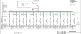
Electrical diagrams of the ASU
These are examples of various ASUs (Input distribution devices). Basic diagrams. Will open when clicked.
- VRU-3-11-10UHL4(250)-AVV
- VRU-3-17-70UHL4(100)-AVV
- VRU-3-20-00UHL4(100)-AVV (2 inputs, 9 automatic switch-offs at 100A)
- VRU-3-23-00UHL4(160)-AVV (2 inputs, 10 automatic switch-offs at 160A)
- VRU-3-40-60UHL4(250)-AVV (5 automatic switch-offs at 100A, without input counter)
- VRU-3-41-60UHL4(250)-AVV (5 automatic switches at 100A, with a counter at the input)
- VRU-3-42-10UHL4(250) -AVV (5 automatic switches at 100A, without input counter)
- VRU-3-43-10UHL4(250) - ABB (5 automatic switches at 100A, with a counter at the input)
- VRU-8504-3VR-2-12-55-AVV (with ammeters and voltmeter at the input)
Application area. Definitions
7.1.1.
This chapter of the Rules applies to electrical installations of: residential buildings listed in SNiP 2.08.01-89 “Residential Buildings”; public buildings listed in SNiP 2.08.02-89 “Public buildings and structures” (except for buildings and premises listed in Chapter 7.2): administrative and domestic buildings listed in SNiP 2.09.04-87 “Administrative and domestic buildings” ; Additional requirements may apply to electrical installations of unique and other special buildings not included in the above list. Further in the text, unless otherwise specified, the word “buildings” means all types of buildings to which this chapter applies.
The requirements of this chapter do not apply to special electrical installations in medical institutions, organizations and institutions of science and scientific services, to dispatch and communication systems, as well as to electrical installations, which by their nature should be classified as electrical installations of industrial enterprises (workshops, boiler rooms, thermal points, pumping stations, laundry factories, dry cleaning factories, etc.).
7.1.2. Electrical installations of buildings, in addition to the requirements of this chapter, must meet the requirements of the chapters of Section. 1-6 PUE to the extent that they are not changed by this chapter.
7.1.3. Input device (ID) is a set of structures, devices and instruments installed at the input of the supply line into the building or its separate part.
The input device, which also includes devices and devices of outgoing lines, is called an input distribution device (IDU).
7.1.4. The main distribution board (MSB) is a distribution board through which the entire building or its separate part is supplied with electricity. The role of the main switchboard can be performed by an ASU or a low voltage switchboard of a substation.
7.1.5. Distribution point (DP) is a device in which protection devices and switching devices (or only protection devices) are installed for individual electrical receivers or their groups (electric motors, group panels).
7.1.6. A group panel is a device in which protection devices and switching devices (or only protection devices) are installed for separate groups of lamps, plug sockets and stationary electrical receivers.
7.1.7. Apartment panel - a group panel installed in an apartment and designed to connect the network that supplies lamps, plug sockets and stationary electrical receivers of the apartment.
7.1.8. Floor distribution panel is a panel installed on the floors of residential buildings and intended to supply power to apartments or apartment panels.
7.1.9. Electrical room - room. accessible only to qualified service personnel, in which VU, ASU, main switchboard and other distribution devices are installed.
7.1.10. Supply network - a network from a substation switchgear or a branch from overhead power lines to the VU, ASU, main switchboard.
7.1.11. Distribution network - a network from the VU, ASU, main switchboard to distribution points and switchboards.
7.1.12. Group network - a network from panels and distribution points to lamps, plug sockets and other electrical receivers.
What are circuit breakers for and how do they work?
Modern AVs have two degrees of protection: thermal and electromagnetic. This allows you to protect the line from damage as a result of prolonged excess of the flowing current of the rated value, as well as a short circuit.
The main element of the thermal release is a plate made of two metals, which is called bimetallic. If it is exposed to a current of increased power for a sufficiently long time, it becomes flexible and, acting on the disconnecting element, causes the circuit breaker to operate.
The presence of an electromagnetic release determines the breaking capacity of the circuit breaker when the circuit is exposed to short-circuit overcurrents, which it cannot withstand.
This makes it possible to protect the wire and devices from an electron flow, the value of which is much higher than that calculated for a cable of a particular cross-section.
Operating principle of RCD, differences from difavtomat
The requirements of the PUE indicate the need to install protective equipment. It provides protection against electric shock and breakdowns of the cable insulation coating. The RCD can be connected to 2 wires in a network with a voltage of 220 V and to 4 wires in a network of 380 V.
The disadvantage of the device is the inability to detect overload or short circuit. An automatic switch will further protect it. The difference between the devices is the response of the RCD to the current imbalance of phase and zero with a nominal value of 10-30 mA. The device does not recognize overcurrents and may even catch fire under their influence.
The difavtomat operates normally at a current of up to 16 A, and turns off the line in case of leaks. Unlike an RCD, it has a time-current characteristic, which determines the speed of shutdown.
A switch with an electromagnetic release trips when the current value exceeds 5-10 times.
Diagram for connecting an ouzo to a group of machines
Colleagues by vocation often ask me one question, which I am already tired of answering, so I decided to write about it on my blog. The nature of the question is approximately the following: “if you use one ROUZ for connection to several circuit breakers, what should the rated current of this ROUZ be? What will be the diagram for connecting an ouzo to a group of machines? How many machines can be connected to one ouzo?” In general, all these questions are from the series of correct connection of the ouzo, so let's look at them in detail.
Everyone knows that the residual current device does not have its own protection against overloads and short circuits. An automatic machine must be installed in tandem with the RCD. This duo works something like this: if a current leak occurs along the line, the RCD is triggered, if overcurrents occur along the line, the machine is triggered.
Internal electrical equipment
7.1.46. In food preparation rooms, except for apartment kitchens, lamps with incandescent lamps installed above workplaces (stoves, tables, etc.) must have protective glass underneath. Lamps with fluorescent lamps must have grilles or grids or lamp holders that prevent the lamps from falling out.
7.1.47. In bathrooms, showers and lavatories, only electrical equipment should be used that is specifically designed for installation in the relevant areas of these premises in accordance with GOST R 50571.11-96 “Electrical installations of buildings. Part 7. Requirements for special electrical installations. Section 701 - Bathrooms and Shower Facilities" and the following requirements must be met:
- — electrical equipment must have a degree of protection against water not lower than: in zone 0 — IPx7;
- in zone 1 - IPx5;
- in zone 2 - IPx4 (IPx5 - in public baths);
- in zone 3 - IPx1 (IPx5 - in public baths);
- — in zone 1 only water heaters can be installed;
7.1.48. Installation of plug sockets in bathrooms, showers, soap rooms of baths, rooms containing heaters for saunas (hereinafter referred to as “saunas”), as well as in washing rooms of laundries is not allowed, with the exception of bathrooms in apartments and hotel rooms.
In the bathrooms of apartments and hotel rooms, it is allowed to install plug sockets in zone 3 in accordance with GOST R 50571.11-96, connected to the network through isolation transformers or protected by a residual current device that responds to a differential current not exceeding 30 mA.
Any switches and sockets must be located at a distance of at least 0.6 m from the doorway of the shower stall.
7.1.49. In buildings with a three-wire network (see clause 7.1.36.), plug sockets with a current of at least 10 A with a protective contact must be installed.
Plug sockets installed in apartments, living rooms in dormitories, as well as in rooms for children in child care institutions (kindergartens, nurseries, schools, etc.) must have a protective device that automatically closes the sockets of the socket when the plug is removed.
7.1.50. The minimum distance from switches, sockets and electrical installation elements to gas pipelines must be at least 0.5 m.
7.1.51. It is recommended to install switches on the wall on the side of the door handle at a height of up to 1 m; they can be installed under the ceiling with control using a cord.
In rooms for children in children's institutions (kindergartens, nurseries, schools, etc.), switches should be installed at a height of 1.8 m from the floor.
7.1.52. In saunas, bathrooms, toilets, soap rooms, steam rooms, washing rooms, laundries, etc. installation of switchgear and control devices is not permitted.
In washbasin rooms and zones 1 and 2 (GOST R 50571.11-96) of bathrooms and shower rooms, it is allowed to install switches operated by a cord.
7.1.53. Switching devices for lighting networks in attics that have building structure elements (roofing, trusses, rafters, beams, etc.) made of flammable materials must be installed outside the attic.
7.1.54. Switches for work lamps, safety and evacuation lighting of premises intended for the presence of a large number of people (for example, retail premises of shops, canteens, hotel lobbies, etc.) must be accessible only to service personnel.
7.1.55. A lamp should be installed above each entrance to the building.
7.1.56. House license plates and fire hydrant signs installed on exterior walls of buildings must be illuminated. Electric light sources for license plates and hydrant indicators must be powered from the internal lighting network of the building, and fire hydrant indicators installed on external lighting poles must be powered from the external lighting network.
7.1.57. Fire safety devices and security alarms, regardless of the category of reliability of the building's power supply, must be powered from two inputs, and in their absence, by two lines from one input. Switching from one line to another should be automatic.
7.1.58. Electric motors, distribution points, separately installed switching devices and protective devices installed in the attic must have a degree of protection of at least IP44.
How to calculate introductory machines
The input machine is selected according to the summation of currents. In simple words, you first need to calculate the power of all electricity consumers in the house, and only then determine what rating to install the machine at the input.
To correctly calculate the power of introductory machines, you should consider:
- Rated current, electrical wiring cross-section and connected load. If the input circuit breakers do not comply with these parameters, this will lead to their operation due to overload.
- Maximum short circuit current. Circuit breakers have such a parameter as the maximum short-circuit current. This is the permissible current limit that will occur in the electrical wiring. Therefore, the machine must be designed to turn off the power supply in time, preventing the wires from burning or melting.
- Power. What is important here is the total load on the circuit breaker. If after calculations it turns out that the power of all electrical appliances in the house is about 8 kW, then you will need an input circuit breaker of at least 10 kW.
- Power plan. Any input machine is selected according to the number of phases. For a single-phase electrical network, single-pole and two-pole circuit breakers are used, for a three-phase electrical network, three-pole and four-pole input circuit breakers are used.
- Grounding type.
Let's take a closer look at the website elektriksam.ru on how to choose an introductory machine for the entire house or apartment.
Automatic machine to the meter or how to properly connect an electric meter in a private house
The other day I partially changed the wiring in my private house and decided to immediately change the electricity meter.
The house is powered by electricity from one phase and I bought a single-phase electricity meter. It is called the SEO-1.20D meter, the maximum current is 80 amperes. The counter is shown in the picture. For information on what and how to do, I went to the local branch of the energy sales company and wrote a statement there that I was removing the old electric meter,
which means I will put a seal on it and will install a new electric meter in its place. And right there in the office, I told the energy sales workers that I wanted to install
automatic switch before the meter, i.e. at the entrance of electricity into the house from the street side and a residual current device (RCD) after
electrical meter. To which they categorically forbade me to place the machine before the meter, despite my surprise and indignation.
According to the rules (PUE), and also for safety reasons and generally according to normal logic, the circuit breaker should be located at the very input of 220 volt electricity into the house.
I probably spent half a day in the energy sales office convincing, proving, arguing.
To which they answered me, like we don’t have such information and that if there is a switch before the meter, then I can theoretically connect to it and steal electricity.
Just at the peak of our dispute, their chief engineer accidentally came into the office and said that a circuit breaker was not only possible, but also necessary to be installed at the entrance to the house, i.e. to the electricity meter.
Only this machine must have the technical ability to be sealed, i.e. it should be in a special box, a shield with a screw-on lid.
By the way, such small electrical panels are sold in a large assortment in electrical stores.
What I mean is that energy sales workers artificially create difficulties out of nowhere, literally putting a spoke in people’s wheels because of their incompetence, without having information about what and how can and should be done, and perhaps without knowing or understanding the essence of the issue.
I ended up installing a 50 amp pre-meter circuit breaker on the street right next to the 220 volt input to the house. At 50 amperes because I plan to carry out welding work with an inverter welding machine, which is plugged into the outlet naturally after the meter and the current in the 220 volt network during welding will theoretically rise to 30-40 amperes.
I placed this switch in a special plastic shield, bought in a store for 150 rubles.
And inside the house, in the storage room, I installed an electric meter and after it (an RCD) a 32-amp residual current device. These two switches are connected through a counter, as it were, with a VVG wire of 2x10 squares. A wire of 2x6 squares is suitable for the welding socket, and for the rest of the sockets and lighting, somewhere around 2x2.5 and somewhere around 2x1.5 squares.
When I finished all this work, I invited an energy sales worker. He quickly sealed the new electric meter, covering with adhesive tape the bolt that tightens the meter cover and the automatic switch on the street, or rather the electrical panel with the switch. He also glued this special adhesive tape to the body and cover of the switchboard (see picture).
Unacceptable mistakes when purchasing
The most common mistakes when choosing and purchasing an input circuit breaker are ignorance of the principles of its operation and choosing a machine rating lower or higher than the required value. If you choose a machine with a lower rating, then it is possible that the protection will trigger falsely and shut down the entire apartment due to one device. If you select a rating higher than the required value, it may work after the wire insulation or devices inside the electrical panel overheat and begin to melt or burn.
There are also “professionals” who connect two single-pole circuit breakers instead of a two-terminal circuit, not knowing that this violates electrical safety requirements and the PUE prohibits such a connection.
If you have doubts about the selection and installation of such a device, you should contact a professional electrician and rest assured that the correct choice and safe installation.
Installation of an introductory machine
It doesn’t really matter whether the machine is installed after the meter or before it. The only point is that installation up to the electric meter requires mandatory sealing. Supplementing the meter with installed fuses is also necessary.
When positioning, it must be taken into account that the input conductor is laid exactly to the circuit breaker and is susceptible to the following loads:
- lighting;
- sockets;
- number of connected electrical appliances;
- Technical equipment.
All loads must be summed up to select a three-phase input device, which is needed to avoid overheating of the wires.
Why combine a switch with a “machine”
At the household level, this ensures the convenience of managing the electrical network and the durability of the home electrical network, but the decision still depends on you. Do you plan to de-energize the line a few times a year, for example, only when carrying out emergency repairs? Then you can get by with the “automatic” lever.
If we are talking about the electrical network of an apartment building or an industrial building, which have increased safety requirements. First of all, place a switch at critical places on the input cable. It will work as a switching device, with the help of which the line is de-energized with one movement. Moreover, the device must have a visible circuit break, without protective covers.
For example, the P2M model from Elecon for 250A or the PE19 series disconnector from IEK in which, when the network is disconnected using a lever, a break in the contacts is visually noticeable - there are no covers or panels obscuring the insides of the structure. For what? So that when maintaining the network at the site, the person carrying out the work is 100% sure that the system is de-energized. But the design of the “machine gun” cannot provide this visual clarity, because the device body is closed.
The use of switches is advisable in industries where personnel must de-energize equipment at the end of the working day or before carrying out repair work. Or, for example, to turn on and off the perimeter lighting system.
Is it normal that the RCD is connected to the meter and the machines, respectively?
Hello. I have a one-room apartment. All the electrical work was done before me. I read the forum.. I looked at how everything is assembled in my panel.. Questions and doubts arose. Is it normal that the RCD is connected to the meter and the machines, respectively? How to determine whether the cable to which the block is connected is valid? “earth” is earth (and why is it blue)? I would like to get advice on what needs to be replaced, additionally installed, corrected? Thank you.
House with electric stoves? Looks like yes
Blue color is actually a working zero.
The RCD up to the meter is normal, this is the introductory RCD (fire protection) - at 100 mA. It also replaces the packet to relieve voltage from the meter
There are 4 wires in the riser.
So everything is OK. Millions of people have this type of wiring, sleep well. In houses with electric stoves, ZERO does not burn out.
It’s hard to see, but it looks like there’s still five wires here, the blue wire is PE
azus6 wrote: In houses with electric stoves, ZERO does not burn out.
I have twice already in 4 years
Thank you. But “this is an introductory RCD (fire protection)” at 30 mA. Is this normal? Are no more RCDs required?
Matros wrote: Are any more RCDs required?
Firstly, this is not an RCD, but a differential. Secondly, fire protection from 100mA. Thirdly, your earth is yellow.
30 ma for input is not good.
It will often turn off spontaneously. Fireproof ones are 100 and 300 mA.
lev125 wrote: Thirdly, your land is yellow.
Mine might be yellow. but connected to a BLUE cable..(you can see it in the photo)..
lev125 wrote: Firstly, this is not an RCD, but a differential.
Of course, I’m not an electrician, but I can read.. On the case it says “Residual current device.. RCD” (also visible in the photo).
Judging by the picture, there are generally 7 main conductors in the riser. Judging by the wiring, the blue main conductor is PE (again, damn it, color-blind main conductors were purchased), and the conductor on which the top nut is N. Essentially, this is a five-wire. It is unclear from the photographs why two more “spare” main conductors are needed and where they go.
Matros wrote: .. On the body it is written “Residual current device.. RCD”
There is also a lot of things written on the fence. In this case, it is (already discontinued) VAD 1 from Energomera - a two-pole circuit breaker, mechanically controlled from an electronic RCD type A. According to today's generally accepted terminology, this is an electronic automatic circuit breaker.
azus6 wrote: It will often turn off spontaneously.
Maybe it will, maybe not. Practice will show.
Matros wrote: How to determine whether the cable to which the ground block is connected is really ground
Measure the current flowing through it with a current clamp. It’s called a “main PE conductor” and according to the rules it should be yellow-green, but the developer seems to have messed up the color marking rules.
Matros wrote: Are any more RCDs required?
Adding a mechanical RCD from a decent consumer could be helpful. How does this VAD react to the “test” button? Do VAD triggers during normal operation of consumers?
Which introductory machines should I use?
We sorted out single-phase and three-phase power supply. Let's now take a closer look at the power of the introductory machine. To understand exactly what power the input circuit breakers need to be installed (one is placed on the phase, and the second, although not always, on zero), you need to sum up the current of the lines that will be connected to the circuit breaker.
To do this, you should sum up the power of all electrical appliances in the house that can be turned on at the same time. But, taking into account all sorts of errors and the possibility of the emergence of new electrical appliances, you need to add at least 25-30% to the obtained value (in reserve)
In addition, when choosing input circuit breakers, it is important to take into account the maximum short-circuit current. It is best if this parameter is 1000-1500 A
Installing an RCD before or after the machine
The device responsible for disconnecting the line does not respond to overcurrents, therefore it does not operate in the event of short circuits and overloads. A joint connection with a difavtomat will prevent these situations.
Since the circuit current exceeds the rated current, the internal components of the device are damaged and the contacts burn out. Models without built-in protective elements must be installed together with circuit breakers that will eliminate the effects of overloads and short circuits. In this case, the current of the circuit breaker should not exceed the current rating of the RCD. For example, the latter reacts to 40 A. The optimal switch for it is 36 A.