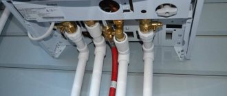
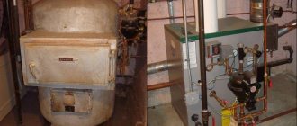
From the author: hello, friends! Piping a heating boiler with polypropylene is done quite often, since these pipes have many advantages. But still, some owners of private houses sometimes have doubts about this.
Polypropylene is a relatively new material. At least it cannot be said that it has been used for centuries. Therefore, sometimes there are concerns about how durable it is, how it can withstand various aggressive conditions - after all, in this case we are talking about working with high temperatures.
It is worth saying right away that all these fears are, in general, groundless. If you choose the right pipes and do the piping correctly, you will get a very high-quality, reliable and durable heating system. Therefore, let's understand the nuances so that all this no longer raises questions for you.
Polypropylene pipes in heating systems
Fittings and pipes made of polypropylene (PPR) are popular due to their low cost and ease of installation. They are not subject to corrosion, have smooth internal walls and serve no less than the 50 years declared by the manufacturer.
There are several types of these pipe products, which differ in technical characteristics and purpose.
In the construction of heating systems, as well as in the installation of hot water supply circuits similar to them in operational parameters, the following is used:
- Pipes marked PN 25. Products with reinforcement made of aluminum foil. Used in systems with nominal pressure up to 2.5 MPa. Operating temperature limit +95º C.
- Pipes marked PN 20. Reinforced version used in DHW branches of double-circuit heating boilers. They will work for the period stated by the manufacturer if the coolant temperature is not higher than +80º C and the pressure is not higher than 2 MPa.
- Pipes marked PN 10. Thin-walled polymer products. They are used if the boiler supplies coolant to the water heated floor system. Operating temperature not higher than +45º C, nominal pressure up to 1 MPa.
Polymer pipes are suitable for all known installation methods: open and hidden. But this material has a high coefficient of thermal expansion. When heated, such products begin to slightly increase in length. This effect is called thermal linear expansion and must be taken into account when constructing pipelines.
The boiler should be tied with polypropylene pipes, which are marked as operating class 5, operating pressure of 4–6 atmospheres and nominal pressure PN of 25 and above
To prevent destruction of polypropylene heating pipelines, compensation loops can be installed. But it’s easier to take multilayer pipes, the reinforcement in which is specifically designed to compensate for this stretching. A layer of foil inside PN 25 polypropylene pipes reduces their thermal elongation by half, and fiberglass by five times.
Image gallery
Photo from
Large diameter PP pipe welding machine
Features of welding wide plastic pipes
Connection of narrow polypropylene pipes
Apparatus for connecting small diameter PP pipes
Simple formulas - for an apartment
Residents of multi-storey buildings can use fairly simple calculation methods that are completely unsuitable for a private home. The simplest calculation of heating radiators is not highly accurate, but it is suitable for apartments with standard ceilings no higher than 2.6 m. Please note that for each room a separate calculation of the number of sections is carried out.
The basis is the statement that heating a square meter of room requires 100 W of radiator thermal power. Accordingly, in order to calculate the amount of heat required for a room, we multiply its area by 100 W. So, for a room with an area of 25 m2, it is necessary to purchase sections with a total power of 2500 W or 2.5 kW. Manufacturers always indicate the heat output of sections on the packaging, for example, 150 W. Surely you already understand what to do next: 2500/150 = 16.6 sections
You should also take into account possible heat loss depending on the location of the room. For example, if this is a room located on the corner of a building, then the thermal power of the batteries can be safely increased by 20% (17 * 1.2 = 20.4 sections); the same number of sections will be needed for a room with a balcony. Please note that if you intend to hide the radiators in a niche or hide them behind a beautiful screen, then you automatically lose up to 20% of the thermal power, which will have to be compensated by the number of sections.
Features of installation of PPR pipelines
When piping a boiler, polypropylene pipes and fittings are connected mainly by cold or hot welding; when connecting to metal pipelines, threaded connections are used. Screwing on is much more convenient, but because of them, assembling the system will cost significantly more.
True, if you want to connect a polypropylene pipeline to a metal counterpart, you cannot do without threaded fittings.
An extensive line of fittings is produced to form linear and nodal connections of polypropylene pipes
“Hot” welding is done with a special apparatus (soldering iron, “iron”). The pipes are heated using a suitable nozzle to a melting temperature of 260 degrees, and then the parts with softened edges are pressed against each other. The result is a reliable and monolithic connection.
Before welding, the foil of reinforced pipes must be cleaned. Otherwise, it will interfere with the connection of polymer products, making the seam fragile. With fiberglass, these unnecessary steps will not be required. It melts easily along with the plastic.
PPR soldering technology is extremely simple, all work can be done with your own hands (+)
Cold welding involves the use of a specialized adhesive composition. In recent years, this method has rarely been used, because the result is not reliable enough.
In heating systems, threaded connections should be sealed with paronite or high-temperature sealant. Do not forget about the fairly high operating temperature of the coolant.
There is one more nuance of using polypropylene for piping a heating boiler. Antifreeze and plastic are a pretty bad combination. It is recommended to use water as a coolant for a system of plastic pipes.
Requirements for a room with two boilers
In the case when the same type of heating sources are selected, the requirements for the furnace are applied to the specific type of fuel used: gas, coal, pallets or electric heating.
The boiler room in the house needs to be treated with due attention
If units operating on different types of energy carriers are selected, the premises must comply with both, and the larger indicator is selected.
Requirements for units using solid fuel:
- The floor area of the combustion room is selected according to the total thermal power of the devices: up to 32 kW, 7.50 m2 is required, up to 62 kW - 13.50 m2, up to 200 kW - 15.0 m2.
- A unit of more than 30 kW is installed in the center of the combustion chamber to ensure reliable circulation of air masses.
- The surface elements of the combustion chamber: floor, walls, ceiling and partitions are made of fire-resistant building materials, using waterproofing protection.
- The boiler is installed on a reliable foundation made of fire-resistant building materials.
- For units up to 30 kW, the requirements for fire resistance of the floor are lower; it is enough to cover it with a steel sheet.
- The supply of solid fuel is stored in a separate dry room, and the daily supply can be located in the boiler room at a distance of at least 1 m from the boiler.
- The furnace room must have a door and windows installed that can provide reliable air circulation three times based on the existing volume of the room.
Requirements for furnace units with gas-fired boilers:
- Gas boilers with a total power of up to 30 kW can be installed in non-residential premises of a house where there are windows and doors that can provide 3 times air circulation.
- When the power of the gas source is more than 30 kW, a separate furnace room is required with a ceiling height of at least 2.5 m and a total area of more than 7.5 m2.
- If this equipment will be installed in a kitchen in which a gas stove operates, then the room must be at least 15 m2.
Selecting a heating system wiring diagram
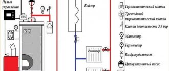
There are several options for lining the boiler with polypropylene. This scheme is selected individually for each house. What is optimal in one building may be ineffective in another.
In addition, heating systems based on the principle of water movement are divided into: forced with a hydraulic pump and gravity (gravity, natural), there is also a classification based on the construction of pipelines. According to their structure, they are single- and double-pipe, collector beam or analogues with closed rings.
Which is better: gravity or pump?
In the gravity circuit, heated water flows from the boiler to the radiators by gravity. A hot coolant that has a high temperature always tends to replace a colder liquid. This heating boiler piping system is the easiest to assemble. In addition to the heater, it contains polypropylene pipes, radiators and an expansion tank.
In the version with top distribution, water, after heating, rises to the highest point - into the expander, and from there it goes down to the batteries. After the heat is released, it returns to the boiler, where it is heated again, then starting a new cycle.
This is how heating is installed in many houses in our country’s villages. Only there is a solid fuel stove. This is the simplest and cheapest way to organize heating for a small cottage. However, it has limitations both in the number of connected radiators and in the distance of the outermost one from the water heater.
The piping scheme with natural water movement is the simplest of all possible options, it has a minimum of nodes and connection points for polypropylene pipes
The compulsory system is more complex and expensive. However, it greatly simplifies the creation of comfortable temperatures in individual rooms. The coolant moves in it due to the stimulation of its movement by the pump.
The choice of polypropylene pipe layout and the boiler itself are closely related. The natural circulation system is energy independent. If the water heater does not require power from the electrical network, then even during power outages the house will be heated.
In a forced circuit, the pump requires a constant power supply to operate. Therefore, it is best to select a boiler for it that is dependent on electricity, which has additional capabilities. But in order to insure against voltage problems, you will have to purchase a backup generator or uninterruptible power supply.
Which heating scheme is better to choose?
There are many ways to route polypropylene pipelines from the boiler to the heating radiators.
But all these schemes are divided into:
- single-pipe;
- two-pipe.
In single-pipe systems, heated water supplied as a coolant is supplied and discharged through one pipe. In two-pipe systems for supplying coolant and return, i.e. to drain cooled water back into the boiler for heating, separate lines are constructed.
According to the method of connecting the working components, heating circuits are divided into:
- tee;
- collector
Tee types can be used for both gravity and forced circulation. The collector circuit can only work if there is a circulation pump.
A single-pipe circuit is obviously cheaper than a two-pipe circuit, but the radiator farthest in the chain from the boiler receives a minimum of thermal energy (+)
The single-pipe method involves laying one looped line and connecting batteries in series to it. In a two-pipe scheme, two independent pipelines with hot water and return flow from the boiler. And radiators are already connected to them.
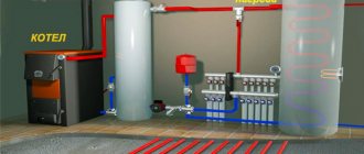
With collector piping, one or two collectors are built into the system, from which separate pipes are routed to each battery. Also, such a distributor allows you to connect a “warm floor” made of the same PPR to the boiler.
Collector wiring makes it possible to create efficient heating systems for houses of large area and different number of storeys (+)
The use of collectors and separate risers for each battery leads to a significant increase in the cost of both design and installation. At the project preparation stage, more complex calculations have to be made. And during assembly, a much larger volume of polypropylene is consumed. But what we get is a system, each part of which can be adjusted to specific conditions and requirements.
Components of the strapping
Which components and elements will be included in the set of heating system components depends on the type of heating system:
- Heating with natural (gravitational) circulation of heated water (coolant) - popularly called “physics” heating;
- Forced circulation – with connection of an asynchronous circulation pump;
- Mixed scheme.
In a scheme with natural water circulation, the set of piping elements will be as follows:
- Heating boiler - after it, the heated coolant rushes up and moves through the pipes, returning to the boiler slightly cooled;
- Heating piping pipes - most often for a “gravity” scheme, metal pipes are used that are larger than plastic pipes, with a diameter of up to 2 inches. The diameter is selected based on the need to minimize coolant resistance for its unhindered circulation;
- Expansion tank - installed at the highest point of the system, and can be open or closed in design;
- Heating devices – radiators, radiators or registers;
- Mayevsky tap - installed on the heating radiator to bleed air;
- Fittings - welded or threaded turns, doubles, tees made of cast iron, brass, bronze, copper or stainless steel, tees, drains and other types of connectors;
The advantage of the “physics” system: easy independent installation, simple circuit, common parts and assemblies, low cost of components.
Disadvantages: large size of components, inertness, insufficiently fast heating of wiring and heating devices. Heating scheme with gravitational water circulation
Polypropylene circuit for different boilers
Most manufacturers of water heaters recommend making the first meter of the pipeline from metal. This is especially true for solid fuel devices with a higher outlet water temperature. When piping, polypropylene should be connected to this outlet, otherwise if the boiler malfunctions, it will suffer a thermal shock and may burst.
Option #1: Gas water heater
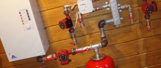
It is recommended to piping a gas boiler with polypropylene using a hydraulic arrow and a manifold. Often, gas models are already equipped with built-in pumps for pumping water. Almost all of them are originally intended for compulsory systems.
The most reliable in terms of safety will be a scheme with circulation equipment for each circuit behind the collector.
In this case, the built-in pump will pressurize a small section of the pipeline from the boiler to the distributor, and then additional pumps will be used. They will bear the main burden of pumping coolant.
You can tie a gas boiler with polypropylene without long metal pipes; the water in such a heater rarely heats up to 75–80 degrees
If the gas boiler has a cast iron heat exchanger, then when piping it into the system, an additional heat accumulator should be installed. It will smooth out sudden changes in water temperature, which have a negative effect on cast iron. If the coolant is heated or cooled abruptly, it may even burst.
When piping a double-circuit device with parallel heating of water for domestic hot water, additional fine and coarse filters will have to be installed on this outlet. They should be mounted at the entrance to the water heater, where cold water is supplied.
Option #2: Solid fuel model
The main feature of a solid fuel boiler is its inertness when the fuel supply is stopped. Until everything in the firebox burns out completely, it will continue to heat the coolant. And this can have a detrimental effect on polypropylene.
When piping a solid fuel boiler, only metal pipes should be connected to it immediately, and polypropylene pipes can only be inserted after a meter and a half. In addition to this, it is necessary to provide a backup supply of cold water for emergency cooling of the heat exchanger, as well as its discharge to the sewer.
The section of the pipeline from the solid fuel boiler to the collector should be made of metal, and then you can tie it with polypropylene - this is the only way to protect the plastic pipes from overheating
If the system is built on forced circulation, then it will be necessary to install an uninterruptible power supply for the pump. Water must constantly remove heat from the firebox where solid fuel burns, even during power outages.
In addition to it, you can make a small gravity circuit or equip all batteries with bypasses to turn off individual sections of the system. In case of accidents, this will allow you to repair the damaged section while the heating is running.
The solid fuel boiler must be covered with a protective casing, which limits the spread of heat from the walls of the firebox into the boiler room. But even if it is present, the manifold and plastic pipes should be removed away from the stove.
Option #3: Oil and Electric Heaters
The exhaust or diesel boiler is wrapped with polypropylene according to a scheme identical to its solid fuel counterpart. The polymer must be removed from it as far as possible.
When piping an electric PPR boiler, you don’t have to worry about pipe ruptures; it has an automatic safety device that prevents the water from boiling.
Heating the coolant in an electric water heater to critical temperatures for polypropylene is practically impossible. When the voltage goes out, it simply stops working. In this case, the pipes are protected from hydraulic shocks by a hydraulic accumulator and valves to relieve excess pressure.
How is such equipment connected?
The general installation scheme of heating boilers consists of the following series of stages:
- installation of distribution combs;
- installation of appropriate pumping circuits for each consumer;
- installation of safety equipment;
- installation of an expansion tank;
- installation of shut-off valves;
- connection of the boiler with the supply and return circuits;
- filling the circuits with coolant;
- testing equipment and checking its operation.
In practice, everything depends on the power of the equipment, the number of consumers, the design features of the boiler, etc. It should be noted that quite high requirements are placed on the piping of pellet boilers. Firstly, because the moisture content of the fuel must remain acceptably low, and secondly, because both the fuel and the coolant are heated to very high temperatures. Poor-quality piping can lead to the fact that the operating conditions of the equipment will be violated, and the boiler will quickly fail.
In accordance with fire safety standards, it is recommended to use non-flammable metal pipelines for piping pellet boilers. The use of polypropylene structures in practice is not only dangerous, but also unprofitable, since the temperature of the coolant at the boiler outlet often exceeds the performance indicators of polymer materials. As a result, the pipelines will have to be replaced within a couple of years.
A pellet boiler is a rather complex device. Experts strongly do not recommend that inexperienced beginners install and wire such devices. However, knowledge of the main stages of tying and some of the nuances of this process will allow you to effectively monitor the work of the invited team of installers.
The diagram shows one of the options for piping a pellet heating boiler: 1 - MK pump; 2 - mixing valve MK; 3 — pump TK1; 4 — mixing valve TK1; 5 - water recirculation in TK1; 6 — pump TK2; 7 — mixing valve TK2; 8 — water recirculation in TK2; 9 - DHW pump; 10 - DHW heat exchanger; 11 - supply of running water to the hot water supply
To piping a pellet boiler, you must:
- install the boiler;
- connect the appropriate burner (if a combined boiler model is used);
- install a pellet hopper;
- connect the auger for fuel supply;
- connect the automatic boiler control panel.
After this you should do:
- Installation of a safety group on the boiler supply, which includes a pressure gauge, automatic air vent and relief valve.
- Installation of a thermal valve sensor, if provided for by the design of the model;
- Installation of a chimney whose diameter and height meet the technical requirements.
- Installation of a system of devices to maintain reverse flow: two pressure gauges for supply and return, a circulation pump and a thermal head.
- If there is a high probability of sudden power outages, it is recommended to supplement the system with a suitable UPS model.
Reverse flow support allows you to control the heating level of the coolant before it enters the system. Until the return temperature reaches the required level (usually 60 degrees and above), the coolant will remain within the small circulation circle. Only when the coolant is heated to the required level will the thermal head open and cold coolant begins to flow through it, and hot coolant will begin to circulate in the main circle.
Under no circumstances should you use a pellet boiler with a low coolant temperature. A temperature of 55 degrees is the so-called “dew point”, upon reaching which a significant amount of condensation occurs. As a result, the volume of soot in the chimney, as well as on the heat exchanger, can increase significantly. The equipment will require additional maintenance efforts, and its power will noticeably decrease.
This is what the combustion chamber of a pellet heating boiler looks like after exposure to excessive amounts of condensate that appears due to errors in the installation of the recirculation system
The process of piping a combined pellet boiler is presented in detail in the video:
Many manufacturers of pellet boilers recommend supplementing the design with a special storage tank, which allows you to accumulate heat. Fuel savings can reach 20-30%. In addition, the use of a storage tank allows you to avoid overheating of the boiler and achieve the highest possible efficiency.
Radiators
The piping of heating radiators, as well as boilers, is done with polypropylene. When used, the pipe system is sealed and reliable.
Strapping options
There are two radiator piping schemes. With the single-pipe type, all radiators are connected in series; temperature adjustment is possible only when inserted into the bypass system. With the two-pipe method, the coolant is supplied more efficiently, it does not cool down as much and the load on the boiler is reduced.
The pipes must be connected directly to the radiator so that the coolant flow passes through the entire internal surface without forming stagnation zones.
IMPORTANT! Pipes to the batteries should be connected through taps, so that in case of damage to the radiator, the defective section is excluded from the overall system
Components of the strapping
Which components and elements will be included in the set of heating system components depends on the type of heating system:
- Heating with natural (gravitational) circulation of heated water (coolant) - popularly called “physics” heating;
- Forced circulation – with connection of an asynchronous circulation pump;
- Mixed scheme.
Set of piping elements
In a scheme with natural water circulation, the set of piping elements will be as follows:
- Heating boiler - after it, the heated coolant rushes up and moves through the pipes, returning to the boiler slightly cooled;
- Heating piping pipes - most often for a “gravity” scheme, metal pipes are used that are larger than plastic pipes, with a diameter of up to 2 inches. The diameter is selected based on the need to minimize coolant resistance for its unhindered circulation;
- Expansion tank - installed at the highest point of the system, and can be open or closed in design;
- Heating devices – radiators, radiators or registers;
- Mayevsky tap - installed on the heating radiator to bleed air;
- Fittings - welded or threaded turns, doubles, tees made of cast iron, brass, bronze, copper or stainless steel, tees, drains and other types of connectors;
The advantage of the “physics” system: easy independent installation, simple circuit, common parts and assemblies, low cost of components.
Disadvantages: large size of components, inertness, insufficiently fast heating of wiring and heating devices. Heating scheme with gravitational water circulation
Christmas tree fittings - tee type
The tee-type fountain fittings have two tees: the upper one is the working one, the lower one is the backup one.
The tee-type Christmas tree fittings have nominal bores of 50 and 90 mm.
The tee-type fountain fittings have two tees: the upper one is working, the lower one is a backup one, which is used only during repair or replacement of the upper one. Reinforcement of this type has a large height (up to 5 m from the ground surface), is inconvenient to maintain, and is unbalanced. It is used in particularly difficult well operating conditions - in the presence of solid suspensions in the gas flow that cause abrasive wear of equipment, gaseous or liquid corrosive agents (carbon dioxide, hydrogen sulfide, propionic, butyric or other fatty acids), with sharp fluctuations in pressure and temperature.
The wellhead is equipped with a special twin tee-type Christmas tree with two-string flow lines for each formation. There are a number of modifications of well equipment according to the fountain-gushing scheme, adapted for various operating conditions.
| Scheme of cross fountain fittings. |
In sand production wells, a tee-type X-mas tree is used. Instead of a cross 7, a tee (not shown in the figure) with a spare flow line is installed on the central valve 6, then an intermediate valve and a tee with a working flow line.
The well's surface equipment is a special double X-mas tree of the tee type with nominal bores of 50 and 40 mm in diameter and with two-string discharges for each formation (Fig. XIII. The fittings are designed for an operating pressure of 20 0 MPa. Equipment with parallel placement of tubing pipes is used in wells with a production casing with a diameter of 168 mm or more.
Deep gas-condensate wells are equipped with an AF-60-300 tee-type (two-string) Xmas tree in a flanged design, designed for GOO am test pressure and 300 am operating pressure.
To test a well equipped with a tee-type X-mas tree, a line must be laid from the bottom string of the valve for installing a diaphragm critical flow meter (prover), and a purge line must be laid from the top string.
To test a well equipped with a tee-type Xmas tree, a line for installing the prover must be laid from the bottom string of the fixture, and a purge line must be laid from the top string. If the fountain fittings are of the cross type, then a line must be laid from one string, and a blow-off line from the other.
In accordance with GOST 13846 - 89, tee-type Christmas tree fittings are produced for operating pressures of 14, 21, 35, 70 and 105 MPa. Christmas trees with bore diameters of 100 - 150 mm are designed for high-yield oil and gas wells.
After completing the well killing work, the AFT2 - 21/2x320 tee type Xmas tree should be dismantled, having previously disconnected it from the pipeline. At the wellhead, install a preventer installation in accordance with Scheme 2 according to GOST 13862 - 90 and remove the lift string from the well, inspect the pumping and compressor pipes.
| Wellhead piping and location of surface equipment during well development in the Stavropolneftegaz association. |
When developing wells with a depth of 1000 - 1500 m, a Christmas tree with a bore of 50 mm is used - 1AFT50, 2AFT50, etc., in Fig. IV.10 shows a diagram of the piping of the wellhead with the 2AFT50 Xmas tree and the location of ground equipment during the development and exploration of wells in the Pyatigorsk geological prospecting expedition of the Stavropolneftegaz association. At the wellhead, a tee-type christmas tree with a pressure of 12–5 MPa is installed. The upper string is directed to the gas separator and to the torch, and the lower string is directed only to the torch. From the gas separator, the liquid enters the measuring tank, and the gas, after measuring using a prover, goes to the torch. The upper string contains a fitting chamber, a rock collector, a pressure gauge and a pocket for a thermometer. The gas separator is installed at a distance of 50 m from the Christmas tree fittings.
| Wellhead piping and location of surface equipment during well development in the Stavropolneftegaz association. |
Recycling
In a parallel position to the main radiator heating circuit or a small circuit in the area from the boiler to the hydraulic switch, a low-temperature circuit is installed. It contains a bypass and a three-way thermostatic valve. Thanks to the pump, water constantly circulates inside the underfloor heating pipes.
To select new portions of hot coolant from the supply pipe when the temperature inside the return pipe drops, a three-way mixer is used. It can be replaced with a simple thermostatic valve equipped with a remote capillary-type temperature sensor or an electric thermocouple. The sensor is installed in a niche on the return line of the heated floor. The valve is activated when the coolant temperature drops.
Recommended materials
The choice of material is of utmost importance. The pipeline must be reliable, practical and inexpensive, as well as easy to install and not subject to corrosion.
Polypropylene
The most commonly used pipelines are polypropylene. This material is resistant to aggressive environmental influences and plaque formation.
Polypropylene pipes are connected to each other by soldering, and not with fittings like metal ones. This results in a strong monolithic connection that eliminates the possibility of leaks.
In addition, most manufacturers provide a guarantee of up to 40 years on their products. In this case, the pressure in the system can increase to 25 bar, and the temperature - up to 95°C. This means that the heating boiler piping will not only be as reliable as possible, but durable.
Metal eyeliner
However, it should be taken into account that the gas supply to the water heater must be tight!
The best option is a metal pipe and a metal pipe or “American”. Only a paronite gasket can be used as a seal. It is paronite that is most often used when installing boilers, because this material is not flammable, holds its shape perfectly and maintains the tightness of the connection for a long time. Paronite is a mixture of asbestos fibers, rubber and mineral additives.
Design
The production of fittings, according to GOST 13846-84, involves the use of tee and cross type schemes.
The device consists of:
data-ad-client=»ca-pub-8514915293567855″ data-ad-slot=»1955705077″>
- pipe head;
- fountain tree;
- manually operated locking devices;
- chokes.
The pipe head is used to hang several rows of tubing and seal them. In addition, the pipe head takes part in technological operations, which include: development, operation and repair of the well.
Hanging of columns is carried out (on a thread):
- if a single-row elevator - on the coil thread;
- if there is a two-row elevator: the inner column is on the thread of the coil, the outer column is on the thread of the crosspiece of the pipe head.
The pipe head requires replacement of its side valves. This process is carried out using special blind plugs, which are installed in the threaded holes of the housing.
Shut-off devices on fountain fittings with manual control
Christmas tree functions:
- directs product to the flow line;
- takes part in the installation of special devices;
- measurements of pressure and temperature of the environment;
- lowering downhole instruments for pipe cleaning.
Shut-off devices are presented in the form of straight-through plug valves and direct-flow valves with a lubricant supply. Their main purpose is to cover passage holes.
Column heads serve as casing hanger, sealing and pressure control between pipe strings. to menu
Technical requirements for design
GOST 13846-89 defines a Christmas tree as a device designed to seal wells, shut off the medium and direct it to the manifold, and carry out other technological operations.
According to GOST 16350-80, fountain fittings can be used in temperate and cold macroclimatic regions. Placement is carried out according to category 1 (GOST 15150-69).
Optimal ambient temperature: from -60ºC to +40ºC.
High-quality fittings are durable and can withstand atmospheric loads
GOST 51365-2009 established the use of a certain material and the level of technical requirements that are most suitable for operating conditions.
The production of parts can be designed according to individual orders, taking into account that all operating conditions and the choice of component materials will comply with established standards. to menu
Designation AFK
- AF – fountain fittings;
- K – method of hanging the pipeline according to GOST 13846-84;
- n – scheme according to GOST 13846-84 (n = 1-6);
- E – cable entry;
- 65×21 – nominal diameter and working pressure in MPa;
- HL – climatic versions of the product;
- K1 – corrosion resistance category.
Typical schemes according to GOST 13846-89:
- AF1, AFK 1;
- AF2, AFK 2;
- AF3, AFK 3;
- AF4, AFK 4;
- AF5, AFK 5;
- AF6, AFK 6.
to menu
Operating principle
A hydraulic heating arrow in cross-section is a section of a hollow pipe with a square cross-section. This device works very simply. The air is separated and eliminated by an automatic air vent. The heating system is divided into 2 different circuits - large and small. The small circuit represents the boiler/water gun, and the large circuit represents the boiler/water gun/consumer.
When the heating boiler provides an amount of coolant that is equal to its consumption, then the liquid flows only horizontally in the hydraulic arrow. If this balance is disturbed, then the coolant flows into the small circuit, after which the temperature in front of the boiler increases. The boiler reacts to such changes by turning off, and the coolant continues to move until the temperature drops to a certain value. Then the boiler turns on again. Thus, the hydraulic separator in the heating system ensures a balance between the boiler and boiler room circuits, while guaranteeing the independent operation of each individual circuit.
How to achieve natural circulation?
If the piping scheme of a solid fuel boiler with a circulation pump can be almost any (with bottom, top, diagonal connection of radiators, single-pipe or two-pipe), then to ensure natural circulation it is necessary to follow some rules:
- The flow diameter of the pipe should ideally be at least 38 mm or one and a half inches. For comparison, central heating systems use a steel pipe with an internal diameter of 16-20 mm
- The boiler should be at the lowest point, the expansion tank at the highest
- The entire pipeline must be installed at a slope of 5 mm per 1 linear meter of pipe. That is, the level difference between the beginning and end of a ten-meter section of pipe should be at least 5 cm
- Heating radiators cannot be mounted on transition pipes with a reduced flow diameter
A lot of photos and videos on piping solid fuel boilers with natural circulation can be found on the Internet, but we hasten to warn you against trying to do this work yourself. If there is no or difficult circulation in the system, the heating unit will overheat, its efficiency will be low, and fuel costs will be high. Even more dangerous is the lack of normal draft in the chimney. Our specialists will install the boiler and its piping to ensure high performance properties of the system.
Types (with examples of models)
They are divided according to different parameters.
By fuel type
- Heating equipment using only pellets as fuel. For the successful operation of such a unit, stable and timely supplies of fuel will be required.
Example: pellet boiler Roteks-15
- Conditionally combined. The specially shaped firebox makes it possible to burn, in addition to pellets, other types (briquettes or firewood). Burning alternative fuel in a wood-fired pellet boiler is an emergency function. Constant operation in this mode will lead to failure of the pellet wood boiler.
Model example: Faci 15 pellet boiler
- Pellet combined. They have built-in special combustion chambers designed to use their type of fuel. Although such heating devices are universal, they have a couple of disadvantages: large sizes and a very high price.
Model example: STROPUVA S20P
By type of fuel supply to the boiler
- Automatic. Automation of the process is the main advantage of such boilers. To calculate the required power and configure such an automated pellet boiler, the services of specialists are required.
Example: Termodinamik EKY/S 100
- Semi-automatic. The power is set manually by the regulator, and subsequently the granules are supplied automatically.
Pellet boiler UNITECH Multi 15
- Mechanical loading of granules. Such a unit requires the constant presence of a person to periodically load granules.
STROPUVA MINI S8P
By purpose
- Heating fluid (water). Most often, they are located in basements and have quite serious dimensions; their appearance is purely utilitarian.
Pellet boiler SIME SOLIDA 8
- Convection oven-fireplace for heating the surrounding atmosphere. It is installed in the living room, has compact dimensions and a pleasant design.
Pellet fireplace Termal-10 BASIC
- Hybrid heating schemes. They combine heating using a water coolant with direct heating of the surrounding air at the location. Externally they are very similar to fireplace stoves. Some models are equipped with a cooking surface and, in some cases, an oven.
Heating boiler Kupper OVK 10 with pellet burner APG25
By burner type
- Flare. They are most widespread and are most often used in private homes. Low power burners for small combustion chambers are simple and reliable, and are also quite easy to set up. The downside to them is the unidirectionality of the flare fire, which leads to localized heating of the boiler wall. Very demanding on the quality of granules.
Model example - Lavoro LF 42
- Volumetric combustion. Such burners have greater power and are used in industrial equipment, but they have also found their niche in ordinary boilers. A huge advantage of such burners is their undemanding quality of granules, but their use has led to a significant increase in the weight of the device.
Representative - Radijator COMPACT 20
- Fireplace. In such a boiler, pellets falling into the bowl burn. This is the safest type of burner, and the operation of heating equipment of this type does not create much noise. The downside is the paucity of adjustment settings and demands on the quality of the granules. This is the most economical pellet boiler in the entire line.
Pellet fireplace Termal-6
This is interesting: Finishing the facade of a private house with siding: let’s describe the main thing
Safety valves
They are not used when the heating system is open. The purpose of the valve is to protect the boiler from damage in the event of a sudden increase in pressure.
Usually the valve is forgotten or a model or safety group with different characteristics is installed. When the valve responds, some of the water flows out of the system, providing pressure relief and protection. You should not insert the drain tube into the sewer, since the reason for the decrease in pressure will not be clear. You can get by with a funnel. By the way, there is no need to throw the septic tank into the coolant.
Air vent
. The part must be installed immediately after installing the boiler to avoid “airing”. Often they simply forget to open it. This is also typical for wall-mounted options with a factory function. By the way, the circulation pump is also ventilated.
The air vent must stand strictly vertically upward. When it starts to leak, there is a shut-off valve in front of it, so replacing it with a new one will take a couple of minutes.
Circulation pump
. The pump will operate properly only when the axis is in a horizontal position, and this position will significantly extend the “life” of the bearings.
It is advisable to protect the mechanism from dirt and debris from the outside. Strainers sold separately
Radiators.
Disadvantages when connecting a panel radiator to the coolant. The radiator design involves connecting the supply pipe to the internal vent, located almost in the center, and to the outermost one - in the return pipe. The reverse connection order will reduce the heat transfer of the radiator by half. By the way, decorative screens disrupt heat transfer by 10-20%.
Proper installation and correct power calculations will help create maximum comfort for living in a country house at any time of the year.
Purpose of fountain fittings
Devices of this class are responsible for solving the following engineering and technical problems:
- ensuring well sealing;
- diversion of products transported through the pipeline system;
- to adjust and maintain well flow;
- when providing access to the well bottom;
- to ensure sampling without stopping production processes.
Products of this class are used at high pressures arising under the influence of loads. Fittings are used when there is a possibility of exposure to aggressive environments inside the well. Quite often it is used if the liquid contains a large number of impurities of different origins and sizes.
When using such a system, it is necessary to take into account that this equipment must have a long service life and the necessary margin of safety. The main consumers of these products are enterprises engaged in the production and transportation of hydrocarbons, as well as the construction of pipeline transport systems.
Primary-secondary rings
For boilers with a power of 50 kW or more or a group of boilers that are intended for heating and hot water supply to large houses, a primary-secondary ring scheme is used. The primary ring consists of boilers - heat generators, secondary rings - heat consumers. Moreover, consumers can be installed on the forward branch and be high-temperature, or on the reverse branch and be called low-temperature.
To ensure that there are no hydraulic distortions in the system and to separate the circuits, a hydraulic separator (arrow) is installed between the primary and secondary circulation rings. It also protects the boiler heat exchanger from hydraulic shocks.
If the house is large, then after the separator a collector (comb) is installed. For the system to work, you need to calculate the diameter of the arrow. The diameter is selected based on the maximum productivity (flow) of water and flow speed (not higher than 0.2 m/s) or as a derivative of the boiler power, taking into account the temperature gradient (recommended value Δt - 10 ° C).
Formulas for calculations:
- G—maximum flow rate, m 3 /h;
- w is the speed of water through the cross section of the arrow, m/s.
- P—boiler power, kW;
- w—water velocity through the cross section of the arrow, m/s;
- Δt—temperature gradient, °C.
Electric and diesel heat generators
Connecting a diesel fuel boiler to the radiator system is identical to piping gas-using installations. Reason: a diesel unit operates on a similar principle - an electronically controlled burner heats the heat exchanger with a flame, maintaining the set coolant temperature.
Electric boilers, in which the water is heated by heating elements, an induction core, or through the electrolysis of salts, are also connected directly to the heating. Automation located in an electrical cabinet connected to the network according to the electrical diagram provided is responsible for maintaining temperature and safety. Other connection options are shown in a separate publication on the installation of electric heating boilers.
Wall-mounted mini-boiler rooms equipped with tubular heaters are intended only for closed heating systems. To work with gravity wiring, you will need an electrode or induction unit, which is tied according to the standard scheme:
