As is known, the power supply system for the end consumer is built according to the schemes recommended by the Electrical Installation Rules (PUE). A power cable is supplied to the facility, and further wiring occurs in the distribution panel. For ease of installation and organization of power supply lines, inputs with different values are combined into contact groups. A bus with a phase, a zero bus is a contact block in which there is the ability to reliably connect several conductors to power electrical installations.
Requirements for the zero bus
- For a group network, the bus must be a single conductor, without the possibility of switching between its parts.
- The resistance should be the same along the entire length.
- Within one group line, it is allowed to combine conductors PE (protective grounding) and N (working zero).
In this case, after dividing the PEN input into PE and N buses, end consumers are connected to different buses.Important! Using one bus to connect the working zero and grounding is prohibited! This is a fundamental issue, it is necessary to understand the difference between splitting and merging PE and N.
From the moment of separation, the ground and neutral lines can be laid in one power cable, but the conductors must be insulated.
- Regardless of the connection method (three-phase or single-phase), the cross-section of the neutral conductor must correspond to the cross-section of any of the phase conductors. The same requirement applies to the cross-section of the tire itself.
- The cross-section of the connecting wires from the bus to the final electrical installation cannot be higher than the cross-section of the input power wire.
- If the bus is a structure with holes for connecting conductors, the actual cross-section is considered to be the geometric parameters in the thinnest part.
- There are no requirements for the mandatory production of a zero working tire from a specific metal. However, in practice, copper or brass is used. When calculating the cross-section of aluminum busbars in relation to copper busbars, a coefficient of 1.52 is applied.
For convenience, we will consider a single-phase circuit, which is used in most apartments in multi-storey buildings. Two main lines: phase and zero, are always present. They are inserted into the meter (electricity meter), and at the output they become available for further wiring. Depending on the system used, either only a zero bus or a zero and ground bus can be installed.
Copper ground bus
The copper-based grounding bus refers to conductors with low resistance values.
The standard element is fixed to the body of the electrical panel, and also easily withstands thermal loads and high voltage during a short circuit. One of the most popular options is a grounding copper strip, made using high-quality electrical copper of the “M-1” grade.
Copper grounding bar
The protective element is manufactured in accordance with GOST 434-78, and is characterized by a high level of alloy purity with a solid metal content of 99% or more.
Due to the high quality of the source material, the copper busbar is designed for operation in operating temperatures ranging from minus 55°C to plus 280°C, with a maximum operating voltage of 1000 W.
Established standards regulate the marking of copper grounding bars with mandatory indication of thickness, width and length.
Tire installation option
Copper grounding bars can be used not only indoors, but also outdoors, due to the following performance characteristics:
- high level of thermal conductivity;
- high level of electrical conductivity;
- low resistivity values;
- resistance to corrosive changes.
When installed externally, copper grounding bars provide effective lightning protection, so they are often mounted on lightning rods.
It is very important to install copper ground bars in regions where there is extremely frequent and high lightning activity.
Design features
First, let's look at the design of the comb. The product consists of a copper plate placed in plastic insulation that does not support combustion. Special leads extend from this plate, thanks to which the machines in the panel are connected. The number of plates corresponds to the number of poles.
Please note that there are combs with pitches of 18 and 27 mm. The first ones are intended for switching AVs with a width equal to one module. Accordingly, 27 mm is a width of 1.5 modules
Pay attention to this point when choosing a distribution bus for your own conditions!
Based on the number of poles, connecting busbars are divided into single-pole, two-pole, three-pole and four-pole. Each design option has its own purpose. For example, a single-pole comb is used to connect a single-phase circuit breaker, and a four-pole comb, respectively, is used to install three-phase RCDs with 4 poles (three phases and zero).
The number of taps can be from 12 to 60, so the use of combs to connect two electrical machines is not a rational solution. It is advisable to use a distribution bus when assembling large panels.
The taps themselves can be pin (marked pin) or fork (fork). The former are used much more often, because Fork outlets are not suitable for all machines; they require a special clamp.
The last design feature that I would like to talk about is the cross-section of the bends. As a rule, taps are made with a cross-section of 16 mm2, which is quite enough to withstand a current load of 63 A.
Types of bends
There are two types of outlet contacts included in the connecting combs.
- Bends made in the form of pins and designated as “Pin”. They are used very often because they fit most automatic devices.
- Fork branches marked with the “Fork” icon.
The second type of contact is used much less frequently, since its installation requires a special clamp, which is not available for all connected AVs. The cross-section of the outlet pins is selected in such a way that it is sufficient to work with load currents up to 63 Amps inclusive.
When choosing single-phase busbars, as well as any other dimensions that differ in the type of taps, you will need to take into account a number of design features. For each class of connected devices, only a certain bus sample is suitable. When they try to install a connecting comb whose taps do not correspond to a given device, they may simply not fit completely into the sockets. In this case, some part of the bus plane remains open, which poses a threat to users and installers.
As an example, ABB brand machines are given, the body of which is available in two versions: S200 and a simpler model – S200L. For the first of these samples, a tire designated PSH is suitable, and for the S200L a different type of tire, PS, will be required.
Chinese combs with standard bends may not fit the step size at all, which makes them impossible to use. Experts advise not to skimp on the quality of these products and to purchase only after consultation with sales managers.
Metals used in tire production
Depending on the purpose and required operating parameters, the following can be used for the manufacture of conductors:
- copper;
- aluminum;
- steel;
- steel-aluminum - a steel core covered with a layer of aluminum wires.
The advantages of aluminum tires include anti-corrosion resistance, excellent electrical conductivity, low weight and reasonable cost. For their manufacture, low-alloy aluminum alloys with a low content of silicon and magnesium are used to improve the ductility and strength of the metal.
Copper buses with a copper content of up to 99% are in no way inferior to aluminum ones, but are less widespread due to their relatively high cost.
Zero bus
Zero tire on DIN rail
The connection of grounding and neutral working conductors is carried out using a zero bus. Its design consists of a conductive core and a plastic base, which is mounted on a DIN rail. The core is made of special electrical copper or brass. The design of the conductive element has holes and clamping bolts. Their presence allows for accurate and safe cabling in switchgear units. Models of zero busbars are made in different lengths, which allows you to make the required number of mounting holes in the core. Their main area of application is AC or DC networks designed for operating voltages up to 400V.
Thanks to the use of a zero bus it will be possible to:
- increase the efficiency of the automatic protective devices used;
- create simultaneously several points for connecting loads to the neutral conductor;
- carefully and safely separate neutral and working conductors;
- perform visible grounding using a plastic device with a cover to protect the terminals;
- install a single circuit from the grounding point to each load.
Installation of the zero bus is carried out directly inside the electrical panel or on a metal rail using a bolted connection. There are open and closed installation methods. The first option is provided for electrical cabinets with a closed structure, which prevents unauthorized persons from accessing the internal contents. Closed installation is optimal for networks to which expensive, energy-intensive equipment is connected - machines and mechanisms, power tools, etc.
What does an electrical panel consist of?
The input cable is connected to the electrical panel through holes in the housing, then connections are made to the electrical equipment in accordance with the diagram. For example, when assembling a switchboard, the power cable is connected to the input circuit breaker, and the corresponding equipment that belongs to each consumer group is connected to it.
Inside a modern home electrical panel there is a large number of different switching and protective devices and other types of equipment, including:
- metering device (electricity meter).
- automatic switches (input or disconnecting groups and individual consumers);
- RCDs and automatic devices;
- timers;
- voltage relay;
- phase control relay;
- other automation.
The electrical panel body must be grounded, as well as its metal doors and other live parts. To restrict access by unauthorized persons and prevent electric shock, it must be locked with a key.
Design features
Upon closer examination of the design, you will notice that it consists of a conductive core and a base made of plastic, which is designed for installation on a DIN rail.
The photo shows the appearance of the NS:
The current-carrying core contains holes and clamping bolts for fixing the conductors in it, as well as for neat and safe wiring of conductors N inside the switchgear. NS differ from each other in both the installation method (housing) and the number of mounting holes, respectively, in length.
To ensure a high-quality connection, as well as simplify further maintenance, the bus is made of a single conductive element of sufficient size made of electrical copper or brass. With a different number of bolt terminals to which neutral (N) conductors are connected.
A distinction is made between ground buses in a housing and grounding buses without a housing; the externally conductive elements are identical. The neutral bus is made in a housing or an insulator is installed. For the correct functioning of differential protection devices, it is necessary to connect them correctly, and to separate the conductors N from PE in the distribution board. In the case of a metal shield, this can only be done by isolating the neutral conductor from the housing.
Create the perfect atmosphere
Any electrical device is sensitive to the state of the environment. At high temperatures, equipment overheats; at low temperatures, its electronic components freeze. High humidity and condensation promote corrosion and affect the stability of the entire system. In conditions where many devices operate in a confined cabinet space, the importance of the microclimate increases greatly.
Creating ideal conditions for the equipment inside the housing is achieved using special microclimate control devices.
Heaters and fans from EKF will help maintain the desired temperature and protect against condensation. These are reliable actuators, the operation of which can be easily controlled using compact thermostats and hygrostats mounted on a DIN rail. The thermostat monitors the temperature and sends commands to the heater or fan if it falls outside the set limits. Using a similar principle, a hygrostat monitors the maintenance of a fixed level of humidity in the cabinet.
If the operating conditions of the cabinet require the active use of both devices, then you should install a device in which the thermostat and EKF hygrostat are combined in one housing. It will save space and increase ease of management.
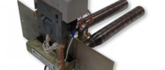
Massive distribution cabinets are designed for equipment that will be used for a long time at a specific facility. But often during construction or renovation it is necessary to organize temporary power for power tools or lighting fixtures. For these purposes, the Basic line produces a box with a step-down transformer YaTP, or as this device is sometimes incorrectly called a YaTP shield. By the way, if during such work you have to think about how to secure the cables, we recommend using a metal clamp - a reliable fastener for heavy communication elements.
Installation Rules
Installation of the simplest terminal to the panel is carried out in a closed or open way. The first option prevents malicious damage to the bus of powerful or important devices, the second method is applicable if there is no risk of damage to the device. Zero blocks with screw connections are fixed to the distribution panel on a DIN rail; additional insulation for grounding is not provided.
The cross-section of neutral and phase conductors is the same. A similar requirement applies to tire parameters: the actual cross-section is considered to be the size of the thinnest sections. When combining a group of ground and neutral conductors, end consumers, after dividing the “PEN” input, are connected to different buses: PE and N.
Connecting single-phase devices
Single-phase connection is the simplest. It is used for single-pole machines. The procedure is as follows:
- All protection devices are installed in a row. This requires a DIN rail.
- For each individual device, the screws in the terminal blocks are loosened to a certain point. This is done from the top side.
- One single-pole bus is inserted into the terminal blocks of circuit breakers. The pitch of its teeth should be 17.5 mm.
- The screws are tightened. The tightening is tight enough to securely fix the tire pins.
Zero bus: types, what it is needed for
As is known, the power supply system for the end consumer is built according to the schemes recommended by the Electrical Installation Rules (PUE). A power cable is supplied to the facility, and further wiring occurs in the distribution panel.
For ease of installation and organization of power supply lines, inputs with different values are combined into contact groups.
A bus with a phase, a zero bus is a contact block in which there is the ability to reliably connect several conductors to power electrical installations.
Requirements for the zero bus
For a group network, the bus must be a single conductor, without the possibility of switching between its parts. The resistance should be the same along the entire length. Within one group line, it is allowed to combine conductors PE (protective grounding) and N (working zero). Moreover, after dividing the PEN input into PE and N buses, end consumers are connected to different buses. Important! Using one bus to connect the working zero and grounding is prohibited! This is a fundamental issue, it is necessary to understand the difference between separation and combination of PE and N. From the moment of separation, the ground and neutral lines can be laid in the same power cable, but the conductors must be insulated. Regardless of the connection method (three-phase or single-phase), the cross-section of the neutral conductor must correspond to the cross-section of any of the phase conductors. The same requirement applies to the cross-section of the tire itself. The cross-section of the connecting wires from the bus to the final electrical installation cannot be higher than the cross-section of the input power wire. If the bus is a structure with holes for connecting conductors, the actual cross-section is considered to be the geometric parameters in the thinnest part. There are no requirements for the mandatory production of a zero working tire from a specific metal
However, in practice, copper or brass is used. When calculating the cross-section of aluminum busbars in relation to copper busbars, a coefficient of 1.52 is applied.
For convenience, we will consider a single-phase circuit, which is used in most apartments in multi-storey buildings. Two main lines: phase and zero, are always present. They are inserted into the meter (electricity meter), and at the output they become available for further wiring. Depending on the system used, either only a zero bus or a zero and ground bus can be installed.
Main stage
After cutting off the excess leads and placing the existing parts in their places, the screws responsible for pressing the contact terminals are secured. The reliability of the connection and the further safety of operation of the switchboard, as well as all its working units and connections, depend on the strength and quality of the clamp. Power is supplied to one edge of the comb, after which alternate connections of consumers are allowed. Then you need to make sure that each connection is correct and activate the power supply to the panel. Installation is now complete.
Benefits of using busbar trunking
An electrical bus is more convenient to use than a group of wires
The use of busbars in electrics instead of cable products provides significant savings in material, energy and labor resources:
- Installation takes 2 times less time than cable laying.
- Service life – up to 30 years without the need for complex maintenance.
- The flexible configuration allows for high-quality and safe installation of the network, depending on the route it runs.
- The busbar has a more aesthetic appearance than group wiring.
- Shielding the conductor eliminates the impact of the electromagnetic field on nearby office equipment.
- The design is fireproof and meets safety requirements for IP55 protection level.
Online home handyman assistant
When operating an electrical network of 400 volts, one cannot do without special protection - grounding conductors and working zeros, which are connected through the zero bus. Without it, assembling a complete electrical panel that meets all safety parameters is impossible, so it is important for every owner of a high-voltage line to know the details of installing the zero bus with their own hands.
More details about the appointment
Using a grounding zero bus in the wiring system allows you to solve many important issues:
- Creation of several points to share the total load from the main input to the neutral conductor.
- “Opening” the grounding mechanism through the use of a transparent cover in the design that protects the terminals.
- Increasing the efficiency and performance of automatic protection devices.
- Ensuring line continuity from direct grounding to the output point.
- Saving space in the panel, since there will be no need to place several single tires.
- Separation of neutral and phase wires.
In general, the zero bus allows you to raise the security of the network to a qualitatively new level, however, its use and connection must be as competent as possible, therefore special requirements are imposed on the installation of this element of the electrical network.
Typical errors
Among the typical mistakes that inexperienced electricians or amateurs make, there are three main points:
- Purchasing and using a comb that does not match the number of inputs and poles of the device being aggregated.
- The use of a connecting bus for automatic circuit breakers (3ph) only for a pair of circuit breakers in cases where its power is sufficient to service a whole set of protective units.
- Connecting an element with a maximum current load of 63 A to a more powerful line.
Characteristics
When choosing the necessary zero buses, it is worth presenting clear requirements for the design. The main thing is the cross-section of the wire. Guided by the clear rule “the cross-section of the wire does not exceed the cross-section of the main grounding bus,” you can provide high-quality power supply and save money on maintenance in the future.
The characteristics of the zero bus vary depending on the type of installation. There are two types of devices according to the distribution scheme that meets the requirements of the PUE:
In the first case, a grounded bus, which is a tightly grounded neutral, in which connection to the protective ground is provided exclusively at this point. Further, only two busbars are inserted into the shield along the insulated conductors. This scheme is considered the safest, since the neutral and grounding buses are separated directly at the entrance of the device into the room.
The second option presents an outdated but popular TN-C type circuit. In this case, the grounding is not represented by a separate conductor, but in the panel itself there is only a zero bus. Here, too, you cannot connect ground and zero. Therefore, here the concept of “earth” in its usual representation is not present.
Briefly about the design and operating principle
If you look closely at the photo of the zero bus, you can see a conductor made of electrical copper or brass on a plastic base. Each mini busbar is separated from its neighbor by a transparent plate, ensuring safety and insulation.
The holes and clamping bolts in the structure are designed to secure conductors and route them safely, and the device is fixed to a DIN rail using a plastic housing.
The length of the product depends on the number of mounting holes available, however, despite the difference in the clamping bolts, the tire is always monolithic, which simplifies maintenance and increases the safety and reliability of fastenings.
Also, grounding buses differ in the presence of the housing:
Zero tires with a body inside do not differ from their “bare” counterparts, but are externally enclosed in a special plastic block, which in most cases is made of opaque white plastic on three sides, and with a transparent bluish cover on the front side.
It is easy to identify this grounding device in the shield not only by its oblong shape, but also by the obligatory presence on the body or base of a blue or light blue color - a clear indicator of the zero type of the electrical network element.
Feasibility of use, taking into account the advantages and disadvantages
First of all, let's look at the advantages of using a comb:
- The quality of switching is undeniable; contact with a branch wire is much more reliable than when using a solid wire as a jumper. Accordingly, overheating of the contact pad and numerous associated problems are practically eliminated.
- In most cases, comb buses for six modules or more are designed for a load of 63A (GOST R 50030.5.1-99). In order for the wire to withstand such a load, it must have a cross-section of at least 16mm 2, which significantly complicates working with it.
- The number of wires in the panel is reduced, which is reflected in the accuracy of the wiring and its clarity. Accordingly, if necessary, dealing with it will not be difficult. To see this, just look at Figure 7.
Figure 7. If you use a comb, everyone can independently perform high-quality wiring
Of course, any solution has its weaknesses; in this case, these include the following features:
- Problems often arise when trying to install protective devices from different brands. This may be due to the dimensions of the devices, different levels of contact pads and other differences in designs. As a result, it is not possible to connect different types of AVs with each other.
- Problems in case of repair. If you need to replace a failed device, you will need to loosen the fastenings on all bends, otherwise it will not be possible to remove the comb for dismantling.
- There are also problems with upgrading the shield. For example, when it becomes necessary to install an additional single-pole device, the busbar will need to be replaced, or an adapter jumper will be installed, which will negatively affect the quality of the contact.
- During repair work or modernization, it becomes necessary to de-energize all devices connected to the comb; in some cases this can cause problems.
- The cost of such a solution is much higher than using a jumper made of solid wire, especially when it comes to branded products.
Speaking about the feasibility of use, it should be noted that it makes no sense to use a comb to connect two to five devices. Since most manufacturers practically do not produce buses designed for less than 6 modules, they adhere to the same opinion.
Specifications
The grounding bus must be installed inside the electrical panel and connected to the current grounding circuit.
Due to its basic technical characteristics, such an element is used as a conductor between the grounding system and the plug part of the technical installation. Inside the input devices, as a rule, grounding buses of the “PE” type are used.
Ground bus with ground wires
In such conditions, the grounding conductor must have the appropriate cross-section:
- copper conductors - 1.1 cm or more;
- aluminum conductors - about 1.7 cm or more;
- steel conductors - 7.5 cm or more.
The cross-sectional parameters of the installed grounding bus must correspond to the parameters of the conductor.
| Tire type | Conductor cross-section | Current | Number of holes for fasteners | Number of clamps | Dimensions |
| RE 6/1 | 1.5-16 mm2 | 63 A | 1 | 6 | 6x9x46 mm |
| RE 8/1 | 1.5-16 mm2 | 63 A | 1 | 8 | 6x9x58 mm |
| RE 8/2 | 1.5-16 mm2 | 63 A | 2 | 8 | 6x9x64 mm |
| RE 10/2 | 1.5-16 mm2 | 63 A | 1 | 10 | 6x9x70 mm |
| RE 10/1 | 1.5-16 mm2 | 63 A | 2 | 10 | 6x9x76 mm |
| RE 12/1 | 1.5-16 mm2 | 63 A | 1 | 12 | 6x9x82 mm |
| RE 12/2 | 1.5-16 mm2 | 63 A | 2 | 12 | 6x9x89 mm |
| RE 14/1 | 1.5-16 mm2 | 63 A | 1 | 14 | 6x9x95 mm |
| RE 14/2 | 1.5-16 mm2 | 63 A | 2 | 14 | 6x9x102 mm |
| RE 16/1 | 1.5-16 mm2 | 63 A | 1 | 16 | 6x9x107 mm |
| RE 16/2 | 1.5-16 mm2 | 63 A | 2 | 16 | 6x9x114 mm |
| RE 18/1 | 1.5-16 mm2 | 63 A | 1 | 18 | 6x9x119 mm |
| RE 18/2 | 1.5-16 mm2 | 63 A | 2 | 18 | 6x9x126 mm |
| RE 20/1 | 1.5-16 mm2 | 63 A | 1 | 20 | 6x9x132 mm |
| RE 20/2 | 1.5-16 mm2 | 63 A | 2 | 20 | 6x9x138 mm |
| RE 24/2 | 1.5-16 mm2 | 63 A | 2 | 24 | 6x9x163 mm |
The grounding bus can be of the zero working type “N” and the protective type “PE”, but the installation of such a device must be carried out by specialists, which will make the operation not only durable, but also safe.
Installation Rules
Installation of the NS is possible both on a special rail and in an electrical panel. Installation options are available in both closed and open ways. The open method is perfect for a cabinet that will be closed to unauthorized persons. The closed version is used in situations where equipment is used that is connected to very important elements. An example is a power socket for various electrical tools.
The video below clearly shows how to install the NS on a DIN rail and how to fix it more reliably:
So we looked at the structure and purpose of the zero bus. We hope the information was useful and interesting for you!
You probably don't know:
- What is GZSh in electrical engineering?
- Why do you need a cross module?
- What is the danger of a broken neutral wire?
Which manufacturer to choose
In fact, preference for one logo over another is not related to quality. Accessories for installing electrical wiring are produced by all well-known electrical companies. And if your entire socket network, circuit breakers and wiring are manufactured by IEK, ABB, Legrand or Schneider Elerctric, it makes sense to buy zero rails and protective earth buses with the same logo.
Extremely cheap “noname” products can simply crack during operation, causing guaranteed problems for expensive electrical equipment.
It is better to make two zero tires in the shield!
28 Jan 2021 Assembly of shields
Hello everyone, today is an article on practical experience in assembling electrical panels from experienced electrician Sergei Panagushin from Izhevsk. We will talk about such a nuance as installing zero busbars in the shield; Sergey will tell you how best to do it so that the contact of the busbar with the wires is the best.
If it’s not difficult for you, vote for this article by Sergei here - https://vk.com/wall-125051812_548
Just like it.
So, word from Sergei:
Hello dear reader! In today’s article I would like to share a couple of tricks that can be used when installing automatic machines and zero tires in the dashboard.
So: it is best to install tires not one at a time, but two at a time, as shown in the photo.
Why is this being done? Everything is very simple: with such an installation, the contact area increases and the connection is duplicated, and if under one screw the contact loosens, that is, the second contact and such a contact point will not heat up, which reduces the risk of failure of the electrical supply system.
When installing busbars on circuit breakers, the insulated part can be wrapped with insulating tape instead of using end caps. This can be seen in the photo.
You don’t need to wrap a lot of insulating tape, just 1.5-2 turns is enough; if you do more, the busbar will not fit completely into the terminals of the machine, which can also have a detrimental effect on the operation of the electrical supply system. This is done in order to avoid causing an accident if work has to be done on the panel with partially relieved voltage.
PS I also sometimes use insulating tape as a tire heating indicator. For example, in the switchboard, we wrap insulating tape around the bus and periodically, when taking readings in the electrical switchboard, we look at the condition of the insulating tape
If it begins to shrink, then this indicates that there is heating in this place and you need to figure it out... Thank you for your attention!
Video from Sergei Panagushin:
Assembly of a 1-phase shield: Instead of an RCD, a difavtomat. 4 differentials for 4 groups.
Crazy hands: “comb” made of wire:
Crazy hands: Zero tire bulkhead:
How to choose a housing for an electrical panel in an apartment or house
Since all the elements from the diagram are installed inside the panel body, it must be selected after developing the installation plan. So that everything you need will fit and there will be some reserve for adding components. The result is a diagram for 42 modules, which means we’ll take the case for 46, or we’ll take 66 places, and we’ll take the cabinet for 72.
The free space will allow you to connect a new line or pair if the need arises. For example, we bought more household appliances, but the cable and sockets in the kitchen/bathroom will not carry the overall load and we need to “throw in” additional ones. Or they changed the stove to a more powerful one and it needs a cable with different characteristics. Therefore, it is better to take a cabinet with a reserve number of modules than to later replace it with a new one and reassemble the entire panel.
When choosing a housing, the space available for connecting wires and connecting groups of machines is also taken into account. During installation, it is necessary to maintain a safe distance between elements. You cannot push them and the wires tightly, compacting them like sprat in a jar.
Metal cabinets are most often wall-mounted and mounted on the wall. They are available in both standard versions with a degree of protection IP 31-43, and moisture resistant with IP 44-54. To assemble a shield in a house or apartment, a standard housing is sufficient; it is unlikely to get exposed to rain or be placed next to water supply pipes. Sealed boxes are useful for installation outdoors and are not of interest to us. There are models of metal cabinets for installation in a niche; if you like metal and want to put the cabinet into the wall, choose this one.
Plastic panels are produced for both wall and niche installation. You can choose a plastic cabinet for small assemblies (in apartments/country houses) and for complex multi-component panels (cottage, country house, large apartment). In terms of strength and IP protection, they are not inferior to metal ones.
The number of modules is the number of elements the size of one module that can fit on the slats. If an element occupies more than one module in width, then fewer elements will fit into the housing. To determine the required number, you need to add up the dimensions of all the circuit elements in the modules, taking into account the margin for the distance between the parts.
Installation
There are several ways to organize the installation of a grounding bus, but the most popular are installation in an electrical panel and outside the cabinet.
Panel mounting
Cabinets with an installed bus can be placed on the facade of the household or in a special, separate panel room. For outdoor or outdoor installations, shields are suitable, the body of which is marked with the IP index. Installation of a grounding device involves the following activities:
- fixing the main grounding bus with a bolted connection on the body of the steel shield;
- connecting the protective element to the zero rail using a jumper made of steel or copper;
- The dimensions of the installed element must be comparable to the cross-sectional indicators of the “protection” and “zero” conductors.
Grounding diagram
It should be noted that the rules for placing the grounding bus and other elements inside the electrical panel are not specified in regulatory documents.
The PE copper grounding plate installed inside the shield must have a minimum cross-section of 10 mm2, and the steel one - at least 75 mm2.
Installation outside the panel
External installation of the grounding bar is carried out in areas that have sufficient protection from unauthorized access by unauthorized persons. Fixation is carried out with durable insulators.
Assembly and installation of electrical panels. Cable connection diagram
The most convenient options for external arrangement of the grounding bus include the use of special DIN rails.
A fairly common method used to connect individual elements of the grounding bus is welding, which fully complies with all GOST requirements for arranging reliable and safe contacts.
Choosing a location for installing a gas shield
On an overhead line pole
If there is an additional input device in the section where the supply line is connected to the main ASU located at the serviced facility (on a pole, for example), then the GZSh can be mounted directly on it.
The requirements of current regulations (the same PUE, for example) require connecting a grounding bus mounted on a pole to the main distribution strip located in the internal input device.
Also, one should not forget about organizing the re-grounding of the PEN conductor on the pole by separating a separate PE grounding bus from it. The latter means that the specified structural element must be electrically connected to another grounding circuit, installed directly under the support.
In the ASU cabinet
The cabinet with the main busbar mounted in it can be placed directly on the facade of the house in a place previously provided for this. At industrial facilities and in buildings of various organizations, the installation of ASU, as a rule, involves the use of a special panel room for these purposes.
If the switchgear is located outdoors, the cabinet body must have an IP index corresponding to its operating conditions.
Installation of structural elements that implement a functional (working) grounding bus involves a whole set of special operations, during which the following points must be taken into account:
- for ease of installation, the main busbar is bolted to the steel cabinet body;
- during installation, the grounding bus must be connected to the “zero” rail using a steel (copper) jumper;
- its dimensions should be comparable to the cross-section of the protective and neutral working conductors;
- their placement relative to each other is not stipulated in any way by current regulations.
The cross-section of the PE grounding plate must be at least 10 mm2 (if it is made of copper). For a steel conductor this value cannot be less than 75 mm2.
Installation outside the cabinet
Outside the cabinet, the main grounding bar must be installed in places protected from unauthorized access and interference.
It is fixed within the boundaries of a hard flat surface on insulators made of a sufficiently strong material. As an example of open placement of a gas shield, let’s consider the installation of a standard 19-inch plate of the “TLK” brand.
The TLK-ERH-CU grounding bars, widely used in electrical engineering, are a certified product from TLK that meets all previously agreed upon requirements. During their manufacture, 14 to 18 mounting bolts are placed on a copper rail with a standard size of 19 inches (19”) for connecting the supply conductors.
Additional Information. The cabinet used to accommodate the 19-inch rail is appropriately designated “No. 19.”
Another option for arranging a grounding bus is to use special DIN rails for these purposes, which fall into the category of standard electrical products combined in one cabinet.
According to current standards (GOST, in particular), a set of such DIN rails can be intended for other purposes (they can be used as strips for connecting phase and neutral conductors).
Electrical busbar markings
Marking of zero tires
The application of color markings to electrical busbars is regulated by current standards. Compliance with their requirements is mandatory for every manufacturer. Marking can be applied both at the production stage and after its completion. In the first case, colored insulation is used, in the second, colored insulating tape is used, indicating different phases of the conductor.
The color designation of tires allows you to accurately determine their type and purpose:
- The grounding conductor is marked in yellow and green in the form of alternating longitudinal stripes.
- Neutral and working conductors are indicated using blue color.
- Connecting conductors involves using all three shades in different versions: insulation with longitudinal yellow and green stripes and a blue line at the end, or blue insulation with a yellow-green stripe at the joints and at the ends of the conductor.
According to the requirements of current standards, along with the color marking of conductors for alternating current networks, the following letter designation of conductors is used:
- in a single-phase network – L;
- in a three-phase network - L with numbers from 1 to 3;
- medium – M;
- neutral, or zero – N;
- grounding – PE;
- combined working and neutral - PEN (combination of the designations of each of the conductors used).
Models for DC networks are marked with the letter L with a + or - sign, respectively - a positive or negative conductor.
How to connect several machines
The choice of circuit is determined by the characteristics of a particular electrical network. The easiest way is to install one RCD immediately after the meter. A safer option is to connect protective devices on individual lines. If one device fails, the others will remain in working order. The implementation of the second scheme requires the use of a marker panel.
Simple scheme
Using an example, it is convenient to consider a single-phase circuit used for most apartments in multi-storey buildings. A two-pole circuit breaker is installed at the input, connecting the RCD. Bus “0” in the electrical panel is marked “N”. A two-pole residual current device is connected to two single-pole circuit breakers. The output of individual machines allows you to connect loads in parallel.
The phase connected to the circuit breaker enters the input of the RCD with output to the switches. The zero output from the machine is sent to the corresponding bus, then to the input of the connected device. The neutral wire coming out of the consumer equipment is directed to the second neutral terminal. The presence of an additional bus “0” allows the RCD to control the incoming and outgoing voltage.
If two RCDs are connected, three brass blocks will be required: the main zero bus marked N1 and bars N2, N3 for residual current devices. The RCD is grounded to an additional element of the electrical panel - bus “P”.