The process of assembling a switchboard requires special skills and knowledge. The service life of the devices and the reliability of the home’s power supply system depend on the correctness of the chosen scheme and the distribution of consumers. If in old houses with a minimum number of electrical appliances two or three automatic machines were enough, then in modern housing it is necessary to take care of the reliability of the network. Below are basic recommendations on how to assemble a switchboard for an apartment, what circuits and devices should be used, as well as recommendations for eliminating errors.
What is an electrical panel and what is it for?
An electrical panel is a structure consisting of complex modular devices designed to control the power supply network. The main purposes include:
- receiving incoming voltage from the general power supply network of the house;
- analysis of incoming energy parameters and shutdown of the internal network at critical values;
- distribution of consumers into groups by zones, power, purpose;
- direct connection of powerful consumers such as hobs, boiler, washing machines, air conditioning, etc.;
- protection of wiring and household appliances from short circuits and other critical situations;
- ensuring complete safety during operation of the power supply network.
As a rule, they are mounted together with an electricity meter for greater convenience. In new housing stock, where metering devices are located in the corridor, shields are installed at the front door.
Important! It is necessary to provide free access to the panel in order to turn off the machines if necessary.
How to connect the phase and neutral wires
Connecting the phase conductor to the machine is mandatory. The neutral conductor does not always have to pass through the machine, but there are cases when it is recommended to use a two-pole automatic switch, and then both phase and neutral pass through it - each wire through its own section.
Simultaneous disconnection of phase and neutral is justified especially in situations where three-phase voltage is introduced into a house or non-residential building. In such situations, there is a greater risk that one of the phases may short circuit to zero. This is a short circuit mode to which the machine protecting this phase must respond. But in those fractions of a second while it is triggered, an overvoltage will occur in the other two phases. That is, instead of the required 220 V, there may be all 380 V - the voltage difference between the two phases with a conventional three-phase connection.
Not a single household appliance is designed for such voltage, and the more powerful it is, the more current it passes, and the greater the likelihood of it burning out due to overvoltage. Where the fuse of a low-power device immediately blows, powerful equipment will still “tolerate” a heavy load for some time, and during this time the switching power supply or transformer may fail. Therefore, it is preferable to protect equipment such as boilers, dishwashers and washing machines with two-pole circuit breakers that cut two circuits at once.
Keep in mind that phase imbalance is also harmful to the source that powers the building. A generator, a transformer booth, a substation - all this will deteriorate very soon. For such purposes, there are special three-phase circuit breakers, which, in the event of a large imbalance or failure in one of the phases, can immediately turn off all three phases simultaneously. For more critical circuits, it is recommended to connect a four-phase circuit breaker, which also de-energizes the neutral wire.
Principles of distribution of electricity by groups
Distribution boards, in which several machines are used for the entire apartment, are a thing of the past. The need for a large number of modular devices is explained by convenience and increased safety. If an outlet breaks down in one of the rooms, you can turn off one circuit breaker, and the rest of the network will continue to operate as normal. The basic rules for assigning groups are described below.
- Powerful consumers . All devices with a power of more than 2 kW are connected separately or combined into small groups. For each of them, a separate line is drawn with an individual circuit breaker. As a rule, the cable cross-section and machine rating are chosen with a small margin. For most cases, a copper cable VVGng or NYM with a cross-section of 2.5 mm2, as well as a 16A automatic, is suitable.
- Heavy-duty devices require separate lines. Such devices may include instantaneous water heaters from 5.5 kW and hobs, the power of which starts from 6.5 to 9.5 kW. To connect them, use a cable with a cross-section of 4 or 6 mm2, as well as 25A and 32A circuit breakers.
- Outlet groups are combined by room, and several groups are also created for one large room. The common line runs from the panel to the junction box, where the cable branches. A VVGng or NYM cable with a cross section of 2.5 mm2 and a 16A circuit breaker are sufficient.
- Lighting is distributed among the rooms . For example, different groups for the bathroom, bedroom, balcony. Lines with a 1.5 mm2 wire are protected by 10A circuit breakers.
Reference! The rating of the machine directly depends on the cross-section of the cable, as well as the power of the consumers.
Fire protection RCD
Fire safety residual current devices are designed to protect against fire. Devices that operate at a rated differential current of 100 to 300 mA are used as fire protection RCDs. This is a fairly high setting and does not protect a person from electric shock. For this reason, certain consumer groups are equipped with additional (more sensitive) RCDs.
Recently, selective fire protection RCDs have become widespread.
Sergey Savelyev
Type “S” (selective RCD with response delay) - designed to ensure that in case of ground faults in lines (for example, in socket lines), only downstream RCDs of a specific line are triggered, and the fire RCD at the input continues to operate, powering healthy sections of the electrical wiring.
Requirements for distribution panels
There are special requirements for electrical equipment, since it is responsible for the safe operation of household appliances. The following must be required:
- Availability of a technical passport with a description of consumers and rated current.
- Developed connection diagram.
- Marking of wires with the designation of line devices.
- Grounding the shield and all connected devices.
- If the shield is metal, the structure and doors must be grounded, and the housing coating must be dielectric.
- The presence of free terminals on the neutral and ground wire buses.
- The shield is made of non-flammable material.
Reference! All shields must comply with the rules of GOST 51778-2001 and PUE.
We run cables into the electrical panel
Having a special cable entry with a removable cover can eliminate problems with wiring cables into the panel. On high-quality panels, such an input is usually provided; low-quality ones are better not to be considered at all. If the electrical panel is installed outside, there are usually no problems with cabling. If the shield is hidden in a niche, there may be nuances: getting to the inlet hole in this case can be quite difficult, so the electrician needs to be patient and persevering.
The design of the cable entry of the electrical panel, as a rule, provides for perforated holes, which are brought to the required size by simply removing excess jumpers. The cables are fed into the shield through a corrugated pipe, the standard size of which is 16 or 20 mm; accordingly, the holes should be made of this size.
Often the electrician is hampered by the mobility of the wires inside the corrugated tube. To fix the wires and make them stationary, some use alabaster, which is applied to the input hole from the side of the gate. Let us immediately make a reservation that this method of fixation is not convenient and aesthetically pleasing. It is much more efficient to secure the wires using special removable plugs or gland plates.
To avoid future confusion with wires, you should immediately label them. The input cable is usually connected in the upper left corner - where the input machine is usually installed.
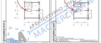
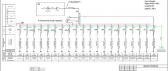
Drawing up a diagram
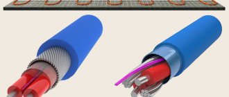
Modern power supply systems involve the use of a three-wire cable, where one wire is a phase, and the rest are ground and zero. Given the growing power of devices, it is also necessary to divide them into groups, which allows to increase the service life of the wiring. Guided by these principles, we proceed to drawing up a diagram of the shield.
Advice! It is better to entrust the design of the panel and electrical wiring of the apartment to a professional so as not to miss important details. Otherwise, you will have to redo the repair.
It is mandatory to install a protection device on the input cable, which will protect the internal network from overvoltage. Then they install a voltage relay to control surges in the network, after which they proceed to the installation of groups and individual lines. It is worth noting that for powerful devices, in addition to switches, additional RCDs or differential circuit breakers are used. Such organization of the home electrical network is not only safe, but also convenient. If necessary, you can turn off the machine and turn off the washing machine. You can also turn off the RCD and de-energize all consumers included in the global group.
How to connect the phase and neutral wires
Connecting the phase conductor to the machine is mandatory. The neutral conductor does not always have to pass through the machine, but there are cases when it is recommended to use a two-pole automatic switch, and then both phase and neutral pass through it - each wire through its own section.
Simultaneous disconnection of phase and neutral is justified especially in situations where three-phase voltage is introduced into a house or non-residential building. In such situations, there is a greater risk that one of the phases may short circuit to zero. This is a short circuit mode to which the machine protecting this phase must respond. But in those fractions of a second while it is triggered, an overvoltage will occur in the other two phases. That is, instead of the required 220 V, there may be all 380 V - the voltage difference between the two phases with a conventional three-phase connection.
Not a single household appliance is designed for such voltage, and the more powerful it is, the more current it passes, and the greater the likelihood of it burning out due to overvoltage. Where the fuse of a low-power device immediately blows, powerful equipment will still “tolerate” a heavy load for some time, and during this time the switching power supply or transformer may fail. Therefore, it is preferable to protect equipment such as boilers, dishwashers and washing machines with two-pole circuit breakers that cut two circuits at once.
Keep in mind that phase imbalance is also harmful to the source that powers the building. A generator, a transformer booth, a substation - all this will deteriorate very soon. For such purposes, there are special three-phase circuit breakers, which, in the event of a large imbalance or failure in one of the phases, can immediately turn off all three phases simultaneously. For more critical circuits, it is recommended to connect a four-phase circuit breaker, which also de-energizes the neutral wire.
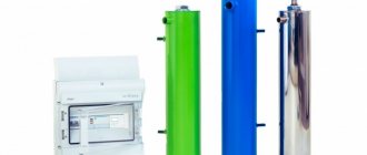
Electrical Panel Components
The distribution board consists of many devices. For reliable operation of the home electrical network and protection of household appliances, it is necessary to use circuit breakers, RCDs and differential circuit breakers, voltage control relays, buses and much more.
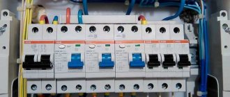
Circuit breakers
Devices for automatic protection of the line that is connected to them. They interrupt the power supply if the current in the line is significantly higher than the rated value. Protection against cable heating is also provided.
RCD and diffautomatic devices
The residual current device (RCD) switches off the load if leakage currents appear. First of all, people can suffer from them. The leak also negatively affects the wiring, causing the wires to heat up and catch fire.
Differential circuit breaker - protects against short circuits, overloads, and current leaks. It is often used instead of a combination of a pair of RCDs and a conventional machine. The main advantage is short circuit protection.
Voltage control relay
The device is used to measure the incoming voltage and maintain a given value. In case of sudden surges in the network, the device turns off the power supply. The electrical circuit is closed only after the indicator and time delay have been restored. The main purpose is to protect electrical appliances from power surges.
Grounding and grounding buses
Busbars for grounding and zero are used for ease of installation, as well as compliance of the shield with all the rules of GOST and PUE. The number of DIN rails depends on the number of machines and other modules, so it is necessary to draw up an installation diagram in advance.
Comb tire
It is used instead of cable jumpers, which were previously made by electricians themselves. The comb looks like a solid plate with protruding teeth and is designed to connect machines standing in the same row.
Other equipment
As additional equipment in the distribution panel, modular contactors, load switches, DIN rail sockets, timers and much more are used. Other devices increase the convenience of managing the power supply network.
A little about mechanics
Having dealt with the question of how to properly connect the machine, the question of how to install it remained unexamined. If you are planning a new shield, then most likely the first thing you will have to do is install a DIN rail there.
Each modern circuit breaker has a special clamp for mounting on this very rail. The feed-through contact, which is used for the grounding conductor, has the same fastening. By the way, the latch of such a grounding conductor is not made as a separate plastic element, but as a springy part of the housing. This is very convenient, as there is no risk of losing a small but very important detail.
If it is not possible to find a pass-through element, the grounding connection can also be made by twisting. However, to be sure, you can tin the wires with a soldering iron and put heat-shrink tubing on them as insulation. This is completely justified. Do not forget that phase and neutral conductors still “walk” along the shields. If you don't have heat shrink tubing, you can use insulating tape. This will be no less protection against any surprises.
By the way, it is strictly worth remembering that the connection and even grounding cannot be done in such a way as to twist copper and aluminum wires together. These two metals form a galvanic couple, which leads to their oxidation and disruption of conductivity between them. If it turns out that it is not possible to connect them through a pass-through element or a block with steel contacts, then you can tin each of the wires and carefully solder the connection.
How to calculate the number of places in an electrical panel?
All equipment for the switchboard is standardized and installed on a special DIN rail. The unit of measurement for space is considered to be a “module” with a width of 17.5 mm. All panels are sold depending on the amount of space: for 8, 12, 24, 36 modules.
Reference! To calculate the number of seats, it is necessary to take into account all devices, including RCDs, automatic machines, voltage relays, and differential automatic devices.
Circuit breakers have a standard width of 17.5 mm. The remaining devices have the following characteristics:
- two-pole circuit breaker - 2 modules and 35 mm;
- three-pole circuit breaker - 3 modules, 52.5 mm;
- single-phase RCD - 2 modules and 35 mm;
- three-phase RCD - 4 modules and 70 mm;
- diffautomatic - 2 modules and 35 mm;
- voltage relay - 3 modules, 52.5 mm;
- DIN rail socket - 3 modules, 52.5 mm;
- terminals for DIN rail - 1 module 17.5 mm.
Electrical panel assembly
When the panel diagram has been created and the electrical wires have been laid around the apartment, we proceed to assembling the panel. If desired, you can order a prepared shield, which all that remains is to install and connect the input cable.
Advice ! Indoor renovation is a messy process, so it is recommended to assemble the panel in another place, and then install the finished equipment in place.
Marking and installing DIN rails
First, markings are made of where the modules will be located and how long the slats are needed. During the fitting process, they also take into account the distance between the rows, if there are several of them, as well as the distance between the zero and ground buses. When the marking is ready, the slats are installed in the required places.
Reference! Most panels are standardized, so the placement of the slats is limited by the manufacturers.
Installation and switching of modular devices
At the stage of installation of modular devices, automatic machines and additional devices are installed on a DIN rail. They are also connected to each other. First of all, they install an input circuit breaker, then voltage relays, RCDs and differential circuit breakers, which are located in front of conventional switches.
Advice! Install the modules closer to the center, leaving space on the sides for neat cable management.
Organization of cable entry into the electrical panel
At the stage of cable entry, it is necessary to make holes in the shield. As a rule, all insertion points are provided by the manufacturer, so it is enough to squeeze out the plastic. On one side, a general network cable is installed, which is connected to the input circuit breaker, and on the other, internal network wires.
A little about mechanics
Having dealt with the question of how to properly connect the machine, the question of how to install it remained unexamined. If you are planning a new shield, then most likely the first thing you will have to do is install a DIN rail there.
Each modern circuit breaker has a special clamp for mounting on this very rail. The feed-through contact, which is used for the grounding conductor, has the same fastening. By the way, the latch of such a grounding conductor is not made as a separate plastic element, but as a springy part of the housing. This is very convenient, as there is no risk of losing a small but very important detail.
If it is not possible to find a pass-through element, the grounding connection can also be made by twisting. However, to be sure, you can tin the wires with a soldering iron and put heat-shrink tubing on them as insulation. This is completely justified. Do not forget that phase and neutral conductors still “walk” along the shields. If you don't have heat shrink tubing, you can use insulating tape. This will be no less protection against any surprises.
By the way, it is strictly worth remembering that the connection and even grounding cannot be done in such a way as to twist copper and aluminum wires together. These two metals form a galvanic couple, which leads to their oxidation and disruption of conductivity between them. If it turns out that it is not possible to connect them through a pass-through element or a block with steel contacts, then you can tin each of the wires and carefully solder the connection.
Basic installation mistakes
- A flexible multi-core cable without sleeves at the ends is a weak point in electricity. Over time, the quality of the contact weakens, the connection begins to heat up and cause problems.
- The cable insulation gets into the terminal, and at times of high loads it heats up and melts.
- Wires of different cross-sections per machine - this inevitably leads to poor contact, overheating of the wire and even a fire.
- Soldering the ends is an old and not reliable enough way to connect wires. Only suitable ferrules are used for connection.
Be sure to crimp stranded wire or use rigid solid cable.
Differential machines
In practice, instead of residual current devices, differential circuit breakers are often used.
These are devices that combine RCD and AV in one housing. It makes sense to use automatic devices if this device will protect a separate line or an individual consumer. If you protect several lines with a difautomatic device, then each will need to additionally install its own AB (unless, of course, the selectivity of the system is important to you, and you do not want to violate it).