Here you will learn:
- Types and purpose of check valve for pumping station
- Check valves for pumping stations: design types
- Where to install the check valve correctly
- Materials, markings, sizes
- Check valve installation rules
- Installation errors
- Possible malfunctions and methods for eliminating them
- Review of popular models
A check valve for a pumping station is an essential element of a water supply system. Thanks to this element, after turning off the pumping mechanism, water does not flow back to the source - thanks to the check valve, the pipeline always remains filled.
Types and purpose of check valve for pumping station
The dimensions of the check valve are small, but without this little detail it will be impossible to maintain the pressure in the water supply system. It belongs to the category of pipeline fittings whose main task is to prevent a reverse change in the flow of water in the pipes of the water supply system.
Household pumping equipment is not designed for its movement in an abnormal direction.
A check valve is used to allow water flow to flow in only one direction, completely blocking its path back (+)
There are models of pumping stations on the market, the manufacturers of which include a check valve. Such options are supplied with a suction hose with a built-in check valve. But in most cases, you have to purchase this fittings yourself.
Such valves are installed both on the suction line and at the entrance to the internal water supply system immediately after the pump with a hydraulic accumulator or in front of the pumping station.
Depending on the installation location in the water supply system diagram, check valves are divided into:
- Bottom. They prevent the reverse movement of water raised from the source when the pumping equipment is turned off. They create conditions for operating the unit without constant filling with water before starting it and the suction line.
- Pipeline. These include axial and valve varieties. Prevents a drop in the operating pressure in the system.
If there is no check valve at the end of the suction pipe of the pumping station, then when the pump stops, water will begin to flow back under the influence of gravity. As a result, air pockets will form in the line, and under “dry running” conditions, the seals will begin to collapse. As a result, water will penetrate into the electric pump and cause it to burn out.
Not only the starting point of the suction line can be equipped with a check valve. To ensure pressure support, it is installed on the pipeline in front of the pumping station or in front of the hydraulic tank when it is located separately
Most modern pumps are protected against such processes. But water for starting will have to be poured into them after each stop of the unit.
In some pump models, it is possible that the impeller spins up completely, which can lead to its failure. Installation of this fittings on the liquid intake line from the source is mandatory, otherwise no electronic protection will help the water pumping unit.
When connecting several pumping stations into a single unit, check valves protect the switched off unit from the pressure of operating devices
With a pipeline check valve the situation is somewhat different. Here it no longer protects the pump, but the water distribution system inside the house. By locking the water in the pipes, preventing it from returning back to the accumulator, the check valve helps maintain the required operating pressure in the system. Without it, water will rush back into the storage tank, causing it to work abnormally.
Check valves increase the efficiency and reliability of the pumping station, while protecting the pump, plumbing and water system from water hammer. Overall, it is an indispensable device. But the water has to expend effort to open the valve, which reduces the pressure of the flow after its passage by 0.1–0.3 atm.
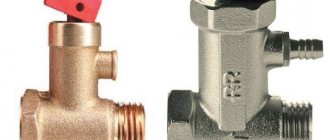
Bottom check valve
Bottom types of check valves are installed at the inlet of the water pumping line. They are used to equip surface pumping systems to protect against pressure drop.
The purpose of the bottom check valve is to retain water in the system and maintain the operating pressure level (+)
Based on their design specifics, bottom check valves are divided into:
- Spring. Their working locking mechanism consists of a spring and a disk, which, when the spring contracts under water pressure, moves along the body of the device and allows flow to pass.
- Casement. The main organ consists of one or two transverse valves that open under the pressure of pumped water and return to their place when it stops.
Based on the method of attachment to the end of the suction hose or pipe, bottom valves are divided into coupling and flange valves. In tandem with household pumping units, the coupling type is most often used.
Under water pressure, the spring of the device is compressed, and the locking disc attached to it opens the path for flow in only one direction
Coupled connections of check valves are easier to install, but require periodic condition monitoring, especially when working with a vibration pump
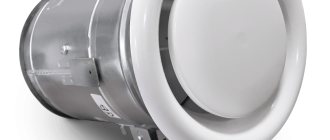
A flap check valve is the easiest to operate, repairable version of the device, the flap of which opens only in one direction under the pressure of pumped water (+)
It is recommended to install a strainer in front of the bottom check valve. He must prevent the penetration of biological contaminants and solid particles that have an abrasive effect into the pumping system.
The device must be installed in the direction indicated by the arrow on the housing. The distance from the bottom of the water intake shaft to the check valve must be at least 0.5 - 1.0 m, depending on the class of the unit and the manufacturer’s recommendations. Between the water surface in a well or borehole and the valve there must be a water thickness of at least 0.3 m.
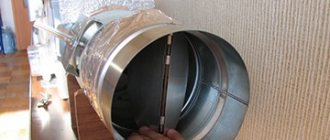
Pumping systems with a submersible pump are equipped with a check valve without a filter, because they are equipped with built-in cleaning devices to protect the functional “filling” from friction. The check valve in this case is installed in front of the supply pipe immediately after the pumping unit. Used to prevent pressure drop in the network.
The check valve in a pumping system with a submersible pump is installed immediately after the unit at the inlet of the suction pipe
Areas of application for a homemade product
This homemade check valve can be used in different cases:
Pump connection diagram.
- The water heating system is based on convection (warm water goes up and the return circuit comes from the bottom of the boiler). But often it is simply not possible to lay the circuit from below, then it is carried out from above, using a check valve;
- When installing solar collectors, it is necessary to take into account the small temperature difference between the water entering and exiting the device. In addition, the height difference of the pipes in the storage tank (tank) is small. To eliminate these shortcomings, a check valve is installed on the inlet pipe of the sun warmer;
- In order for the suction pump to function normally, it must be filled with water. To prevent water from draining when the pump is turned off, a check valve is installed at the suction end of the hose;
- many have encountered the problem of damage to the elements of electric heaters (TEHs) when there is a small amount of water in the tank. To solve this problem, install a check valve; it itself prevents the tank from draining when the water supply is stopped. Thus, the water heater elements are always filled with liquid and do not burn out;
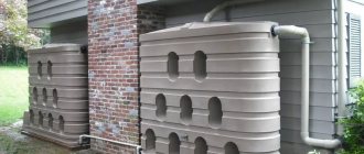
- If you do not have a central water supply at your dacha and you have to store water in different containers (for example, in 200 liter barrels), then in order to save space in your dacha, it is advisable to install water containers vertically. To properly fill barrels with water and save it, a homemade product is mounted on each existing container.
Check valves for pumping stations: design types
You can find a large number of similar devices on sale, which differ in design, material, size, and each has its own installation characteristics:
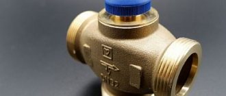
- A water check valve for a pump can most often be found with a lift-type locking element. The device is equipped with a shutter that rises up or down, preventing the movement of water. When water enters, the valve rises and lets it through, and when the pressure drops, the valve lowers and does not allow the liquid to return. The mechanism moves thanks to a special spring.
Valve operating principle
- Return parts for ball type pump. This type of device has a ball-shaped valve that blocks the path of liquid. When the water pressure drops, the spring lifts the ball and the system lets water through, and after the pressure drops, the element closes.
Ball product device
- Disk element. It has a disc-shaped shutter that moves along its axis using a spring.
Disk element design
- Double-leaf devices. Their shutter has two doors that fold when there is water pressure, and when there is no pressure, they close; all this is driven by a spring.
Disc and double-leaf devices
In everyday life, a part with a lifting type of mechanism is most often used. It can be repaired by replacing the spring.
Installation diagram for the station
Device
The design of any type of check valve includes a collapsible cylindrical body consisting of:
- reception areas (connections to the pipeline);
- limiter (one or two doors, ball, etc.);
- mechanism for fixing the limiter;
- outlet zones (fastenings with pipeline).
For the manufacture of body parts the following is used:
- brass;
- bronze;
- titanium;
- cast iron;
- steel (including alloy and stainless steel);
- non-metallic materials;
- high temperature ferritic steel.
The necessary tightness of the locking element on the seat is ensured by sealing surfaces, for the manufacture of which the following is used:
- durable rubber;
- plastic;
- corrosion-resistant steel, deposited in a thin layer.
Where to install the check valve correctly
Installation of such a design element of a water supply system is most often required directly at the point of water intake, that is, at the end of the pipe. This arrangement of this unit is applicable both for a pipe in a well and in a well when installing a surface suction pump.
A valve corresponding to the diameter of the pipe is installed using an adapter on the very bottom of the pipe, and thus prevents the outflow of water from the water supply.
A special feature of this option is the need to install, in addition to the valve, a mesh filter on it to prevent small stones and other debris from entering the chamber of the device. Such foreign objects may block the closing mechanism and thus render the valve inoperable.
For submersible centrifugal pumps that are constantly in water, the valve is installed immediately after the pump, but with this design it is recommended to install a flow filter with a sealed housing. This design will ensure a constant supply of water, since the column of water will be above the body of the device, and the space of the filter and pump chamber is already constantly under the water column.
Another similar option for installing the valve may be the option of installing it in conjunction with a diaphragm-type deep-well pump. Here, depending on the design of the pump, it can be installed either on the outlet pipe or as an insert into a pipeline or hose.
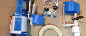
Tools
To make devices, you will need the following tools and equipment, which are probably available in every self-respecting home workshop:
- Desk or workbench.
- Vise or massive clamp.
- Hacksaw for metal.
- Drill or benchtop drill press.
- Pliers.
- Assembly knife.
- Set of files and needle files.
- Sandpaper of different grits.
- Jigsaw (electric).
Different materials and components are required for different designs and will be listed in the appropriate section.
Materials, markings, sizes
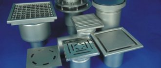
The check valve for water is made of stainless steel, brass, larger sizes are made of cast iron. For household networks, brass is usually used - it is not too expensive and durable.
Stainless steel is, of course, better, but it is usually not the body that fails, but the locking element. This is where you should approach your choice carefully.
For plastic plumbing systems, check valves are made from the same material. They come in polypropylene and plastic (for HDPE and LDPE). The latter can be welded/glued or threaded. You can, of course, solder adapters to brass, install a brass valve, then again an adapter from brass to PPR or plastic. But such a unit is more expensive. And the more connection points, the lower the reliability of the system.
For plastic and polypropylene systems there are check valves made of the same material
The material of the locking element is brass, stainless steel or plastic. Here, by the way, it’s hard to say which is better. Steel and brass are more durable, but if a grain of sand gets between the edge of the disk and the body, the valve jams and it is not always possible to return it to functionality. Plastic wears out faster, but it doesn’t jam. In this regard, it is more reliable. It’s not for nothing that some manufacturers of pumping stations install check valves with plastic discs. And as a rule, everything works for 5-8 years without failures. Then the check valve begins to “poison” and is replaced.
What is indicated in the labeling
A few words about the marking of the check valve. It states:
- Type
- Conditional pass
- Conditional pressure
- GOST according to which it is manufactured. For Russia, this is GOST 27477-87, but there are not only domestic products on the market.
Return valve for water: marking according to GOST
The conditional diameter is designated as DU or DN. When choosing this parameter, you need to focus on other fittings or pipeline diameter. They must match. For example, you will install a check water valve after a submersible pump, and a filter next to it. All three components must have the same nominal diameter. For example, all should have DN 32 or DN 32 written on them.
A few words about conditional pressure. This is the pressure in the system at which the shut-off valves remain operational. You should definitely take it no less than your working pressure. In the case of apartments - no less testing. According to the standard, it exceeds the working one by 50%, and in real conditions it can be much higher. You can find out the pressure for your home from the management company or plumbers.
What else to pay attention to
Each product must come with a passport or description. It indicates the temperature of the working environment. Not all valves can work with hot water or in a heating system. In addition, it is indicated in what position they can work. Some should only stand horizontally, others only vertically. There are also universal ones, for example, disk ones. That's why they are popular.
Opening pressure characterizes the “sensitivity” of the valve. For private networks it rarely matters. Only on supply lines close to the critical length.
Also pay attention to the connecting thread - it can be internal or external. Choose based on ease of installation. Don't forget about the arrow that indicates the direction of water movement.
Dimensions of check valves for water
The size of a check valve for water is calculated according to the nominal diameter and they are produced for all - even the smallest or largest pipeline diameters. The smallest is DN 10 (10 mm nominal bore), the largest is DN 400. They are the same sizes as all other shut-off valves: taps, valves, drains, etc. Conditional pressure can also be referred to as “dimensions”. The lowest is 0.25 MPa, the highest is 250 MPa.
Each company produces check valves for water in several sizes.
This does not mean that any of the valves will be in any variant. The most popular sizes are up to DN 40. Next come the main ones, and they are usually purchased by enterprises. You won't find them in retail stores.
And also, please note that for different companies, with the same nominal diameter, the external dimensions of the device may differ. The length is understandable. Here the chamber in which the locking plate is located may be larger or smaller. The diameters of the chambers also differ. But the difference in the area of the connecting thread can only be due to the thickness of the walls. For private houses this is not so scary. Here the maximum working pressure is 4-6 Atm. But for high-rise buildings it can be critical.
How to check
The easiest way to test a check valve is to blow into it in the direction that is blocking it. No air should pass through. At all. No way. Also try pressing on the plate. The rod should move smoothly. No clicks, friction, distortions.
How to test a check valve: blow into it and check for smoothness
Also inspect the seat and disc. Especially in the place where they are adjacent to each other. Everything should be even/smooth. The tightness of this type of fitting depends on how accurately everything fits. In more expensive models, a rubber/polymer/plastic sealing ring is installed on the plate. Needless to say, it should lie flat, without waves, and there should be no scratches or burrs.
Main settings
The check valve is characterized by quite a large number of different characteristics. The main ones can be called:
- Nominal diameter.
- Nominal pressure.
- Test pressure.
- Operating pressure.
- The pressure that occurs when the locking element opens.
- Bandwidth.
- Type of material used in manufacturing.
Some of the above parameters may be indicated by the manufacturer on the mechanism body. These must be taken into account when choosing the most suitable valve.
Check valve installation rules
There are two options for installing a check valve on a water supply system if it involves a pumping station:
- in front of the pumping station;
- immediately after the ratchet on the suction pipe.
The second option is considered the most optimal, because installing a check valve in front of the station can lead to a limitation in the volume of water required to be discharged into the suction pipe and subsequently captured by the pump when it is turned on.
In this case, along with the working medium, the pump can capture a portion of air. This leads to noise in the pipeline and the expulsion of the air plug when the water tap is opened.
Nominal pressure
One of the most important parameters is the nominal pressure. It is designated PN. The features of this indicator include the following points:
- The nominal pressure is related to the maximum pressure of water at a temperature of 20 degrees Celsius.
- With this indicator, long-term operation of the check valve is allowed.
The device is classified in accordance with GOST. It is worth considering that the high nominal pressure provides a wide range of applications for the device. This indicator is indicated by the manufacturer and must be taken into account when choosing the most suitable design option.
Installation errors
Common mistakes when installing a non-return valve:
- the direction of flow is not taken into account;
- connections are poorly sealed, which can lead to leaks when the valve is closed;
- the cross-section of the device is too large, so it knocks during operation;
- the valve is placed too close to the pump, which causes rattling;
- a lot of plumbing flax was used when winding the threads - the coupling may crack.
Sometimes they forget to remove the through hole plug or the shutter lock.
Possibility of making it yourself
There is no deep financial sense in making valves yourself; purchasing components will cost almost more than a ready-made industrial valve. Or the home workshop should have high-precision drilling, turning and milling machines for self-manufacturing of device parts.
Most often, home craftsmen make valves with their own hands to test their strength in design and assembly. They also make custom valves for home process units for making beverages or aquarium filtration and aeration systems. Next, the design and manufacturing technology of the valves will be considered:
- Ball for water.
- Gravity ball for water.
- Disc-shaped.
- Petal for ventilation.
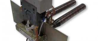
Figure 3. Reed air valve design
The designs chosen are simple, the technology does not require the use of expensive equipment. Making a simple check valve in a home workshop is quite possible. It is enough to have intermediate level locksmith skills.
Possible malfunctions and methods for eliminating them
Despite the high reliability of such devices, they, like any technical element, have operating features and can also break down and fail. Most often the check valve stops working:
- If debris and stones get into the housing;
- If the spring is damaged;
- When the surface of rubber or plastic seals wears out;
- Gradual aging and loss of elasticity of plastic and rubber;
- Exposure to water and chemicals dissolved in it.
Traditionally, if the valve operates unsatisfactorily, it is simply replaced, since the cost of replacing individual parts and assemblies far exceeds the price of a new one. But it is quite possible to extend the service life of such a device; to do this, it is enough to install a regular, simplest mesh filter at the inlet. Such a simple device is quite enough to almost double the service life of the valve.
Principle of operation
The operating principle of this type of locking device is quite simple and is as follows:
- water entering the device body under pressure affects the shutter and presses the spring, which holds it in the “closed” position;
- as long as the flow pressure level is high enough, the spring is in a compressed state and holds the locking element in the “open” position and water can flow freely through the device body in the required direction;
- when the pressure decreases or the direction of water movement changes, the spring mechanism of the valve returns the valve to the “closed” position.
By working in this way, the check valve prevents unwanted movement of fluid in the opposite direction.
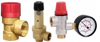
Review of popular models
Determining where to install the check valve is not the main thing you need to know about this element of the water supply system.
The modern market is represented by domestic and foreign representatives. V107, 19h21br, 16h42r – articles of the best modifications. These products are characterized by a long service life, reliability, unpretentiousness, and maintainability. But most importantly, installation work can be done with your own hands without the use of specialized tools and without spending money on the work of a construction team.
Test pressure
To determine the main characteristics of the check valve, a test pressure indicator was also introduced. In technical documentation this indicator is designated as Rpr. The test pressure is characterized as follows:
- Water is supplied at temperatures ranging from 5 to 70 degrees Celsius.
- At this pressure, a hydraulic test is carried out. It allows you to determine strength and density.
All check valves must be tested. This is due to the fact that such fittings are critical elements of any pipeline.