Why do you need vein coloring?
Color coding of the wires allows you to quickly figure out what each wire is responsible for.
Novice craftsmen who are just learning the basics of electrical engineering cannot immediately determine whether the white wire is a plus or a minus. Coloring is important in identifying cores and is called marking. Color marking of conductors is a necessity, allowing the master to quickly figure out what each core is responsible for. With its help you can understand what color the neutral wire is and where the phase is located. It also makes electronic circuits easier to read. It is especially important to observe color markings when connecting to meters, machines, and devices. Without painting, it is difficult to figure out which device may have failed and which circuit it is connected to.
Manufacturers paint cables in certain colors established by the rules of electrical installations PUE. They strictly regulate which markings should be used for a particular core. In addition, it is important to understand that the positive and negative contacts in the DC circuit have their own colors. What color the positive wire is is also determined by the rules.
In the case of an unmarked cable of the same color, a label with information can be placed on the ends of the product (for example, on a heat-shrinkable tube).
We are looking for a phase
You already know what color the wires are: phase, neutral, ground. Let's consider the main question - how to find the phase. If you are going to connect an outlet, then, in fact, you do not care about this issue - there is no difference to which contact you supply phase or zero to. But with a switch the situation is different.
Attention:
The phase in the switch always opens, and zero goes to the light bulb. This is necessary so that you do not get an electric shock during repair or replacement of the lamp. The phase must be connected to the bottom contact of the cartridge, zero - to the side.
If there are two wires of the same color in the wiring, then the easiest way to find the phase is with an indicator - when you touch the bare wire, it starts to glow. Before touching the wire, turn off the power, strip the insulation on the wire (1 cm is enough), separate the wires in different directions to prevent a short circuit. Then turn on the power and touch the indicator to the contact. The thumb should be placed on the top of the screwdriver, where the contact pad is located. After this, the LED on the indicator should light up. This will allow you to find the phase, but the device will not help you figure out between zero and ground. To find out what color the ground wire is in a three-wire wire, you will need to use the methods above.
You can find the phase using the indicator
Features of core colors
To avoid errors, the PUE requirements describe the colors of all main electrical wires. If the commissioning work was carried out by an experienced electrician who follows the rules of the Electrical Installation Code and the relevant GOSTs, during independent repairs you will not need either an indicator screwdriver or other devices that determine the purpose of a particular core.
Color marking in electrical equipment according to GOST
Three-wire DC system
In DC systems, a three-wire system is also used, but the purpose of the wires is different. The division is made into positive, negative and protective. According to GOST, the following color markings are used in such networks:
- Plus - brown;
- Minus - gray;
- Zero - blue.
Since it is irrational to produce separate wires for DC systems, the specified color gradation is used mainly for painting conductive busbars.
Grounding
The yellow-green wire is grounding. In circuit diagrams, grounding conductors are marked with the letters PE. In some older houses there are PEN wires in which the grounding is combined with the neutral conductor. If the cable was pulled according to the rules, wires with blue insulation were chosen, and only the ends and places of twists were yellow-green (thermal tubes were put on them). The thickness of the “zero” and grounding may be different. Often the thickness of these two conductors is less than the thickness of the phase conductor; this occurs when connecting portable devices.
When it comes to laying electrical wiring in multi-storey buildings and industrial premises, the norms of PUE and GOST 18714-81 come into force, requiring the mandatory installation of protective grounding. Grounding must have minimal resistance to compensate for the consequences of faults on the line and prevent harm to human health. That is, compliance with the standards for color marking of PUE wires is of paramount importance.
"Phase"
The color of the phase is what is of paramount importance for an electrician: handling conductive conductors requires care and knowledge. The slightest touch of the phase can lead to injury. There are many colors for phase wires marked in the form of the letter L in electrical wiring; the ban only applies to the use of blue, yellow and green colors. If the cable is three-phase, the serial number of the core is added to the letter L.
When a single-phase circuit is separated from a three-phase one, electricians use cables with strictly the same colors, monitoring the color of the phase and zero in the wire. Before starting work, they determine for themselves how the different wires will be connected, and then follow the chosen color. Sometimes thermal casings are fused onto them or several turns of colored appropriate electrical tape are wound.
According to GOST:
- black phase wires are used in power circuits operating with direct and alternating current;
- red color - used in control circuits designed for alternating current;
- with orange color - found in interlock control circuits powered from external sources.
What GOST and PUE say about color marking
The main document that you should rely on when producing or purchasing cables is GOST 31947-2012. Before its appearance, there was no uniformity and order in the field of color designation of electrical wiring.
Until now, in old houses you can find wires in the same sheath, the color of which cannot determine what is connected - “phase”, “zero” or “ground”.
Now it has become much easier to identify veins. Even without using a tester, you can determine which contact a particular core should be connected to - by the color of the polymer insulation. The above-mentioned GOST document states that the insulation of cable products should differ in color. A certain shade should cover the wire with a continuous layer - from beginning to end. It is impossible for one wire at the beginning of the bay to be blue and the end to be white; Intermittent painting is also prohibited.
The only vein that can have a two-color shell is the “ground”. Officially, it is assigned the green/yellow combination; these two shades cannot be used separately. The regulatory documents also contain recommendations for the use of various circuits for 3-core, 4-core and 5-core cables.
For example, when producing 3-core cables, the following combinations are welcome:
- brown – blue – green/yellow;
- brown – gray – black.
If the cable consists of 4 cores, then two standard color options are also recommended:
- brown – gray – black – green/yellow;
- brown – gray – black – blue.
The diagrams for a 5-core wire look like this:
- brown – gray – black – green/yellow – blue;
- brown – gray – 2 black – blue.
The blue color indicates the “zero” core.
It is not recommended to use only two colors - red and white.
There are special requirements for the distribution of colors of the grounding conductor: on any randomly selected piece of wire 1.5 cm long, one color must cover 30-70% of the insulation, the second color must cover the remaining area. The color must be applied firmly and be clearly visible.
Color designation
Factory markings include colored shells, alphabetic and digital coding. All insignia and color capsules are applied at the manufacturer.
Other types of designations:
- Color coding is used for wire terminations ; colored stickers and labels are placed. These designations are used by electricians when connecting cables to points of consumption.
- Electronic markers mark engineering and communication routes (power, pipelines, telecommunications).
The color of the sheath, specified in the factory, is designed to determine the properties of single-core or stranded wire, the scope of its use in industry, everyday life, and other performance characteristics. This information allows you to intelligently limit use. The marking is applied to the container or to the outer shell.
Phase
The preferred colors for live cables are brown, black and gray . In a single-phase network, such wires are brown in color. If a single-phase line is obtained as a branch from a working three-phase line, the color of the wire matches the color of the original cable of this circuit.
Features of European markings:
- standardized products are designated har (harmonized);
- digital combinations 07, 05, 03 show the actual voltage 450/750, 300/500, 300/300, respectively;
- the letters r or v indicate the type of insulation (rubber braids or PVC);
- elements U, R, K, F indicate the type of conductor (solid, stranded, soft for general wiring, soft, respectively).
Zero
The middle and neutral wires are made with blue braiding . This color cannot be used for conductors other than linear grounded ones.
If non-insulated conductors without a color designation are taken for the neutral line, they are painted in one of the following options:
- paint with blue stripes 20 - 100 mm wide in each connection;
- in accessible areas;
- along the entire length of the wire.
If the neutral cable is combined with protective grounding, it is painted yellow-green, with blue markings (stripes) along its entire length and ends.
Earth
Safety conductors are identified by a green-yellow combination . This combination is only acceptable for a grounding cable.
Coloring rules:
- The combination of yellow and green colors should be of such intensity that for every 1.5 cm of cable length, one of these colors covers the sheath of no less than 30% and no more than 70% of the total area.
- When using cores to protect a different color, they are coated with yellow and green compounds in each block, compartment and in a visible place.
- If you use adhesive tape for marking, it should be of two colors (yellow-green).
If the protective wire can be recognized by its shape and position, it is allowed not to color the wire along its length. It is recommended to mark visible areas and ends with the letters PE or two-color yellow-green stripes. The neutral working and protective cables must not be combined after being inserted into the building.
Core marking for electrical installation solutions
It is not for nothing that at the beginning of the article the idea was voiced that the color designation of conductors greatly simplifies the installation process. If you independently do electrical wiring in an apartment or private house, select wires according to the standards, when connecting electrical devices, installing automatic protection, distributing wires in junction boxes, you do not need to double-check where the phase, neutral, and ground are - the color of the insulation will tell you about this.
A few examples of electrical installations where marking is important:
- Depending on which electrical installations are connected and where the wires are sent next, the wires are connected in junction boxes
- For each core in the socket body there is a special contact. Typically the contacts, screw or clamp, are also marked
- The supply conductor is usually connected to the upper, fixed contacts, the ground - to the ground bus
- The simplest scheme: the neutral conductor is sent directly to the lamps, and the phase conductor is sent to the switch, from where it is also redirected to the lamps
There are cables with a large number of cores, the painting of which is not practical. An example is SIP, which uses a different method for identifying conductors. One of them is marked with a small groove along its entire length. The relief core usually performs the function of a neutral conductor, the rest play the role of linear ones.
To distinguish the cores, they are marked with tape, heat shrink, and letter designations, which are applied with multi-colored markers. And in the process of electrical installation work, a ringing is required - additional identification.
Electrical safety
The human eye does not see the electric field, and therefore is not able to detect live wires. Touching them is extremely dangerous and can be fatal. To protect people and reduce risks to the system, standards were adopted (GOST R 50462-92).
Oil-impregnated paper and plastic insulation are the most common in Russia. The first is used in an aggressive environment because of its ability to regenerate, that is, restore its previous properties. Today, PVC insulation is gaining great popularity.
Checking the correct connection
Unfortunately, not all electricians strictly follow the standards and make mistakes in choosing a conductor when making connections. Therefore, when hanging a chandelier, installing a socket or other electrical installation device, it is better to additionally check whether the insulation of each core corresponds to its purpose.
Mandatory checking of the neutral or phase is dictated by safety standards and the instinct of self-preservation: if you accidentally mix up the contacts during installation, you can get an unpleasant injury - an electrical burn. For identification, installers use two methods: the first is checking with an indicator screwdriver, the second is using a tester or multimeter. The phase is usually determined with a screwdriver, and neutral and zero are determined with measuring instruments.
How to use the indicator?
Even such simple devices as indicator screwdrivers are different. Some of them are equipped with a small button, others are triggered automatically when a metal rod and a current-carrying conductor or contact are connected.
But all models without exception have a built-in LED that lights up under voltage.
The indicator screwdriver is preferred by amateurs who do not have special qualifications. Professional electricians value accuracy, so they always have a tester with them. A screwdriver is a convenient tool for identifying the phase conductor. To find out whether the wire is working, use the metal blade of a screwdriver to gently touch the exposed wire.
If the LED lights up, the wire is energized. The absence of a signal indicates that it is ground or zero.
When using the indicator, you must adhere to the safety rules. Even if the screwdriver handle is insulated, it is recommended to wear protective gloves (with a rubberized inner layer), as when working with electricians in general. The verification procedure is performed with one hand, therefore, the other is free. It is better to also use it - for example, to fix wires. But it is strictly forbidden to touch the exposed parts of conductors or metal objects located nearby (pipes, fittings) with your second hand.
Rules for using the tester
An electrician's kit always includes a tester or multimeter. He has to work with the connection of conductors in electrical installations indoors and when assembling an electrical panel. If the wiring was installed a long time ago, marking the wires by color can be neglected.
Even if the insulation colors seem to be consistent, it is not a fact that they are connected according to all the rules.
Using the tester, you can find out not only the likelihood of connecting conductors to the electrical network, but also some parameters: current, resistance, voltage. With a multimeter you can test diodes, check transistors, and determine inductance. Before taking measurements, you should study the instructions that accompany all measuring instruments.
The procedure is approximately as follows:
- we set a value that is obviously higher than the expected voltage, for example, 260 V;
- connect the probes to the required sockets;
- we touch two conductors with probes - presumably phase and neutral;
- repeat the procedure with another pair of conductors.
The combination of phase-zero cores should produce a result close to 220 V. It will always be higher than the phase-ground pair. There are both digital, modern instruments on sale, as well as outdated ones, with arrows and value scales. It is more convenient to use digital ones. Before installing electrical devices yourself, we recommend learning how to use either an indicator screwdriver or a multimeter - you should not rely only on the color of the wires.
How to check the correctness of marking and wiring
Wire colors in electrical engineering are designed to speed up the identification of conductors, but relying only on colors is dangerous - they could be connected incorrectly. Therefore, before starting work, you should make sure that you have correctly identified their affiliation.
Take a multimeter and/or an indicator screwdriver. It’s easy to work with a screwdriver: when you touch a phase, the LED built into the housing lights up. So it will be easy to identify phase conductors. If the cable is two-wire, there are no problems - the second conductor is zero. But if the wire is three-wire, you will need a multimeter or tester - with their help we will determine which of the remaining two is phase and which is zero.
Determining the phase wire using an indicator screwdriver
We set the switch on the device so that the selected jackal is more than 220 V. Then we take two probes, hold them by the plastic handles, carefully touch the metal rod of one probe to the found phase wire, the second to the supposed zero. The screen should display 220 V or the current voltage. In fact, it may be significantly lower - this is our reality.
If 220 V or a little more is displayed, this is zero, and the other wire is presumably “ground”. If the value is less, we continue checking. With one probe we again touch the phase, with the second - to the intended grounding. If the instrument readings are lower than during the first measurement, there is “ground” in front of you and it should be green. If the readings turn out to be higher, it means that somewhere there was a mistake with “zero” in front of you. In such a situation, there are two options: look for exactly where the wires were connected incorrectly (preferable) or simply move on, remembering or noting the existing position.
So, remember that when testing a phase-zero pair, the multimeter readings are always higher than when testing a phase-ground pair.
And, in conclusion, let me give you some advice: when laying wiring and connecting wires, always connect conductors of the same color, do not confuse them. This can lead to disastrous results - at best, equipment failure, but there may also be injuries and fires.
How to determine ground, zero and phase on wires if there are no markings
It is more difficult to determine in practice than in theory. Not all manufacturers comply with the standards. Therefore, when laying a two-phase 220 V network with grounding, you have to use a VVG cable with blue, brown and red colors. Combinations may be different, but without complying with regulatory requirements.
For your information. In old wiring from “Soviet times” there is no color marking. Identical white (gray) shells do not allow the purpose and correspondence of the lines to be known by simple visual inspection.
To avoid problems, it is recommended to carry out installation work using the same type of cable products. When color coding is not available, it should be created at the joints using insulating tape or heat shrink tubing. The latter option is preferable, as it is designed to maintain integrity for a long time.
Below are methods for determining phase and neutral wires with the advantages and disadvantages of each option. In any case, first clarify the network parameters. In old houses, for example, a two-wire connection scheme with a single working and grounding conductor is often used.
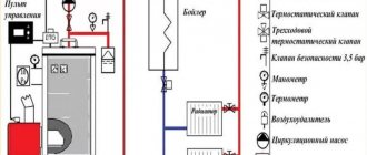
TN-S grounding diagram. The figure shows a modern network with separate grounding and working zero connections. It is possible to connect three- and single-phase loads.
Determining the phase using an indicator screwdriver
Touching the tip of such a device to the phase wire closes the current circuit. This is accompanied by the warning lamp or LED lighting up. A built-in resistor limits the current to a safe level.
Design of an indicator screwdriver.
Advantages of the indicator:
- minimum cost;
- compactness;
- reliability;
- durability;
- autonomy;
- good protection from adverse external influences.
The disadvantage is the limited measurement accuracy. Under certain conditions, false positives cannot be ruled out.
Determination of ground, zero and phase using a test lamp
To reproduce this technology, you need to prepare a simple design. An incandescent lamp designed for the appropriate mains voltage is screwed into a standard socket. Connect wires of sufficient length to perform work operations in a specific location. Next, connect one of the wires to the known zero line. Others sequentially check other cable cores. Lighting of the lamp indicates the presence of a phase.
Using a measuring device
When checking a 220 V household network, you do not need to know how to determine the polarity. The power supply is organized using alternating current, so set the multimeter switch to the appropriate position. Touching the phase-zero (phase-ground) wires with the probes is accompanied by an indication of the corresponding voltage (≈220 V). The potential difference between the neutral conductor and ground is minimal.
When checking an old two-wire circuit, one of the probes touches the reinforcement in a concrete slab, a radiator of a heating system, or another grounded element of a building structure. When switching to constant voltage, the multimeter will show where the plus and minus are. In the absence of reliable information about the electrical parameters in the circuit, they begin with the maximum measurement range with a sequential transition to smaller values with insufficient accuracy.
Such a “device” is useful for testing DC circuits in the absence of specialized measuring instruments. Bubbles near the negative wire are the release of hydrogen during the electrolysis reaction. The area near the plus will take on a greenish tint after a few minutes.
Using LED
You can create a control device with your own hands by analogy with an indicator screwdriver. Instead of a light bulb, install AL 307 or another LED with similar characteristics. A 100-120 kOhm resistor with a power of 1-2 W is added in series to the circuit.
How to determine the purpose of a wire - neutral or ground?
LN marking in electrical engineering is not always observed in old buildings, so the question arises of independently distinguishing between the neutral wire and the ground wire. When the circuit is closed, an electric current passes through the “zero”. The grounding wire has only a protective function, and in “normal” mode no current flows through it.
You can find out whether it is “zero” or “ground” like this:
- Use an ohmmeter, first turning off the voltage between the measurement points. The resistance on the ground wire will not exceed 4 ohms.
- Use a voltmeter and sequentially measure the voltage between the “phase” and other wires (the method is suitable for three-core cables). The ground wire will give the greatest value.
- If the colors of the “phase”, “zero” and “ground” wires are unknown, and you need to find out the voltage between the ground wire and some known grounded object (for example, a heating radiator), a voltmeter is also useful. True, when connecting the “earth” and a grounded object, it will not show anything. But a small voltage will be reflected in its indicator if you do the same with the “zero” wire.
In a two-core cable there will always be only a phase and neutral wire.
Wire Classification Options
The typical cable name contains letters and numbers. By decoding these symbols you can find out the main characteristics of products in this category:
- conductor (shell) materials;
- number of cores;
- cross-sectional area;
- Extra options.
Example of decoding (AVBbv-ng):
- A – the core is made of aluminum (copper is not marked);
- B – insulating shells are made of PVC;
- BB – protection against mechanical damage, made of steel tape without a damping gasket;
- ng – components that prevent combustion have been added to the polymer shell.
Ground wire color
By modern standards, the ground conductor is yellow-green. It usually looks like yellow insulation with one or two longitudinal bright green stripes. But there are also transverse yellow-green stripes in color. This color can be grounding.
In some cases, the cable may only have yellow or bright green conductors. In this case, the “earth” has exactly this color. It is displayed in the same colors on diagrams - most often bright green, but it can also be yellow. Signed on circuit diagrams or on ground equipment in Latin (English) letters PE. The contacts to which the “ground” wire must be connected are also marked.
Sometimes professionals call the grounding wire “neutral protective”, but do not be confused. This is an earthen one, and it is protective because it reduces the risk of electric shock.
What color is the neutral wire?
Zero or neutral is blue or light blue, sometimes blue with a white stripe. Other colors are not used in electrical engineering to indicate zero. It will be like this in any cable: three-core, five-core or with a large number of conductors.
What color is the neutral wire? Blue or light blue. “Zero” is usually drawn in blue on diagrams and signed with the Latin letter N. Experts call it a working zero, since, unlike grounding, it participates in the formation of the power supply circuit. When reading a diagram, it is often defined as "minus", while the phase is considered "plus".
Five-wire system
For a three-phase connection, five-core wires are used. Accordingly, three wires are allocated for phases, one for neutral or zero and one for protective, grounding. Color marking, as in any alternating current network, is similar, in accordance with GOST requirements.
In this case, the correct connection of the phase conductors will be an important point. As can be seen in the figure, the protective wire is made in a yellow-green braid, and the neutral wire is in blue. Allowed shades are used for the phases.
Using five-core wires, you can connect a 380 V network with correct wiring.
Color of wires plus (+) and minus (-) in DC networks
Is the red wire positive or negative? Such questions arise when working with DC electrical circuits.
Red
To remember which plus is red or black, they use the name of a well-known international organization - the Red Cross. This phrase suggests that red means plus.
Black
Black color indicates the negative conductor. These markings can be seen on typical household equipment:
- power supplies;
- audio, video equipment;
- other devices with electronic software control units.
Plus
The polarity of conductors must be observed when repairing standard electrical equipment of cars. In some situations, confusion with plus and minus is accompanied by a violation of the functional state.
Minus
The high power of connected consumers increases the responsibility for performing repair and adjustment work. In such situations, it is necessary to eliminate errors in determining polarity. Strong direct current is used to supply electricity:
- warehouse and municipal transport;
- lifting mechanisms;
- sensors and automation.
Wiring inside the house
Wiring inside the house is carried out only with single-phase lines and copper wires. In electrical circuits used for domestic purposes, the working zero should always be blue! According to the PUE, intra-house lines must be laid with a grounding conductor. In all three-core conductors made in accordance with GOST, suitable for interior work, the grounding wire is yellow-green.
If the three-core conductor is flexible PVA type, then the phase conductor is usually brown. For indoor wiring, it is better to use wires made of cast copper. If the conductors are marked with stripes, then a conductor with a stripe of any color except blue and yellow-green is phase.
If the cable does not have a yellow-green conductor, use a conductor with a green stripe as the ground wire. The ground wire may be marked in pure yellow. In cables whose cores are entirely painted, the white wire is the phase wire.
Connection to electric stove
A 220 V household electric stove is connected to a special outlet that can withstand high power. The colors of the conductors are red, green, blue, where red is the phase, green is the ground, blue is the neutral conductor.
There is a nuance: in foreign-made electric stoves and hobs designed for 220/380 V, the connection is made with a four-wire cable:
- blue – zero;
- yellow-green conductor – grounding;
- black conductor – phase A;
- brown conductor – phase B.
When connecting to a single phase network, it is allowed to combine the phase conductors on the electric stove under one contact clamp.
Neutral wire
The neutral conductor is the wire connected to the middle (null) point of the electrical system. In the standard connection diagram, this is a combined neutral working and neutral protective conductor in a three-phase circuit. The color of the neutral wire is all blue with yellow-green ends or all yellow-green with blue ends.
Wires are marked by color, letters and numbers. GOST until 2009 interpreted the possibilities of marking wires more broadly. Since 2009, the standards have been revised towards a more clear classification of colors and have eliminated notes that make it possible not to mark conductors.
The 2009 national standard clarified the terminology and expanded the alphanumeric classification. For electrical circuits until 2009, classic conductor colors were used: yellow, green, red.
In the classic version of three-phase circuits up to 1000 volts, conductors are marked in the following combinations:
- Phase A – L1, yellow – brown recommended.
- Black is recommended in phase B – L2, green.
- Phase C – L3, red – gray recommended.
- Neutral conductor – N blue.
- Combined working neutral with grounding conductor - PEN, blue with yellow-green tips - yellow-green with blue tips.
- Grounding conductor – PE, yellow-green.
This combination does not imply either the direction of rotation or phasing.
Letter designation of wires
Color markings can be supplemented by letters. Partially the symbols for the designation are standardized:
- L (from the word Line) - phase wire;
- N (from the word Neutral) - neutral wire;
- PE (from the combination Protective Earthing) - grounding;
- “+” - positive pole;
- “-” — negative pole;
- M is the midpoint in DC circuits with bipolar power supply.
To designate the protective grounding connection terminals, a special symbol is used, which is stamped on the terminal or on the device body in the form of a sticker. The grounding symbol is the same for most countries in the world, which reduces the likelihood of confusion.
In multiphase networks, the symbols are supplemented by the serial number of the phase:
- L1 - first phase;
- L2 - second phase;
- L3 - third phase.
There is marking according to old standards, when the phases are designated by the symbols A, B and C.
A deviation from the standards is the combined phase designation system:
- La - first phase;
- Lb - second phase;
- Lc - third phase.
In complex devices, additional symbols may be found that characterize the name or number of the circuit. It is important that the markings of the conductors match throughout the entire circuit where they are involved.
Letter designations are applied with indelible, clearly visible paint on the insulation near the ends of the cores, on sections of PVC insulation or heat-shrinkable tube. Connection terminals may have marks that indicate circuits and power polarities. Such signs are made by painting, stamping or etching, depending on the material used.
Letter marking
Standard PUE recommendations concern not only color, but also letter markings.
Main types of phase and zero designation:
- Grounding conductor - PE;
- Zero cable - N or 0 (zero);
- Live phase - L.
Multicore cables are designated in sequence from L to LN, for example, L1, L2, L3, etc. The markings of all phase wires are different, for example, purple, gray, brown, red.
Additional marking of wires
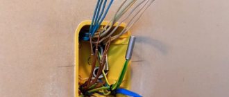
If the purchased cable has conductors of a color that does not comply with the standards, or the wiring has already been laid and is incorrectly marked, additional identification must be carried out.
Additional marking of wires.
During the electrical installation process, the ends of the wires are marked using heat-shrinkable tubing or colored insulating tape. Additionally, the letter designation of the cores can be applied to the wire or a tag attached to the wire:
- L – phase.
- N – neutral (working zero).
- PE – ground (protective grounding).
How to mark a wire with two cores
If all the wires in the cable have the same insulation, and the electrical appliance is already connected to the network, the craftsmen use indicator screwdrivers. The latter glow when the metal part touches the phase wire. To mark a two-core cable, in addition to such a screwdriver, you will need thermal casings or multi-colored electrical tape. Colors will be marked only at the joints - it is not necessary to wrap the core with colored tubes or electrical tape along its entire length.
Probe screwdriver-indicator
Phase wires can be marked with any colors except blue, yellow and green. If a two-core cable is connected to a single-phase network, it is customary to secretly mark the phase wire in red.
Security measures
When working with electric current, the following precautions must be taken:
- Use devices only for their intended purpose;
- Do not turn on equipment with damaged wires and plugs, do not use faulty sockets;
- Do not touch wires or outlets with wet hands or while standing on a wet floor. When working in a room with high humidity, you need to use rubber gloves and a mat;
- Do not bend wires and cables;
- Before starting work, it is worth disconnecting the entire network;
- If the equipment sparks or starts to catch fire when turned on, do not touch it. It is necessary to turn off the power through the panel;
- If you have any doubts or fears, it is better to contact a specialist or choose a safer option, for example, determining the polarity using a potato rather than connecting to a device.
Most often in batteries, the red wire indicates positive, the black wire indicates negative, and there are no problems when working with electricity. However, today many countries use their own color designations or abandon them altogether, leaving the wires uniformly white. In order not to create emergency situations, it is worth checking the polarity first.
Neutral line color N
Neutral conductor N is marked in blue. This is a wire that, like a phase wire, is necessary for the proper functioning of an electrical device. However, this is where the similarities between these wires end.
Useful: Wiring diagram for a double switch for 2 light bulbs in a chandelier
The N conductor is connected to the neutral point of the power transformer and is grounded, which means the ground voltage should be 0 V. As a result, touching the neutral conductor will not cause an electric shock (in theory). But you should always be careful when it comes to electricity. It is not known exactly how the electrician performed the installation and whether the network complies with the standards.
Marking of wires in a single-phase 220 V network
Considering this type of network, two variations can be distinguished. The first consists of two cores, the second - of three. As you can understand, the main difference between them is the presence or absence of a grounding conductor (PE).
Two-wire wiring is an outdated type and is becoming less common. This design is permitted by GOST and is suitable for premises with low safety requirements. The two-wire TN-C wiring used in older homes had a combined neutral and ground (PEN). Taking into account modern requirements, such a scheme is considered unsafe.
How and with what colors are the wires marked in two-wire single-phase wiring? Let's consider several options:
| (L) | (N) | If you use a solid wire with a brown and blue core, then the first should go to the phase, and the second to the neutral working conductor. This order should not be changed. The only exception is that black, red, gray, purple, pink, white, orange, and turquoise can be used to mark the phase conductor. To be on the safe side, it is recommended to mark the corresponding cores at both ends with tags labeled L (phase) and N (zero). | ||
| (L) | (PEN) | This circuit has a traditional brown conductor as a phase conductor (L). As in the previous case, the brown coating can be replaced with one of the acceptable colors. The three-color (yellow, green, blue) conductor (PEN) is used simultaneously as a zero working (N) and a zero protective (PE). Despite the combination of N and PE, in fact, the end user does not have grounding. | ||
Starting from the seventh edition of the PUE (electrical installation rules), electrical wiring in an apartment or house must be carried out with a three-wire cable with copper conductors ( three-wire circuit ).
Let's look at which conductors are included in a three-wire circuit and how they are marked:
| Phase L (from English Live - live) is a working wire under high voltage. | The main color of the core is brown (possibly a brown stripe on a white background) | ||||
| Acceptable core color: black, red, gray, purple, pink, white, orange, turquoise. | |||||
| Neutral (working zero) N (from English Neutral) is a voltage-free auxiliary conductor through which load current flows in operating condition. | The main color of the core is blue, light blue (possibly a blue stripe on a white background) | ||||
| Earth (protective zero) PE (from English Protective Earth - protective earth) is a separate unloaded conductor for grounding. Under normal conditions, no current flows through the protective zero. | The main color of the core is yellow and green stripes (possibly a green stripe on a yellow background). | ||||
The difference between earth and neutral
Electric current flows through the phase and neutral wires, so you should not touch them. Ground is used to redirect voltage when it reaches the body of an electrical device. Such protection used to be installed at the discretion of the user, but has now become mandatory almost everywhere, since the device will not even turn on without prior grounding.
If you ignore this criterion, the accumulated electricity will lead to a breakdown or the passage of current through a person. When it is impossible to understand the wiring by colors, the following methods are used:
- Measure the resistance; normally it does not exceed 4 ohms. First find out if there is resistance there, otherwise the multimeter will burn out.
- Determine the phase, and then use a voltmeter to measure the voltage that accumulates between the ground and the neutral. It is always higher for the first element.
- Measure the voltage between ground and any other safe device, such as a battery. In this case, the equipment will not detect voltage.
This algorithm only works on a three- or five-core cable; in all other cases, the ground is colored blue, and the phase is colored brown or green.
How to properly check using a multimeter or tester
To carry out the test, a scale is set on the device that exceeds the expected voltage in the network. For residential buildings, it is enough to set the switch to the 250 V position. After this, one probe touches the bare neutral wire (it should have a blue insulation color), and the second to the phase. If the assumptions turned out to be correct, then the indicator shows a figure close to 220 V. The ground wire is checked in this way, but the device shows lower numbers.
Very often, phase, neutral, and ground conductors are not designated by color. Then all pairs are checked and their purpose is determined by indicators.
Phase definition Source domamaster.net
Basic definitions
In AC electrical networks up to a thousand volts, the color marking of wires and cables is strictly regulated by state regulations, such as the “Rules for Electrical Installations” (PUE), and this is what the section of the seventh edition in Chapter 1, paragraphs 1.1.29 - 1.1.30 is responsible for. It states that “Identification of wire cores by colors or digital designations” must be used in accordance with GOST P 50462-92 (IEC 446-89). The marking has the following basic designations:
- PE – protective neutral conductor (ground) – bright yellow with a green stripe, or alternating green and yellow stripes;
On the diagrams: 1 ground, ground; 2 protective grounding; 3 and 4 connection to the body or chassis (ground).
- N – zero working conductor (neutral) – blue color;
- PEN - neutral and working, combined in one conductor - yellow-green in color with a blue stripe at the connection point;
- L – line (phase) – can be white, gray, brown, black or purple.
Important! It is recommended not to use or produce wires of green and yellow shades to avoid resemblance to the grounding conductor.
In 3-phase AC distribution boards, the busbars are painted:
- yellow – L1 (phase A);
- green – L2 (B);
- red – L3 (C);
- blue – block of neutral working conductor N;
- alternating longitudinal or transverse stripes of the same width of yellow-green color - PEN grounding bus.
Important! If the electrical panel housing also serves as a grounding contact, then the location where the wires are connected is indicated by a sign (ground) and is colored yellow-green.
The PUE allows you to designate the color of the main wires, phase and zero, not along the entire length of the bus, but only at the points of connection to the contacts; if the bus is invisible, you are allowed not to color it.
Important! When installing electrical equipment located in the same building, it is necessary to use color marking of wires and cables using the same color schemes.
We must not forget that the designation of wires by color should in no case reduce the degree of electrical safety and convenience when repairing or servicing electrical equipment.
Rules for observing the colors of electrical wiring during installation
A three-core or two-core wire is laid from the distribution box to the switch, depending on what type of switch is installed: a single-key or two-key switch. The phase is broken, not the neutral conductor. If there is a white conductor available, it will be the power supply. The main thing is to maintain consistency and consistency in coloring with other electricians, so that it doesn’t turn out like in Krylov’s fable: “The Swan, the Crayfish and the Pike.”
On sockets, the protective conductor (yellow-green) is most often clamped in the middle part of the device. We maintain polarity, zero worker is on the left, phase is on the right.
But there are surprises from manufacturers, for example, one conductor is yellow-green, while the other two may turn out to be black.
Perhaps the manufacturer decided, if there was a shortage of one color, to use what was available. Don't stop production! Failures and errors happen everywhere. If you come across exactly the same one, it’s up to you to decide where the phase is and where the zero is, you just need to run around with the control.
How to check the correct connection of wires
Very often, to connect additional sockets, lighting fixtures or household appliances, you need the ability to determine phase, neutral or grounding. This will prevent short circuits or shock hazards. Also, if there are errors in the connection, the device is guaranteed to fail.
Result of connection error Source argest-sv.ru
In new wiring, the colors of the wires must correspond to their purpose. In cases of old wiring, you should understand the purpose of each line and attach a tag or other mark to it.
Conductors can have several layers of protection Source promkabel.ua
What to do if there is no marking
Before purchasing a wire, you should pay attention to the presence of markings and their compliance. But there are cases when there is no marking or it does not meet the requirements. Then it is necessary to carry out manual marking using electrical tape, or use special cambrics - insulating material in the form of hollow tubes. All marks should be on the ends of the wire and where there are connections. To avoid such situations, it is worth purchasing wiring with a reserve so that it has the same markings throughout the house or apartment.
Heat-shrinkable casing decreases in diameter under the influence of high temperatures Source amperof.ru
How to detect phase
In order to find out what color the phase is, you need to use an indicator screwdriver. Multimeters or testers are used to determine the zero or ground line.
There are several types of indicator screwdrivers, but if there is voltage in the wire, a light signal appears. To detect the phase, you need to touch the bare conductor with the metal part of the instrument. Since the wires are live, you can only touch the insulation layer with bare hands. Exposed ends are very dangerous. Also, during the inspection, you should not touch objects that conduct electricity with your second hand, this is dangerous to your health.
During the check, do not forget about the safety rules Source prodecor-spb.ru