Designing ventilation for a residential, public or industrial building takes place in several stages. Air exchange is determined based on regulatory data, the equipment used and the individual wishes of the customer. The scope of the project depends on the type of building: a one-story residential building or apartment is calculated quickly, with a minimum number of formulas, but serious work is required for a production facility. The methodology for calculating ventilation is strictly regulated, and the initial data is specified in SNiP, GOST and SP.
Why is ventilation needed?
The task of ventilation is to provide the necessary air exchange in the room, to create optimal or acceptable conditions for a person’s long stay.
Research has found that people spend 80% of their time indoors. In one hour at rest, a person releases 100 kcal into the environment. Heat transfer occurs by convection, radiation and evaporation. If the air is not moving enough, the transfer of energy from the surface of the skin into space slows down. As a result, many body functions suffer and a number of diseases arise.
Model of a house with a ventilation system Source yandex.ru
Lack or insufficient ventilation, especially in rooms with high humidity, leads to stagnation. They are accompanied by an invasion of difficult-to-remove mold fungi, unpleasant odors and constant dampness. Moisture has an adverse effect on building structures, leading to rotting of wood and corrosion of metal elements.
With excess draft, the release of air masses into the atmosphere increases, which in winter leads to the loss of a large amount of heat. Home heating costs are rising.
The quality and purity of air is the main factor that determines the effectiveness of ventilation. Polluting fumes from building materials, furniture, dust and carbon dioxide must be removed from the premises in a timely manner.
There is the opposite situation, when the air in a house or apartment is much cleaner than outside. Exhaust gases on a busy highway, smoke or soot, and toxic pollution from industrial enterprises can poison the indoor atmosphere. For example, in the center of a large city, the content of carbon monoxide is 4-6 times, nitrogen dioxide is 3-40 times, and sulfur dioxide is 2-10 times higher than in rural areas.
Ventilation calculations are carried out to determine the type of air exchange system, its parameters, which will combine the energy efficiency of housing and a favorable microclimate in the premises.
Design errors
At the project creation stage, errors and shortcomings are often encountered. This may be excessive background noise, reverse or insufficient draft, blowing (upper floors of multi-storey residential buildings) and other problems. Some of them can be solved after installation is completed, using additional installations.
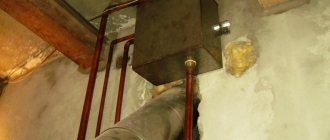
A striking example of low-skilled calculation is insufficient exhaust draft from a production facility without particularly harmful emissions. Let's say the ventilation duct ends in a round shaft, rising 2,000 - 2,500 mm above the roof. Raising it higher is not always possible or advisable, and in such cases the principle of flare emission is used. A tip with a smaller diameter of the working hole is installed in the upper part of the round ventilation shaft. An artificial narrowing of the cross-section is created, which affects the rate of gas release into the atmosphere - it increases many times over.
Sample Project
The method for calculating ventilation allows you to obtain a high-quality internal environment by correctly assessing the negative factors that worsen it. We employ professional designers of engineering systems of any complexity. We provide services in Moscow and neighboring regions. The company also successfully engages in remote collaboration. All communication methods are listed on the “Contacts” page, please contact us.
Microclimate parameters for calculation
Standards in accordance with GOST 30494-2011 determine the optimal and permissible air quality parameters in accordance with the purpose of the premises. They are classified by standards into the first and second categories. These are places where people relax, lying down or sitting, and engage in study and mental work.
Depending on the period of the year and the purpose of the room, the optimal and permissible temperature is 17-27°C, relative humidity 30-60% and air speed 0.15-0.30 m/s.
Gravity ventilation Source remontik.org
In residential premises, when calculating ventilation, the necessary air exchange is determined using specific standards, in industrial premises - according to the permissible concentration of pollutants. In this case, the amount of carbon dioxide in the air should not exceed 400-600 cm³/m³.
See also: Catalog of companies that specialize in interior redevelopment of houses.
Which air ducts to choose?
Round pipes with a smooth inner surface have low resistance; in rectangular shapes, turbulence at the corners slows down the flow. The rough surface of brick channels and corrugated pipes have maximum resistance to air movement. Therefore, the walls of the brick shaft are plastered, and the “corrugation” is used only for flexible turns and short sections.
The movement of air is hampered by the accumulating static electricity on the walls of plastic pipes. Therefore, galvanized steel pipes remain the best material for ventilation in a private house.
Ventilation ducts are insulated in cold areas (attic). The supercooled walls of the shaft slow down the draft and collect condensation. Therefore, in winter the canal can be completely covered with frost. A layer of insulation (50-70 mm) corrects the situation.
Condensation also settles on the pipes due to lack of draft. This is a signal to review the entire system. It is necessary to reduce the length of the air ducts, the number of turns and horizontal sections. In summer, it is advisable to increase the draft with fans. With constant air movement, moisture is not retained.
Types of ventilation systems according to the method of creating draft
The movement of air masses occurs as a result of pressure differences between layers of air. The greater the gradient, the stronger the driving force. To create it, a natural, forced or combined ventilation system is used, which uses supply, exhaust or recirculation (mixed) methods of air removal. Emergency and smoke ventilation are provided in industrial and public buildings.
Natural ventilation
Natural ventilation of rooms occurs according to physical laws - due to the difference in temperature and pressure between the external and internal air. Even during the times of the Roman Empire, engineers installed the likes of shafts in the houses of the nobility, which served for ventilation.
The natural ventilation complex includes external and internal openings, transoms, vents, wall and window valves, exhaust shafts, ventilation ducts, and deflectors.
Natural ventilation Source rumahku.com
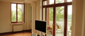
The quality of ventilation depends on the volume of passing air masses and the trajectory of their movement. The most favorable option is when the windows and doors are located at opposite ends of the room. In this case, when air circulates, it is completely replaced throughout the room.
Exhaust ducts are placed in rooms with the highest levels of pollution, unpleasant odors and humidity - kitchens, bathrooms. Supply air comes from other rooms and pushes exhaust air out into the street.
In order for the hood to work in the desired mode, its top must be 0.5-1 m above the roof of the house. This creates the necessary pressure difference to move air.
Natural ventilation is silent, does not consume electricity, and does not require large investments in the device. Air masses penetrating from outside do not acquire additional properties - they are not heated, not purified or moistened.
Air recirculation is limited to one apartment. There should be no suction from neighboring rooms.
Forced ventilation
Forced ventilation began to be used from the mid-19th century. At first, large fans were used in mines, in the holds of ships, and in drying shops. With the advent of electric motors, a revolution occurred in room ventilation. Adjustable devices have appeared not only for industrial, but also for domestic needs.
Forced ventilation Source stroy-podskazka.ru
Influx places
By natural draft, fresh air enters the house through slightly open windows, however, then most of the home heat evaporates. To avoid heat loss, air inlet valves (inlet valves) are used, which constantly allow a certain volume of air to pass through.
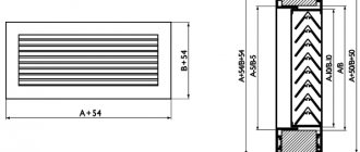
The pipe, limited by gratings, goes right through the wall. The position of the lid regulates the flow rate from 40 to 100 m3/hour. The installation is located far from the doors, often behind radiators, above 2 m above ground level. The base valves are manually adjusted.
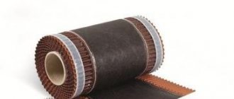
Rice.
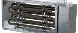
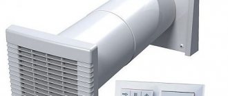
2 — Supply valve KIV Automatic ventilators (breathers) are adjusted by humidity and temperature sensors, which saves time and up to 5% of heating costs. Inside the case there is a built-in fan, which is set with parameters for a certain volume of air (power 3-7 W). The inflow rate is adjustable from 12 to 150 m3/hour.
Rice. 3 — Automatic ventilator (breather)
The installations create excess pressure in the rooms, which helps move stagnant air into channels with natural draft (even if the draft is weak). Ventilators are often equipped with filters for dust removal (fine - F or coarse - G), ionizers, and heaters for heating the inflow.
Supply ventilation with a water heating circuit requires hydraulic piping, which should preferably be done before finishing the walls. In this case, the heater becomes sensitive to frost and may freeze. Electrical installations are less demanding, but increase energy consumption in the home.
New generations of breathers are equipped with climate control systems and a whole set of filters that retain pollen, heavy metals, and bacteria. True, purchasing and operating the device (electricity costs, replacing filters) is expensive.
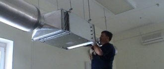
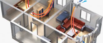
In houses with an area of more than 150 m2, it is more rational to equip an air duct system with mechanical drive. Where street air is prepared as much as possible before entering the room and distributed by fans to different rooms through a network of air ducts. An exception is that an individual supply must serve the kitchen, garage, bathroom, or bathroom.
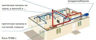
Rice. 4 - Mechanical ventilation of a private house
Calculation of natural ventilation of residential premises
The calculation consists of determining the supply air flow L during the cold and warm periods of the year. Knowing this value, you can select the cross-sectional area of the air ducts.
A house or apartment is considered as a single air volume where gas circulation occurs through open doors or a canvas cut 2 cm from the floor.
The influx occurs through unsealed windows, external fences and by ventilation, removal occurs through exhaust ventilation ducts.
Ventilation installation Source market.sakh.com
The volume is determined using three methods - multiplicity, sanitary standards and area. The largest is selected from the obtained values. Before calculating ventilation, the purpose and characteristics of all rooms are determined.
Basic formula for the first calculation:
L=nхV, m³/h, where
- V is the volume of the room (the product of height and area),
- n is the multiplicity determined according to SNiP 2.08.01-89 depending on the design temperature in the room in winter.
According to the second method, the volume is calculated based on the specific norm per person, regulated by SNiP 41-01-2003. The number of permanent residents, the presence of a gas stove and a bathroom are taken into account. According to Table M1, the flow rate is 60 m³/person per hour.
The third method is by area.
L=Axk, where
- A - room area, m²,
- k - standard consumption per m².
Calculation of the ventilation system: example
Three-room house with a total area of 80 m². The height of the premises is 2.7 m. Three people live.
- Living room 25 m²,
- bedroom 15 m²,
- bedroom 17 m²,
- bathroom - 1.4 m2,
- bath - 2.6 m²,
- kitchen 14 m² with four-burner stove,
- corridor 5 m².
It is necessary to calculate the air balance.
Separately find the flow rate for inlet and outlet so that the volume of incoming air is equal to the amount removed.
Inflow:
- living room L=25x3=75m³/h, multiplicity according to SNiP.
- bedrooms L=32x1=32 m³/h.
Total inflow flow:
L total=Lguest.+Lsleeping=75+32=107 m³/h.
Hood:
- bathroom L= 50 m³/hour (tab.SNiP 41-01-2003),
- bath L= 25 m³/hour.
- kitchen L=90 m³/hour.
The inflow corridor is not standardized.
By hood:
L=Lkitchen+Lbathroom+L baths=90+50+25=165 m³/h.
The supply flow is less than the exhaust. For further calculations, the largest value L=165 m³/h is accepted.
According to sanitary standards, calculations are carried out based on the number of residents. Specific consumption per person is 60 m³.
L total=60x3=180m/h.
Taking into account temporary visitors, for whom the established air flow is 20 m3/h, we can take L = 200 m³/h.
By area, the flow rate is determined taking into account the standard air exchange rate of 3 m²/hour per 1 m² of living space.
L=57x3=171 m³/h.
According to the calculation results, the consumption according to sanitary standards is 200 m³/h, the multiplicity is 165 m³/h, and the area is 171 m³/h. Although all options are correct, the first option will make the conditions more comfortable for residents.
Exhaust areas
Exhaust ducts remove exhaust air, excess moisture, and odors to the street. Outflow areas for natural ventilation of a private house are equipped in the kitchen, bathroom, bathroom, and, if necessary, in other rooms. Air intake grilles are placed at a height of 0 to 25 cm from the ceiling.
A separate shaft is allocated for the kitchen hood, which is not taken into account in the general calculations (it is turned on temporarily). If there is only one channel, then the equipment is connected through a tee with a check valve. The blades open when the hood is turned off, then the room is ventilated. The mine is considered working, but its increased resistance is taken away in the calculations.
Several channels can be combined into one only with the installation of a fan above all connections; without it, odors will flow between rooms. For the same reason, individual inflow/outflow is organized in technical rooms (basement, garage, furnace room). The doors are closed hermetically so that the flows do not mix with the home air exchange.
Bottom line
Knowing the air balance of a residential building, the size of the cross-section of the air ducts is selected. Most often, rectangular channels with an aspect ratio of 3:1 or round are used.
Home ventilation plan Source sustaintrust.org.nz
To conveniently calculate the cross-section, you can use an online calculator or a diagram that takes into account the speed and air flow.
For natural ventilation, the speed in the main and branch air ducts is assumed to be 1 m/h. In the forced system, 5 and 3 m/h, respectively.
With a required air exchange of 200 m3/h, it is sufficient to implement a natural ventilation system. For large volumes of transported air, mixed recirculation is used. Devices designed for performance are installed in the channels, which will provide the necessary microclimate parameters.
Ratings 0
Stages
The selection of the optimal air exchange system in terms of power and cost is carried out step by step. The design order is very important, since the efficiency of the final product depends on its observance:
- Determination of the type of ventilation system. The designer analyzes the source data. If you need to ventilate a small living space, then the choice falls on a supply and exhaust system with natural impulse. This will be enough when the air flow is small and there are no harmful impurities. If you need to calculate a large ventilation complex for a factory or public building, then preference is given to mechanical ventilation with the function of heating/cooling the inlet, and if necessary, then with calculations based on hazards.
- Outlier analysis. This includes: thermal energy from lighting fixtures and machines; fumes from machines; emissions (gases, chemicals, heavy metals).
- Calculation of air exchange. The task of ventilation systems is to remove excess heat, moisture, and impurities from the room with an equilibrium or slightly different supply of fresh air. To do this, the air exchange rate is determined, according to which the equipment is selected.
- Equipment selection. Produced according to the obtained parameters: required volume of air for supply/exhaust; indoor temperature and humidity; the presence of harmful emissions, ventilation units or ready-made multi-complexes are selected. The most important parameter is the volume of air required to maintain the design expansion ratio. Filters, heaters, recuperators, air conditioners and hydraulic pumps are used as additional network devices that ensure air quality.
Standard indicators
When designing an inflow and purification system, the purpose of the building, the technical premises of a separate apartment, office or bathroom are taken into account. In housing in the multi-apartment sector, the minimum volume of supplied air is 30 m3/person.
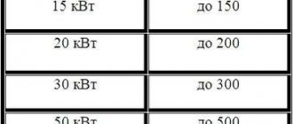
Table of air exchanges for premises GOST, SNiP
| Name | Multiplicity rate (m3/h) |
| Living common room (hall) | 3 |
| Kitchen in an apartment or hostel | 6 – 8 |
| Bathroom, shower | 7 — 9 |
| Toilet | 8 – 10 |
| Household laundry | 7 |
| Wardrobe and pantry | 1 – 1,5 |
| Garage, cellar | 4 – 8 |
| Cinema, theater, conference room | 20 – 40 m3 per person per hour |
| Office | 5 – 7 |
| Restaurant | 8 – 10 |
| Cafe, bar, billiard room | 9 – 11 |
| Supermarket, shopping area | 1,5 – 3 |
| Automotive repair shop | 6 – 8 |
| Gym | 80 m3 per athlete or 20 m3 per spectator |
| Public bathroom | 10 – 12 m3/h or 100 m3 per 1 toilet |
Selecting the height of the pipes
The next step is to determine the traction force that occurs inside the exhaust unit at a given height difference. The parameter is called available gravitational pressure and is expressed in Pascals (Pa). Calculation formula:
- p – gravitational pressure in the channel, Pa;
- H – height difference between the outlet of the ventilation grille and the cut of the ventilation duct above the roof, m;
- ρair – room air density, take 1.2 kg/m³ at home temperature +20 °C.
The calculation method is based on selecting the required height. First, decide how much you are willing to raise the exhaust pipes above the roof without damaging the appearance of the building, then substitute the height value into the formula.
Example. We take a height difference of 4 m and get the thrust pressure p = 9.81 x 4 (1.27 - 1.2) = 2.75 Pa.
Now comes the most difficult stage - the aerodynamic calculation of the outlet channels. The task is to find out the resistance of the air duct to the flow of gases and compare the result with the available pressure (2.75 Pa). If the pressure loss is greater, the pipe will have to be expanded or the bore diameter increased.
The aerodynamic resistance of the air duct is calculated by the formula:
- Δp – total pressure loss in the shaft;
- R – specific frictional resistance of the passing flow, Pa/m;
- H – channel height, m;
- ∑ξ – sum of local resistance coefficients;
- Pv – dynamic pressure, Pa.
Let us show with an example how the resistance value is calculated:
- We find the value of dynamic pressure using the formula Pv = 1.2 x 1² / 2 = 0.6 Pa.
- We find the friction resistance R from the table, focusing on the dynamic pressure of 0.6 Pa, flow velocity of 1 m/s and air duct diameter of 225 mm. R = 0.078 Pa/m (indicated by a green circle).
- The local resistances of the exhaust shaft are a louvered grille, a 90° upward outlet and an umbrella at the end of the pipe. The coefficients ξ of these parts are constant values, equal to 1.2, 0.4 and 1.3, respectively. Sum ξ = 1.2 + 0.4 + 1.3 = 2.9.
- Final calculation: Δp = 0.078 Pa/m x 4 m + 2.9 x 0.6 Pa = 2.05 Pa.
Let's compare the calculated pressure generated in the air duct and the resulting resistance. The traction force p = 2.75 Pa is greater than the pressure loss (resistance) Δp = 2.05 Pa, a 4-meter-high shaft is too high, it makes no sense to build one.
Now let’s shorten the ventilation duct to 3 m and recalculate again:
- Available pressure p = 9.81 x 3 (1.27 - 1.2) = 2.06 Pa.
- The resistivity R and local coefficients ξ remain the same.
- Δp = 0.078 Pa/m x 3 m + 2.9 x 0.6 Pa = 1.97 Pa.
The natural draft pressure of 2.06 Pa exceeds the system resistance Δp = 1.97 Pa, which means that a three-meter-high shaft will work properly for natural exhaust and will provide the required flow of removed gases.
Important note. The difference between the traction force and the resistance of the air duct was only 2.06 - 1.97 = 0.09 Pa. In order for the hood to work stably in any weather, it is better to take the height of the pipe in our example with a margin of 3.5 m.
The ventilation channel Ø225 mm can be divided into 2 smaller pipes, but not by diameter, but by cross-section. We get 2 round ventilation ducts 150-160 mm, as shown in the photo. The height of both shafts remains unchanged - 3.5 m.
How to simplify the task - tips
You could see that calculations and organization of air exchange in a building are quite complex issues. We tried to explain the methodology in the most accessible form, but the calculations still look cumbersome for the average user. Let's give some recommendations for a simplified solution to the problem:
- The first 3 stages will have to be completed in any case - find out the volume of emitted air, develop a flow pattern and calculate the diameters of the exhaust air ducts.
- Take the flow velocity to be no more than 1 m/s and use it to determine the channel cross-section. It is not necessary to master aerodynamics - calculate the diameters correctly and simply bring the air ducts to a height of at least 3 meters above the intake grilles.
- Inside the building, try to use plastic pipes - thanks to their smooth walls, they practically do not resist the movement of gases.
- Ventilation ducts laid in a cold attic must be insulated.
- Do not block the mine exits with fans, as is customary to do in apartment toilets. The impeller will not allow the natural hood to function normally.
To increase the flow, install adjustable wall valves in the rooms, get rid of all the cracks from where cold air can enter the house uncontrollably.